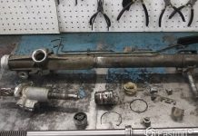
In detail: do-it-yourself repair of a Hyundai Solaris generator from a real master for the site my.housecope.com.
The generator is a rather complex and high-precision unit. For its disassembly, troubleshooting and assembly, special equipment is required. If you do not have the skills to perform such work, in the event of a generator failure, we recommend that you contact a specialized workshop for its repair or replace the complete generator.
You will need: keys "7", "10", "27", TORX T50 key, tester, puller, hammer, Phillips screwdriver.
1. Remove the generator from the car (see Removal and installation of the generator).
2. Keeping the generator shaft from turning, unscrew the pulley retaining nut.
3. Remove the pulley from the generator shaft.
The generator pulley is fixed against turning on the rotor shaft only due to frictional forces after tightening the nut of its fastening to the required torque. There are no dowels in the connection.
5. Mark in any way (for example, with a marker) the relative position of the stator and the generator covers to ensure the alignment of the holes for mounting the generator in the covers during reassembly.
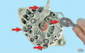
6. Remove the two screws securing the cover ...
8. Remove the three bolts securing the brush holder ...
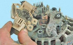
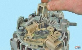
9. ... and remove the brush holder complete with voltage regulator.
10. Check the free protrusion of the brushes. If the size H is less than 5 mm, replace brushes or brush assembly. Check the ease of movement of the brushes in the brush holder.
If it wedges, the brush assembly must also be replaced.
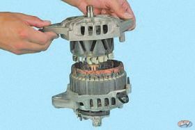
11. Remove the four tie bolts ...
12.… and remove the front cover.
13. Press the rotor out of the front bearing.
| Video (click to play). |
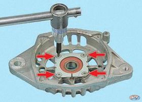
14. To replace the front rotor bearing, remove the four screws securing the pressure plate ...
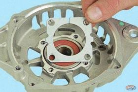
16. Press the bearing out of the cover.
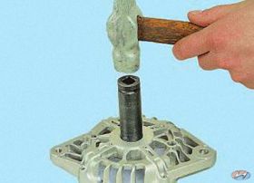
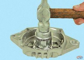
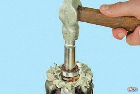
17. Press a new bearing into the cover using a mandrel of the appropriate diameter, applying force to the outer ring.
18. Check the ease of rotation of the bearing from the side of the slip rings. If, during the rotation of the bearing, play between the rings is felt, rolling or seizure of the rolling elements, damaged protective rings or grease drips, the bearing should be replaced. For this…
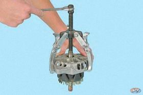
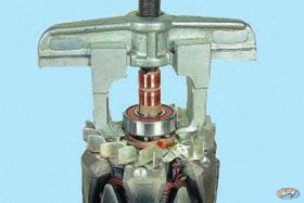
19.… press the bearing off the rotor shaft and fit a new one by applying force to the inner ring.
20. Press the new bearing onto the rotor shaft until it stops against the shaft shoulder, applying force to the inner ring of the bearing through a mandrel of a suitable diameter.
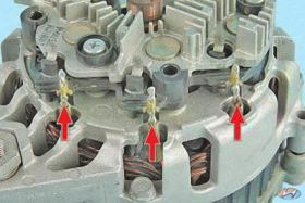
21. Open the contacts and disconnect the three stator winding leads from the rectifier unit.
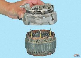
22. Remove the rectifier unit assembly with a cover.
The rectifier unit and the cover are a single unit and cannot be further disassembled, since the three diodes of the rectifier unit are pressed into the back cover and connected to the rectifier unit by welding.
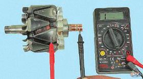
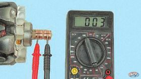
23. Check the absence of a short circuit between the rotor winding and the body by connecting the tester leads alternately to each slip ring and the rotor body. The tester should read infinity.
24. Check the resistance of the rotor winding with a tester by connecting it to the slip rings. If the readings on the tester show infinity, then there is an open circuit in the rotor winding and the rotor must be replaced.
25. Check the stator winding for open circuit, alternately measuring the resistance between all winding leads with a tester. If the measured resistance tends to infinity, then it is necessary to replace the stator.
26. Connect one test lead of the tester to the stator housing, and connect the other one at a time to each winding lead.The measured resistance should be very high (should tend to infinity). Otherwise, replace the stator.
27. Check the "positive" diodes by connecting the "negative" (black) tester probe to the "plus" terminal of the generator, and the "positive" (red) probe alternately connecting to the three contact terminals of the diodes. If the diodes are good, the tester will show 700-800 ohms.
28. Check the "negative" diodes by connecting the "negative" (black) tester probe to the "minus" terminal of the rectifier unit, and the "positive" (red) probe alternately connecting to the three contact terminals of the diodes. If the diodes are good, the tester will show an infinite resistance.
29. Connect the “positive” (red) probe of the tester to the “minus” terminal of the rectifier unit, and the “negative” (black) probe alternately connecting to the same three pins of the diodes. If the diodes are good, the tester will show 700-800 ohms.
30. If the tester shows low or close to zero resistance, the diode is "broken"; if the tester's reading tends to infinity regardless of the color of the connected probes, the diode is “open-circuit”.
In both cases, the rectifier unit must be replaced.
31. Assemble the generator in the reverse order of disassembly, orienting the generator covers and stator according to the previously made marks.
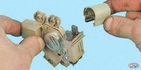
Before installing the brush holder, so as not to damage the brushes during installation, remove the cover of the brush unit ...
... install the complete brush holder with voltage regulator on the generator ...
... and refit the brush head cover.
We disassemble the generator to check and replace the voltage regulator with a brush holder and a rectifier unit.
Using the "8" head, unscrew two nuts ...
… And remove the generator casing.
With a high head "7" we unscrew two bolts and a special hairpin ...
... and remove the brush holder with voltage regulator assembly.
Using a Z-shaped wrench "24", unscrew the pulley fastening nut, holding the rotor shaft with a Torx T-50 wrench.
Using the "8" head, unscrew the four tie bolts.
Remove the back cover assembly with the stator and rectifier unit.
We take out the anchor from the front cover.
To replace the front bearing ...
…. Using the Torx T-20 wrench, unscrew the four screws securing the pressure plate.
Remove the bearing pressure plate.
We press out the bearing with a suitable piece of pipe or a tool head.
We press in a new bearing with a suitable piece of pipe or a tool head, applying force only to the outer ring of the bearing.
To replace the rear bearing ...
… We press the bearing off the rotor shaft with a puller.
We press on a new bearing with a suitable piece of pipe or a tool head, applying force only to the inner ring of the bearing.
We assemble the generator in reverse order.
Wherein…
... put the brush holder back in place ... ... and install the brush cover.
Symptoms: the battery discharge indicator does not go out after starting the engine, noise during generator operation, the generator does not provide the battery with sufficient charge.
Possible reason: the generator is faulty.
Tools and materials: cloth gloves, a set of heads and wrenches, a set of screwdrivers, pliers, a hammer, a marker, a vernier caliper, a tester.
Spare parts and fuels and lubricants:
front rotor bearing: 373342B400;
rectifier unit: 373602B100;
2. Unscrew and remove the alternator pulley retaining nut.
Note. While loosening the nut, prevent the shaft from turning by holding it with a wrench.
3. Separate the pulley from the generator by lifting it off the shaft.
4. Remove the spacer ring from the shaft.
5. Mark in any available way (for example, with a marker) the relative position of the stator and the generator covers.
Note. This is necessary to ensure the alignment of the generator mounting holes in the covers during its reassembly.
6.Unscrew and remove the two cover fixing screws.
7. Separate the shroud from the generator.
8. Unscrew and remove the three brush holder fixing screws.
9. Separate the brush holder with the voltage regulator from the alternator.
10. Check the brush holder.
- Check the protrusion of the brush holder brushes in a free state with a vernier caliper. The measured value (denoted by the letter "H in the attached photograph) should not be less than five millimeters.
- It is necessary to check the ease of movement of the brushes in the brush holder. There should be no: wedging, jamming and jamming of brushes.
Note. If a malfunction is found, replace the brush holder.
11. Unscrew and remove the four alternator front cover pinch bolts.
12. Separate the front cover from the generator.
13. Press out the alternator rotor from the front bearing.
14. To replace the front rotor bearing, unscrew and remove the four pressure plate retaining screws.
15. Remove the pressure plate.
16. Press out the front rotor bearing from the cover.
17. Press a new bearing into the cover using a diametrically suitable mandrel.
Note. Remember to apply force only to the outer ring.
18. Check if the bearing turns easily on the outer ring side. If during the rotation of the bearing you find play between the rings, rolls and seizures of the rolling elements, damage to the protective rings and lubricant drips, replace the bearing with a new one.
Note. To replace, follow the steps described in the next two paragraphs of this manual.
19. Press the bearing off the rotor shaft and then install the new bearing by applying force to the inner ring.
20. Press the new bearing onto the rotor shaft using a diametrically suitable mandrel until it stops against the shaft shoulder, applying force exclusively to the inner ring of the bearing.
21. Open the contacts, and then disconnect the three stator winding leads from the rectifier unit.
22. Dismantle the rectifier unit together with the cover.
Note. The rectifier unit and cover are non-separable units and, accordingly, their further disassembly is not provided. This is due to the fact that three diodes of the rectifier unit are pressed into the cover and connected to the rectifier unit using welding equipment.
23. Check the rotor.
- Check that there is no short circuit between the rotor winding and the housing. To do this, connect the tester probes in turn to each slip ring and rotor housing.
Note. In the absence of a short circuit, the tester should show a value tending to infinity.
- Check the resistance of the rotor winding with a tester in ohmmeter mode. To do this, connect its probes to the slip rings. The tester readings should not go to infinity,
Note. If a malfunction is found, the rotor must be replaced.
24. Check the stator.
- Check the stator winding for breakage, for which, in turn, measure the resistance between all winding leads using a tester. The tester readings should not go to infinity.
- Connect one tester probe to the stator housing, and connect the second one in turn to each winding lead. The value shown by the tester should tend to infinity.
Note. If a fault is found, the stator must be replaced.
25. Check the diodes.
- Check the positive diodes by connecting the negative (black) lead of the tester to the positive lead of the alternator, and the positive (red) probe alternately to the three contact leads of the diodes.If the diodes are working properly, the tester should show from 700 to 800 ohms.
- Check the negative diodes. To do this, connect the black (negative) test lead of the tester to the negative lead of the rectifier unit, and the red (positive) test lead alternately to the three contact leads of the diodes. If the diodes are working properly, the tester should show a value tending to infinity.
- Connect the positive (red) lead of the tester to the negative lead of the rectifier unit and the negative (black) lead to the same three diode leads. If the diodes are working properly, the tester should show a value from 700 to 800 Ohm.
Note. If a malfunction is found, the rectifier unit must be replaced.
26. Assemble the alternator in reverse order, orienting its covers according to the marks made during disassembly.
Note. When assembling the generator, consider the following: before installing the brush holder, in order to protect its brushes from damage, remove the cover of the brush assembly. Install the brush holder along with the voltage regulator into the alternator and then replace the assembly cover.
The Solaris generator can be repaired in case of minor breakdowns. Repair, as a rule, means the replacement of any elements of the generator - brushes, bearings, diode bridge. Generator whistling is also a common problem. Whistling, as a rule, appears due to problems with the belt tension (read the article "Replacing the alternator belt with a Hyundai Solaris").
We use a key for 12, 14, a head for 14.
- Remove battery negative connector.
- Use a wrench to grip the tensioner roller and turn it counterclockwise.
- Remove the poly V-belt from the pulley.
- Unfasten the retainer and remove the wires.
- Remove the cable holder.
- Open the protective cap of the generator terminal.
- Unfasten the nut, remove the power cable.
- Unscrew and remove the bottom bracket of the device.
- Do the same with the top bolt in the bracket.
- Remove the generator from the vehicle.
To replace the Solaris generator, it is enough to replace the removed device with a new generator assembly and put everything in the reverse order of removal. In case of repair work, it is necessary to disassemble the generator piece by piece.
After removing the generator, you can start repairing. We use a key for 7, 10, 27, TORX T 50, a multimeter, a hammer, a bearing puller, a set of screwdrivers.
- While holding the generator shaft so that it does not turn, remove the fasteners and remove the pulley.
- Remove the spacer ring.
- Mark the position of the stator in relation to the covers - this will allow you to correctly correlate the position of the covers in the future.
- Remove the cover (2 fasteners).
- Remove the brush holder together with the voltage regulator (3 bolts).
After removing the brush holder, the protrusion of the brushes should be evaluated. Provided that the value of H is less than 5 mm, it is necessary to replace the brushes separately or the entire assembly. Also, the elements change when the brushes get stuck. Read more about replacing the Solaris generator brushes in this article.
- Remove the front cover (4 bolts).
- Press the rotor out of the front bearing.
- Remove the pressure plate (4 screws).
- Press the bearing out of the cover.
- Press in the replacement with a mandrel of the correct size (the force is applied to the outer ring).
Next, we check the bearing near the slip rings. There should be no backlash during rotation, no drips of lubricant, the bearing should not wedge. If any of the above is observed, the bearing must be replaced.
- Press the bearing off the rotor shaft.
- Install a replacement by applying force to the inner ring.
- Press the element onto the rotor shaft until it rests against the shaft shoulder (the action is again directed along the mandrel to the inner ring).
- Press contacts.
- Detach the stator winding leads from the block 3.
- The rectifier unit is removed together with the cover (these parts are not further disassembled).
- After removal, it is imperative to test the winding for the presence of a short circuit in it - for this, connect the multimeter connectors to the slip rings (in turn) and to the rotor body. The optimal value is infinity.
- The winding resistance is also checked. But in this case, infinity speaks of a cliff. If found, the rotor should be replaced.
- Now the search for a break goes to the stator winding. To do this, it is necessary to measure the resistance between all the terminals of the winding in turn. An infinity value will indicate a malfunction of the stator.
- Also, the stator changes if the resistance value is not close to infinity when the probe is connected to the stator body and to all the terminals in turn.
- Connect the negative probe of the multimeter (black) to the positive terminal of the generator, and connect the positive probe (red) to the contact terminals of the diodes in turn (3 pcs.). This is how positive diodes are checked. Valid values are between 700 and 800 ohms.
- Now you need to swap the black and red probes - this is how the minus diodes are checked. The optimal value of the device is infinity.
- Now connect the red probe of the device to the negative terminal of the rectifier unit, and connect the black one in turn to the 3-pin terminals. The normal value is 700-800 ohms. A much lower resistance means that the diode is "broken", the opposite situation means that it is "open circuit". In both cases, the rectifier unit must be changed.
During the assembly process, it is important to pay attention to the installation of the brush holder. In order not to damage the brushes, you must first dismantle the unit cover, then put the assembled brush holder with a voltage regulator, then close the unit cover and fix it.
A car generator is a multicomponent and complex device that is quite difficult to repair yourself. To remove, disassemble and repair the Solaris generator, you must have the skill of working with a car in this manner. In the absence of the skill, it is better to contact the service or completely replace the failed generator.
The generator is a rather complex and high-precision unit. For its disassembly, troubleshooting and assembly, special equipment is required. If you do not have the skills to perform such work, in the event of a generator failure, we recommend that you contact a specialized workshop for its repair or replace the complete generator.
You will need: keys "7", "10", "27", TORX T50 key, tester, puller, hammer, Phillips screwdriver.
1. Remove the generator from the car (see Removal and installation of the generator).
2. Keeping the generator shaft from turning, unscrew the pulley retaining nut.
3. Remove the pulley from the generator shaft.
The generator pulley is fixed against turning on the rotor shaft only due to frictional forces after tightening the nut of its fastening to the required torque. There are no dowels in the connection.
5. Mark in any way (for example, with a marker) the relative position of the stator and the generator covers to ensure the alignment of the holes for mounting the generator in the covers during reassembly.
6. Remove the two screws securing the cover ...
8. Remove the three bolts securing the brush holder ...
9. ... and remove the brush holder complete with voltage regulator.
10. Check the free protrusion of the brushes. If the size H is less than 5 mm, replace brushes or brush assembly. Check the ease of movement of the brushes in the brush holder.
If it wedges, the brush assembly must also be replaced.
11. Remove the four tie bolts ...
12.… and remove the front cover.
13. Press the rotor out of the front bearing.
14. To replace the front rotor bearing, remove the four screws securing the pressure plate ...
16. Press the bearing out of the cover.
17.Press a new bearing into the cover with a mandrel of the appropriate diameter, applying force to the outer ring.
18. Check the ease of rotation of the bearing from the side of the slip rings. If, during the rotation of the bearing, play between the rings is felt, rolling or seizure of the rolling elements, damaged protective rings or grease drips, the bearing should be replaced. For this…
19.… press the bearing off the rotor shaft and fit a new one by applying force to the inner ring.
20. Press the new bearing onto the rotor shaft until it stops against the shaft shoulder, applying force to the inner ring of the bearing through a mandrel of a suitable diameter.
21. Open the contacts and disconnect the three stator winding leads from the rectifier unit.
22. Remove the rectifier unit assembly with a cover.
The rectifier unit and the cover are a single unit and cannot be further disassembled, since the three diodes of the rectifier unit are pressed into the back cover and connected to the rectifier unit by welding.
23. Check the absence of a short circuit between the rotor winding and the body by connecting the tester leads alternately to each slip ring and the rotor body. The tester should read infinity.
24. Check the resistance of the rotor winding with a tester by connecting it to the slip rings. If the readings on the tester show infinity, then there is an open circuit in the rotor winding and the rotor must be replaced.
25. Check the stator winding for open circuit, alternately measuring the resistance between all winding leads with a tester. If the measured resistance tends to infinity, then it is necessary to replace the stator.
26. Connect one test lead of the tester to the stator housing, and connect the other one at a time to each winding lead. The measured resistance should be very high (should tend to infinity). Otherwise, replace the stator.
27. Check the "positive" diodes by connecting the "negative" (black) tester probe to the "plus" terminal of the generator, and the "positive" (red) probe alternately connecting to the three contact terminals of the diodes. If the diodes are good, the tester will show 700-800 ohms.
28. Check the "negative" diodes by connecting the "negative" (black) tester probe to the "minus" terminal of the rectifier unit, and the "positive" (red) probe alternately connecting to the three contact terminals of the diodes. If the diodes are good, the tester will show an infinite resistance.
29. Connect the “positive” (red) probe of the tester to the “minus” terminal of the rectifier unit, and the “negative” (black) probe alternately connecting to the same three pins of the diodes. If the diodes are good, the tester will show 700-800 ohms.
30. If the tester shows low or close to zero resistance, the diode is "broken"; if the tester's reading tends to infinity regardless of the color of the connected probes, the diode is “open-circuit”.
In both cases, the rectifier unit must be replaced.
31. Assemble the generator in the reverse order of disassembly, orienting the generator covers and stator according to the previously made marks.
Before installing the brush holder, so as not to damage the brushes during installation, remove the cover of the brush unit ...
... install the complete brush holder with voltage regulator on the generator ...
... and refit the brush head cover.
The drive belt of the generator on the Hyundai Solaris is not for nothing that science is called the drive belt of auxiliary equipment. In addition to the generator itself, it drives several more units, therefore, its condition must be treated with special attention, as well as the tensioner.
Replacing the belt tensioner roller on the Hyundai Solaris is carried out without much difficulty , but without the necessary information, you can miss several important points that will affect the engine life as a whole.
Inspect the drive train every 30 km.
Inspection of the generator drive mechanism should be carried out at least every 30 thousand km .
At least that's what the manufacturer says. However, it should be understood that in the conditions of factory tests, not all the difficulties of the actual operation of the car are taken into account.
It is advisable to inspect the drive belt even more often, especially if the Solaris is with strong mileage. The belt tensioner pulley must be replaced or repaired if it starts to whistle, regardless of the number of revolutions of the crankshaft.
Whistling is most often recorded in damp and cold weather, but in especially advanced cases, it can always whistle.
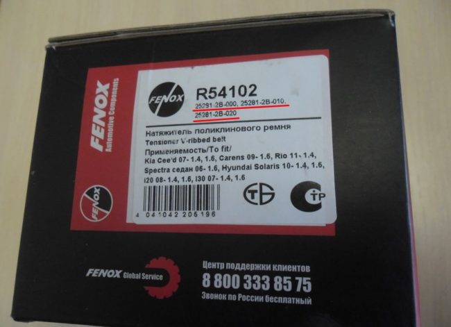
- The original tensioner pulley has a part number ST252812B010 , some manufacturers mark it T39210 or 25281-2B010 .
- The price of the drive belt tensioner roller at the officials floats within 7-8 thousand rubles .
- A similar video is installed on cars Kia Rio, Spectra, Soul and Cerate .
As practice shows, the roller should be changed along with the drive belt, so as not to return to this issue of 40-50 km at least.
Drive Belt Part Number - 25212-2B000 , and its price depends on the manufacturer (1200-2000 rubles).
Therefore, we start replacing the roller after the first noticeable whistling or at the first signs of wear on the drive belt. Nevertheless, the plant gives a guarantee for the video itself for five years or 150,000 km.
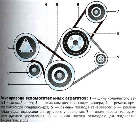
Accessory drive diagram.
Unlike engines of older models, there is no need to tighten the belt on Solaris. Both the 1.4-liter and 1.6-liter engines are equipped with an automatic poly V-belt tightening system. The belt itself sets in motion:
- Generator.
- Cooling system pump.
- Air conditioning compressor.
- Power steering pump.
The belt is driven by a crankshaft pulley, so any malfunction of the drive system can damage several units and systems at once.
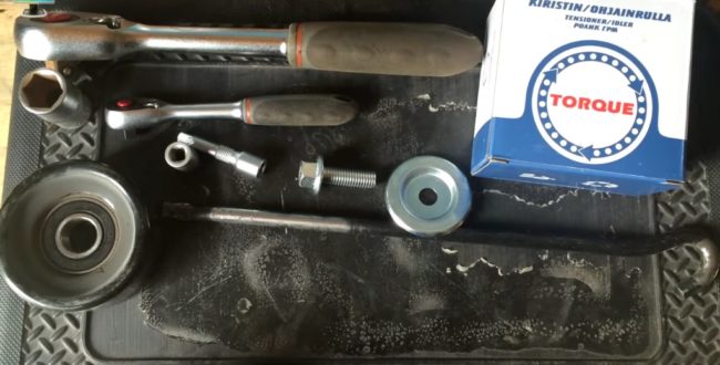
Replacement tools for idler pulley and alternator belt.
Replacing the generator belt tensioner roller is done by hand without any problems and using a minimum set of tools. The process is as follows:
- We set the car on a level surface, open the hood.
- Unscrew the upper generator mounting bolt.
Remove the upper alternator bolt.
It is necessary to loosen the lower bolt of the generator.
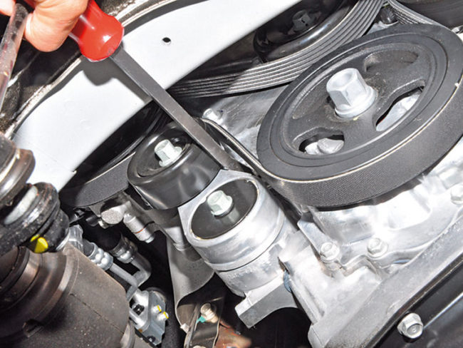
Use a spudger to pry the tensioner bracket.
Raise the machine with a hoist or jack on the right side.
Remove the right side guard.
Remove the alternator belt.
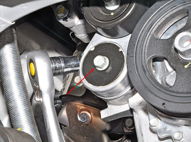
Remove the tensioner housing bolt.
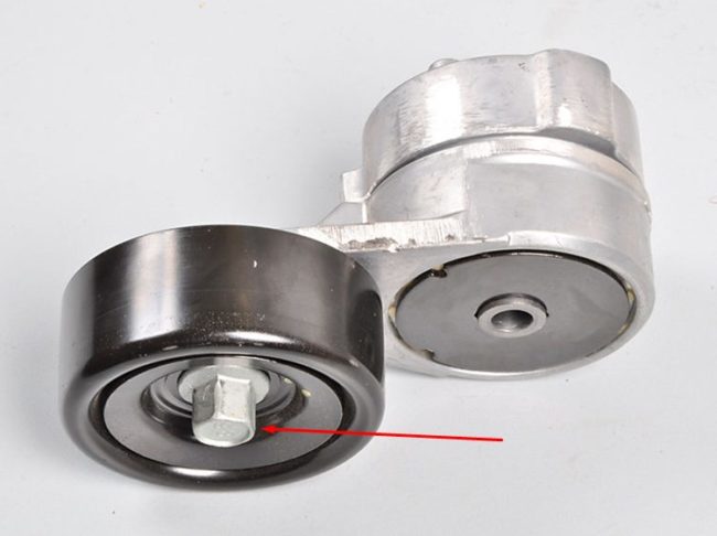
Remove the bolt securing the roller to the bracket.
When installing a new belt, it may be necessary to loosen the tensioning mechanism by sliding the roller towards the passenger compartment with a knob, as the new belt is tighter and is likely to be shorter than the old stretched belt.


