
In detail: do-it-yourself repair of a Mazda 626 generator from a real master for the site my.housecope.com.
Vitjuwo »19 Mar 2014, 13:43
Here is the same cap and the bolt below 14, that's all you need to unscrew at the bottom! A little higher is the connector, it must also be pulled out, it is done very easily and it is clearly visible!
Then we climb to the top.
and we see the gene from above, we take a nozzle or a key for 10 and unscrew it for a start, the tube that comes from the Power steering was unscrewed and set aside, it will be easier to work this way!
Next, we take a nozzle or a 12 key, and unscrew these 3 bolts, indicated by the arrows.
We twist it, so that there is a better move! it is necessary to successfully unfold it so that it can get through there!
Topic name must necessarily start with full name of the car model and convey to the user the main essence of the topic ... For example:
Mazda 6: how to replace the air filter?.
To create topics about buying / selling, a subforum is intended Mazda Buy / Sale !
Flood and offtopic are prohibited!
For creating themes for sale / purchase - immediately + 20%!
Group: MAZDAvod
Posts: 302
Registration: 04.07.2010
From: Volgograd
Said thanks: 42 times
Auto: Mazda626GC 2.0iGT 85 Mazda626GE 2.5l V6 96
Name: Vladimir
Post has been edited SANSKRIK - Aug 29 2012, 10:10
Petrol engine Removal On vehicles with a petrol engine with a working volume of 1.9 / 2.0 / 2.2 liters (90-136 HP), the generator is removed and installed from below, and on vehicles with a working volume of 2.5 liters (163 HP) - from above.
Warning. There is a risk of injury if the vehicle is lifted with a jack or special hoists.
• With the ignition off, disconnect the negative battery cable.
| Video (click to play). |
Attention. If the radio is equipped with a special. code (to prevent theft), it will be reset when the battery is disconnected. A distinctive feature of this type of radios is the word “CODE” or a red key icon on their control panel. The radio receiver can be put into operation only after entering the correct code, either at a specialized Mazda service center, or at the radio receiver manufacturing plant. In this regard, it is necessary to find out the specials in advance. the code.
• 90-136 HP: remove the front exhaust pipe.
• 163 hp: remove the air intake pipe.
Warning: do not open the coolant circulation system of the air conditioner. If refrigerant comes into contact with the skin, it may cause frostbite.
• Vehicles with a 2.5 l petrol engine: loosen the air conditioning compressor mounting bolts and, together with the pipes, place them against the cylinder block.
• Disconnect the wire from terminal -B- of the generator.
• Disconnect the multi-pin connector from the generator.
• Loosen the V-belt. To do this, on cars with a gasoline engine with a capacity of 90-136 hp. unscrew the generator clamping bolt and move the generator towards the engine. On vehicles with a 163 hp gasoline engine loosen the V-belt using the tensioning roller.
• Unscrew the fastening screws and remove the generator.
Installation • Place the alternator on the vehicle and secure with screws. On cars with a gasoline engine with a capacity of 90-136 hp. Do not fully tighten the screws.
• Put on and tighten the V-belt.
• Cars with a gasoline engine of 90-136 HP: fully tighten the alternator mounting screws and tighten the clamping bolt.
• Repair the multi-pin connector.
• Connect the connecting wire to terminal -B- of the generator.
• Vehicles with 163 hp petrol engine: fix the air conditioning compressor. Install the air intake and the underbody guard.
• Cars with gasoline engine 90-136 hp: install the front exhaust pipe.
• Connect the cable to the negative (-) battery terminal. If necessary, enter special. code into the radio and set the time on the clock.
• Lower the vehicle to the ground.
Gasoline engine with a displacement of 1.9 / 2.0 / 2.2 l 1 cross member 2 front exhaust pipe 3 bolt (120 Nm) 4 nut (45 Nm) 5 nut (25 Nm) 6 nut (25 Nm) 7 seal (replace with new one) 8 seal (replace with new one) 9 nut for connecting cable (25 Nm), terminal -B- 10 multi-pin plug connector 11 screw (45 Nm) 12 screw (15 Nm) 13 generator
Gasoline engine with a displacement of 2.5 liters 1 lower engine crankcase 2 screw (10 Nm) 3 screw (30 Nm) 4 A / C compressor 5 V-belt 6 screw (45 Nm) 7 screw (25 Nm) 8 screw (20 Nm) 9 connecting cable nut (25 Nm) , terminal -B10 Multi-pin plug 11 Generator 12 Nut (10 Nm) 13 Air inlet 14 V-belt tensioner
Diesel engine 55 kW / 75 HP
Removal To remove and install the generator, it is necessary to dismantle some parts of the front suspension and front wheel drive.
• Ignition OFF, disconnect the negative (-) battery lead.
Attention. If the radio is equipped with a special. code (to prevent theft), it will be reset when the battery is disconnected. A distinctive feature of this type of radios is the word “CODE” or a red key icon on their control panel. The radio receiver can be put into operation only after entering the correct code, either at a specialized Mazda service center, or at the radio receiver manufacturing plant. In this regard, it is necessary to find out the specials in advance. the code.
• Mark with paint the position of the right front wheel in relation to the hub. This will put the balanced wheel in the same position it was in before it was removed. Unscrew the wheel nuts, while the vehicle must be on the ground. Jack up the front of the vehicle and remove the right front wheel.
• Press the tie rod end - 1 - out of the steering knuckle.
• Press out the lower ball joint -7 from the steering knuckle.
• Unscrew nut -3- and press the anti-roll bar pivot rod out of the wishbone.
• Move right drive shaft -8- away from gearbox.
• Release tension and remove V-belt -9-.
• Disconnect electrical connector -10- from alternator.
• Remove the connecting cable from terminal -B- of the generator, to do this unscrew nut -11-.
• Unscrew bolt -12- with nut -13- and remove from bracket -14-.
• Unscrew screw -15- from bracket -16-.
• Remove alternator -17- from vehicle.
Installation • Install the generator to the vehicle.
• Secure bolt -12- with nut -13-.
• Fix alternator with bolt -15- to bracket -16-. The tightening torque of the bolt is 20 Nm.
• Tighten bolt -12- (40 Nm). Hold nut -13- against turning.
• Connect the connecting cable to terminal -B-. Tighten nut -11- (6 Nm).
• Connect the plug -10- to the alternator.
• Install and tension the V-belt.
• Install the right drive shaft.
• Install the anti-roll bar pivot rod into the wishbone.
• Mount the lower ball joint in the pivot arm.
• Install the tie rod end in the steering knuckle.
• Align the marks made when removing the wheel on the hub and front wheel. Lubricate the guides. Never lubricate the wheel nuts.
1 tie rod end 2 slotted nut (40 Nm) 3 nut (50 Nm) 4 articulated anti-roll bar 5 bolt 6 nut, install with washer (50 Nm) 7 lower ball joint 8 drive shaft 9 V-belt 10 multi-pin plug connector 11 nut (0 Nm) 12 bolt (40 Nm) 13 nut 14 generator bracket 15 screw (20 Nm) 16 screw 17 generator
Replace with new rusted wheel nuts. Tighten the wheel nuts. Lower the vehicle to the ground and tighten the nuts crosswise (110 Nm).
Connect the cable to the negative terminal of the battery. If necessary, enter special. code into the radio and set the time on the clock.
Diesel engine 74 kW / 100 hp With.
Removal • With the ignition off, disconnect the negative (-) battery lead.
Attention. If the radio is equipped with a special. code (to prevent theft), it will be reset when the battery is disconnected. A distinctive feature of this type of radios is the word “CODE” or a red key icon on their control panel. The radio receiver can be put into operation after entering the correct code, either at a specialized Mazda service center, or at the manufacturer of the radio receiver. In this regard, it is necessary to find out the specials in advance. the code.
Unscrew screw securing cable holder - 1 -.
• Unscrew nut -2- and remove the connecting cable from terminal -B- of the generator.
• Disconnect multi-pin connector -3-.
• Release tension and remove the V-belt.
• Unscrew screws -5- and remove bracket -6-.
• Unscrew bolt -7- while holding nut -8- against turning.
• Disconnect alternator -9- from bracket 10-.
Installation • Fix the generator to the bracket. Do not fully tighten the nuts.
• Fit the bracket and tighten the screws (25 Nm).
• Put on and tighten the V-belt.
• Tighten bolt -7- (45 Nm) while holding nut -8- against turning.
• Connect the multi-pin connector to the generator. Connect to terminal -B and fix the connecting cable with a nut (2 Nm).
• Fasten the cable to the bracket with screw -1-.
• Connect the cable to the negative (-) battery terminal. If necessary, enter special. code into the radio and set the time on the clock.
Cylinder head assembly
PERFORMANCE ORDER If the valves, cylinder head, levers guides and / or valve seats were replaced, the thickness of new compensation washers under the lever should be determined. For this job it is necessary.
Rear view mirrors
The interior mirror must be adjusted in height (hinge on the glass frame). Tilt the interior mirror to reduce glare when driving at night. Outside mirror position reg.
Brakes
A. Brakes squeak. Reason 1. Resonant noise between the disc and the rubbers. 2. Pads are worn out or hardened. 3. The brake surfaces of the discs are heavily dirty, oily or worn out. 4. Ref.
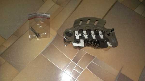
Lost charging from the generator. The charge lamp simply does not go out after starting the engine. Because the purchased relay-regulator has long been lying, it was decided to sort out the generator.
Removing the generator did not pose any particular problems, even in spite of the interfering gas system. I had to remove the pan of the air filter, after which the generator was pulled out.
I once had someone nailed a relay-regulator from Niva 2121. A cursory inspection showed that the wire from the external relay-regulator was 10 centimeters without insulation and was clearly shorting to ground.
Disassembling the generator was not particularly difficult. First, we clamp the pulley in a vise and unscrew the nut, I had it at 22, I used a wheel wrench.
We unscrew the tightening 3 or 4 bolts (along the perimeter of the generator), then knock down the front crusher with successive blows to the ears of the attachment (namely the front one, the one on the side of the unscrewed pulley).
Then you need to remove the rotor. To do this, turn the generator over with the pulley down and beat gently from below on the ear of the back cover, the rotor gradually comes out. Only then can you unscrew the bolts securing the diode bridge and the relay-regulator and remove the back cover of the generator.
Removing the back cover showed that the “revision” of the external regulator was very tough: they were using wire cutters. I had to order a new diode bridge.
Front and rear bearings were ordered together with the axle. there were still relatives on the generator.
I soldered the stator from the diode bridge with an 80 watt soldering iron, because 40 watt could not quickly warm up the place with solder, but heated the entire structure as a whole.
It is most convenient to assemble it back like this: first, install a diode bridge with a relay-regulator, then a stator, then, wielding round-nose pliers, we fill the stator contacts into the connectors of the diode bridge and the relay-regulator.After that, we solder it with the same 80 watt soldering iron. The main thing is to solder quickly, you do not need to heat the parts for a long time.
This was followed by the installation of a generator on the car.
The problem was that the external relay-regulator was hoisted in place in a barbaric way, cutting off the existing wires. In the diagram, three wires are suitable for the generator: plus (black), from the lamp from the dashboard (white-black), permanent plus (white-green, from a 30A fuse under the hood). Obviously found only black. Then I found a white and black, which turned out to be white and black with yellow rings.
But with white and green I had to tinker. Found a wire hanging in the air. I call it - 1.5 volts. Where could 1.5 volts come from !? At first I thought - the wire was rotten. Found a connector near the fuse box. From there came a black and red wire and a brown one with blue rings. He took off the connector, rang - 1.5 volts. Found a fuse, which, in theory, goes to the generator. It rings like a whole. I decided to check the fuse, which looks intact - it does not ring. Verdict - The fuse is dead. Replaced with a nearby one, the wire rang - 12 volts.
All wires go in one bundle with a black wire (plus for the battery).
After that, it was a matter of technology - to lengthen the bitten wires by soldering, insert them into the connector and try to start them. After starting the engine, the engine runs much more stable and better. Starts with half a turn.
Hi all.
the background is as follows.
the car was bought in a slightly zakolhozhen state, the charging was redone to an external relay Taz 2101.
step by step the car is put in order. much has been done, even more needs to be done :)
in general, it came to the generator .. ordered a charging relay. while the hands were going to charge from the car ran away. as they say pushing me to bulkhead genes 
the autopsy of the genes said that the Rayleigh would not work because the previous hosts installed the gene from GD / GV.
Well, now I turn to the essence of the topic.
the new gene on the existential is about 5 kiloru. seems to be not expensive, but damn the toad strangles
used in the region of 3 kiloru + probably a bulkhead with replacement of bearings, relyuhi .. which is also not particularly profitable ..
while he was deciding what to do, Koshak0082 suggested that he had a generator from a vaz 2110 installed on his car, without knowing it. all type of top worked. skinlu photo alterations.
as you understand, having weighed all the pros and cons, I did everything the same (although initially I was against such a rework) ..

in principle, in the photo you can see what and where I grinded.
additionally brought the power and control under the black cover to the side .. otherwise the contacts are a few mm from the oil filter ..
electrical connection:
power - in its place.
control: one of the 2 wires that went to the integral by checking with a lamp (on one the lamp burns brightly regardless of the ignition, on the second the lamp burns at full heat together with the control on the tidy when the ignition is on)
the alternator belt was custom-made in length of 905mm. (measuring which belt you will need with the most ordinary tape measure)
the upper mounting of the generator "narrowed" to the width of the tension of the native Mazda.
accordingly, the alteration consists of:
* in resharpening the native lower Mazda mounts (+ installing the upper bolt with a low hat so that the gene is pressed as close as possible to the block)
* fitting multiple genes details ..
results:
charging 14.3V without load, 14.1V near, far, stove .. there is no drawdown.
savings (for me less than 2 tr. for a new generator 2110 (90A) versus almost 5t.r. mazdo-generator (80A))
the ability to install 80A, 90A and even 110A.
control on the tidy works all the rules.
the belt is flat .. as expected.
and most importantly, spare parts for genes at every corner can be taken. (PS: this applies to Samara "SAP", "KZATE" and Bulgarian "Bulstart", "ELDIX" generators)
if someone needs to take pictures of the installed general on the car.
cons of this "upgrade":
fitting general is accompanied by obscenities towards the Japanese for installing genes under the inlet
you will have to work with a grinder, a hacksaw for metal, files
mazda 626 93USA, GE sedan, FS2, 5MKPP
VAZ 21083 97g.v. -> mazda 626 93 onwards GE hatch, FP, 5MKPP
vw new beetle -> mazda rx-8 HP
Last edited by region-74 on 23 Jan 2011 17:08, edited 1 time in total.
Problem: The starter motor stopped turning on the Mazda 626.
The light goes out, and the starter does not turn at all.
Using the “poke” method (or rather, lightly tapping the starter through the plank), it was found that the brushes had run out (after tapping, the starter turned, but not for long).
Method for replacing starter brushes for Mazda 626 No. 1
To replace the starter brushes in the Mazda 626, we need:
- a set of tools (screwdrivers, heads)
- cardan under the heads
- long collar
- powerful soldering iron, solder
- some gasoline
- grease
- observation pit
Immediately I will make a reservation that I did the first one consulted with the master by phone.
- Remove the battery. In principle, it is not necessary, but there will be more access, and it will not take long to remove.
- Remove the air filter with the body and all the giblets. It can be removed simply, all mounts are visible and well accessible. Thus, we get at least some access to the starter mount.
The figure below shows where the through bolts of the starter are located. In total, the starter is mounted on three bolts, two are accessible from the top and one from the bottom (if I am not mistaken, then the bolts are 13)
- We unscrew the two upper bolts using the cardan. We climb into the hole, remove the protection, unscrew the spacer between the cylinder block and the air manifold with a universal joint (it will interfere with pulling out the starter). Unscrew the third lower bolt. We take out the starter of their seat, unfold it more conveniently and remove the terminal and unscrew the nut and remove the second terminal. We take out and carry on the table.
- Starter disassembly is not difficult at all.
We unscrew two turnkey bolts from the back side (8k or 7k, in my opinion). We take out the long through bolts and remove the cover along with the brush block. We unscrew the contact of the brushes. We take out the rotor, watch the support ball, which is from the end of the rotor, do not lose it! With the rear cover removed, unscrew the 2 bolts for the slot, release the block with brushes. We look and are horrified how this could work at all!
By the way, you can see starters for UAZ at the link:
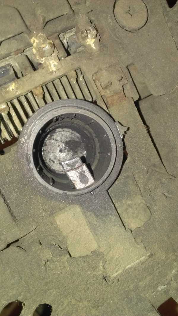
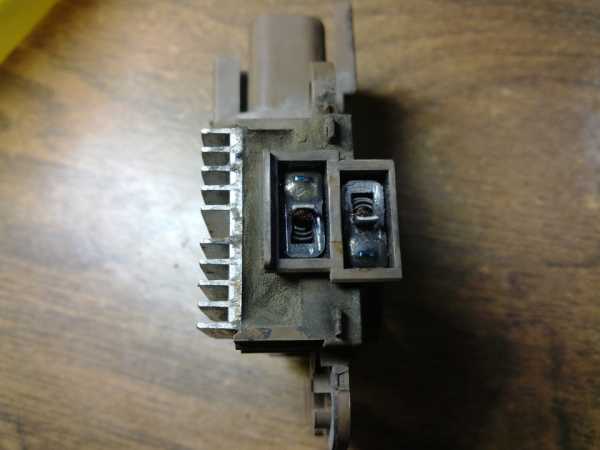
This is how the starter looks in a partially disassembled state:
But I found such a defect on my copy, perhaps this "hangnail" was the earlier death of the brushes. Contacts in carbon (I can imagine what kind of fireworks there was inside with such brushes.
We take out the brushes from the block. To do this, it is necessary to remove the springs and pull the brushes out of the seats.
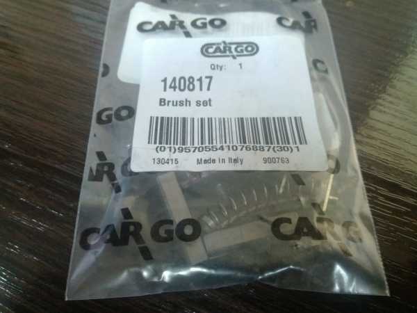
For replacement, Cargo brushes were purchased (it is written that Italy, under my starter).
Then we clean the rotor and the starter itself. Since it is full of graphite from worn brushes, everything needs to be cleaned. Then he rubbed it with a cloth soaked in gasoline.
We clean the rotor. I removed the bulge of the rolled contact with a file, then went over the contacts with a zero to remove carbon deposits. We clamp the rotor through wooden spacers into the teski, but not strongly, tear off the zero strip and wipe it along the radius of the contacts.
We get this is the result
-We collect the starter.
We solder the brushes.
I must say right away that there is nothing to do there with a simple household soldering iron! I used some old 42 volt one that looked like a hammer (in the truest sense of the word). The sting is very heavy and large. I waited for 20 minutes to warm up, but then he evaporated and soldered the brushes for me without any problems. After soldering the brushes, we do not start them on the seats.
We lubricate the bushings, put a support ball (it is on the side of the bendex, there is a seat for it) and put the rotor into the starter.
We put on a block with brushes. We put the brushes in the seats one by one. We expose the block under the mounting bolts with a slot. We put on the cover, We tighten the through bolts under the key. We center the block with an awl or something similar. We tighten the screws for the slot. We fasten the contact of the brushes.
We put on the motor in the reverse order of disassembly.
The brushes on the starter died, I immediately realized this, since I had already encountered a similar one!
Opening the hood, I freed up space to get to the two bolts, the first bolt unscrewed in three counts, but the second one licked it off, tried almost all the ways to unscrew it, went and bought a grinder and regretted it because this bolt is located in such a place that it is not crawl, I also bought various adapters, keys, heads, pliers, in short I spent a lot of time (about 12 hours), forces (- 1.5 kg.).
They advised me to take a chisel and a hammer, which I did. After a few blows, the bolt. Then he took a 13 wrench and crawled under the manifold with his left hand and unscrewed the nut that was tightened on the retractor, and also unscrewed the third bolt on the starter with the help of the head. He took out the starter from the generator side (it can be removed very easily). Dismantled the starter, changed the brushes, assembled it and put it back.
I want to draw your attention to the Starter Anchor, if it lacks a tooth, it will break the brushes, not grind them down, so they will not last for a long time (mine was enough for me for about 8 months) Photo below.
A client calls and tells about how the car was driving and stalled.
It stood, started up, and with grief in half, drove up to me on its own and completely died out in front of the gate. We have a planted battery and no charge. After a visual inspection, it seems like they found the reason. The power wire "+ B" from the generator has rotted away or burnt out.
I restored the wiring, charged the battery, start it up - there was no charging, and there is no charge. Further checks revealed that the generator was to blame. We remove, disassemble. We have melted insulation and up to a heap of turn-to-turn circuit in the rotor. After agreeing with the client, we come to a decision to replace the complete generator. We decided to stay at the factory restored, with a 2-year warranty. Issue price 6200 rubles. For comparison, a new one costs about 14,000 rubles.
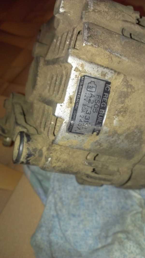
It should be said here that there were two types of generators on the 626 Mazda. Normal - with built-in relay regulator, with L-S control. These generators have been installed throughout the GE generation. And they differed in a simple control scheme.
The second type is ECU-controlled generators. The so-called generator with D-P control. In this case, a 1.5 V pulse signal comes to terminal D (drive) from the motor controller, which controls the field winding key. From the P (phase) terminal, a pulse signal of the excited state of the generator with a voltage of 9 V also goes to the controller. Accordingly, the “no charge” lamp in the dashboard is lit by the ECU. By changing the frequency of pulses on the D contact, the controller controls the voltage in the field winding, therefore, in the entire on-board network of the car. These generators have been installed on all 626s since 41997.
Now, knowing the device of the generator and the principle of its operation, it would be nice to analyze what we have. And we have a new generator that can repeat the consideration of its predecessor, if we do not establish the cause of the melted insulation. Logically speaking, this is nothing more than overheating of the rotor. I have to find out what caused it. And maybe the "+ B" terminal was not rotted away, but burned out? Overheating of the rotor can be caused either by a broken key in the generator's interior or by a constant signal from the controller, which in turn will open the key.
We put a new generator on the car. We connect the oscilloscope to pins P and D. We hang a voltmeter on the battery. We start the car. The charge control lamp goes out, the voltage on the battery is 14.3 V, the pulses come and go, but something is not right. I don't see it yet, but I hear it. The generator whines like wildly overloaded with consumers. Of the entire load, the fuel pump, control system and battery are turned on, everything else is turned off. A few seconds after starting, the frequency of the pulses on D increased sharply, approaching an almost open state. The generator has started to get very hot. We turn off the engine. It is necessary to measure what current comes out of the generator. I take a current clamp, the second channel of a 600A oscilloscope. We start the motor and I don’t believe my eyes, the current rises smoothly from 5A to …… 75A.In addition to the battery and the starter, I do not know other consumers capable of consuming such a current and not smoke. With all this, the voltage on the battery is 14-14.2 V. There are no complaints about the starter. The battery, according to the owner, was replaced 3 months ago and yet. We jam, remove the battery, temporarily put the first used one that came to hand. We start. The generator does not make noise, the recoil current rose to 15-17A and stopped there. Battery voltage 14.3 V.
We turn on all consumers (fan, heaters, all headlights and something else). The output current from the generator approached 65 A. The voltage dropped by 1 tenth. All OK.
Reason found. Internal short circuit in the battery. This, in turn, led to overheating and breakdown of the generator, as well as to melting and burning of the power wire attachment.
PS
A Chevrolet Tracker recently arrived with a similar defect in the battery.
Owner complaint: after the generator was repaired, after a few days the charging was lost again.
The generator was replaced and we came to check it. When measuring, the generator output current, idle with switched off consumers, was about 45 A.
It was recommended to immediately replace the battery.
After replacing the battery, the return current, under the same conditions, is about 23A.
I decided to try to replace the brushes on the generator (in the hope that the light will stop flickering) but at the same time the voltage regulator and the diode bridge! (As a result, the problem disappeared and there was a good charge!) I had some experience in parsing the generator! Therefore, without thinking twice, I climbed under the hood to remove the genk)) it is located under the intake manifold, photographed did not work! There is very little space, the Japanese fit everything compactly in the engine compartment)) I will briefly describe how I removed the generator! To begin with, I threw off the negative terminals from the battery and turned off the wire chip that fits the generator! Then, unscrewed with a key 13 wires leaving the generator (carrying a charge to the fuse box and to the battery). The next step was to loosen and remove the belt! The bolt was loosened with a key of 12 (if memory serves)) then we unscrew the bolt securing the generator to the cylinder block! The key came up at 14! The whole thing is not difficult, but because of the tightness I had to chirp for a long time! I advise you to use a ratchet wrench - it will go much faster))
The hardest part ahead is pulling out the generator! Maybe someone filmed from the bottom, but we don't go easy ways and decided to pull it out through the top! For ease of pulling through, unscrew the bolt securing the hose coming from the gur through the valve cover (on top of the engine)! Well, then twist, twist, look for the position in which the generator will come up))
So, after 15-20 minutes of torment, we still pulled out the generator! Now let's clean it from dirt with an iron brush and start disassembling it!
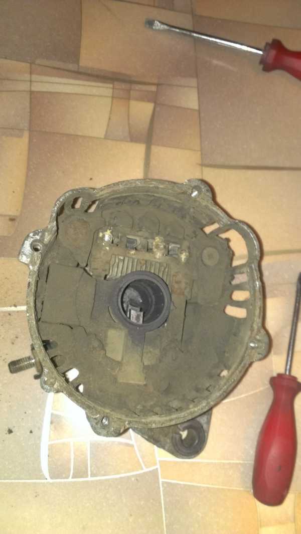
In order to disassemble the generator, we need a Phillips screwdriver and a 10 wrench! We turn off the key to which the wires are attached (leading to the battery), then with a screwdriver we unscrew the 4 bolts securing the generator covers. Further, as you like and conveniently! Take a hammer or a flat, thick screwdriver and quietly, around the entire circumference of the generator, begin to squeeze the top cover!
Squeeze gently so that the generator winding remains in the cover with brushes and a diode bridge (although if you are going to change everything, you can barbarously rip it out, but not the fact that the winding will not suffer!) The next step is to do this: heat the soldering iron and unsolder from 4 contacts of the diode bridge 4 wires winding! Having unsoldered the wires, you need to just as carefully, without damaging the winding, pull this winding out of the generator cover with a screwdriver or other improvised means))) We take a screwdriver, turn off the brushes with a voltage regulator (as it turned out later, during the opening, this is one part) and a diode the bridge is just three bolts!
After all these operations, you can clean and wipe everything! I think you have a lot of dirt, like I have accumulated there over 20 years)))
Putting it all in reverse order! When you screw on the new brushes with the regulator and the diode bridge, carefully put the winding in place.Make sure that the wires fit clearly into their seats! This will make it easier for you to solder them in the future))) As a result, you must solder 4 wires and 2 contacts of the regulator with brushes to the diode bridge! Further, a small nuance: do not forget to insert the wire through the hole in the lid and fix the brushes - this will facilitate further collection of the generator and will not damage the brushes! After assembling the generator, do not forget to pull out this wire))
Well, then, as we disassembled and assemble it!
If you have any questions, write! I will help how I can)))
The charge disappeared, the generator began to warm up. - logbook Mazda 626 My Japanese tractor in 1985 on DRIVE2
The specified didod calls both directions, he checked the truth with an ordinary Chinese tester.
Hello everyone, I need your help! Today the generator has started to stand out or there is a problem with the wiring. Actually, I would like to consult with you on this issue. I have a voltmeter in my cabin, but today it suddenly started signaling that the voltage had dropped below 12V. I immediately thought that the generator had died, but if we turn on the gas and turn off the consumers, the voltage rises to 12.7. Usually, the voltage below 13.5 does not drop even with a stove and headlights. The generator gets very hot, you can't hold your hand. Another such moment, when you turn the key in the ignition, before all the lights on the tidy came on (those that go out after the start), now they do not light up. The other day I changed the alternator belts, I have two of them. I ordered 2 pieces of new ones, but they seem to have arrived a little different in length, I think that the factory is defective, since they should be the same. Actually, when I changed the belts, I found that there was a slight play in the pulley. I have several assumptions that this could be: 1. bearings under the load of belts spin badly and therefore the gene itself heats up, can this also affect the voltage (or cannot)? 2. something is short in the gene? (winding for example), because it heats up. 3. Something somewhere is whiling away in the car, the battery is vryatli (banks in the sense), since now it is charging at home, it takes the charge normally.
Where to look, what to expect. how to overcome this case. I will be glad to your advice. Thank you.
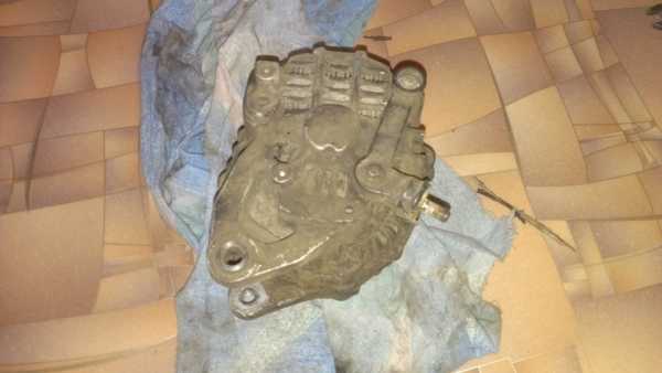
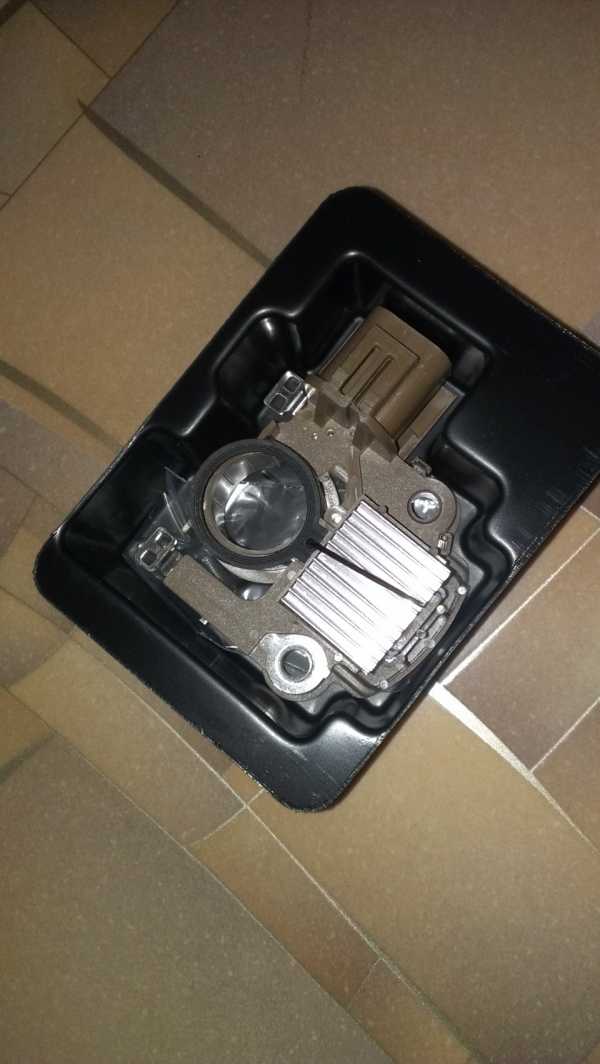
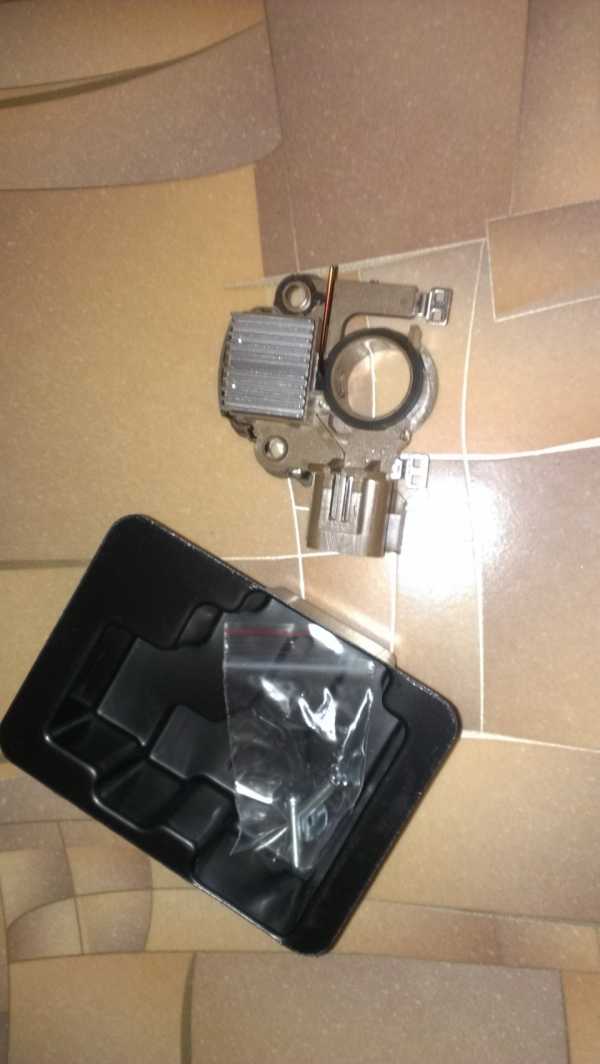
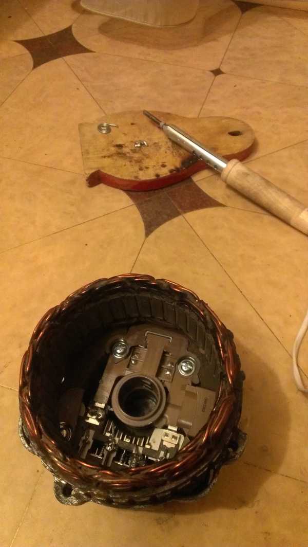
So the moment came when my battery light came on. It happened very unexpectedly. He drowned the car, went on business, returned after 5 minutes. I'm looking for some, I immediately hear a strange hum and the battery light comes on. And immediately to myself I think about how to remove the generator, I read a lot that it is difficult to get it. I drove into the garage and got to work. I'll tell you if there are no air conditioner pipes, then the generator is very easily removed from the top. It is necessary to remove the oil dipstick, unscrew the hydraulic booster tubes, unscrew and set aside the entire vacuum system, unscrew the generator mount and then the generator can be safely removed from the top. It took me about 30 minutes slowly.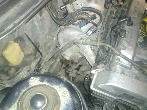
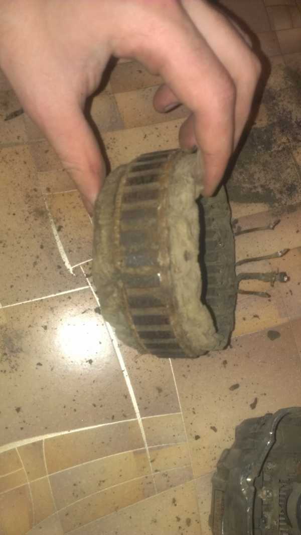
This is how the generator is taken out
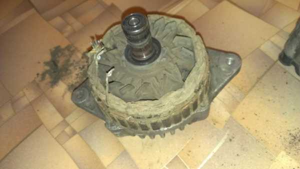
All that is left of the brushes
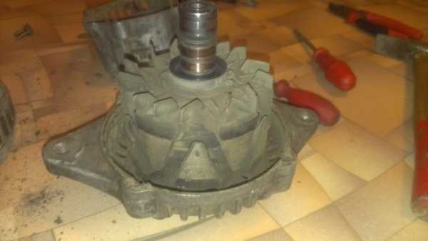
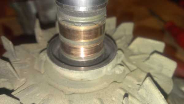
Old front bearing
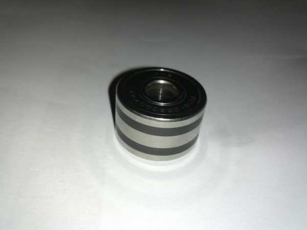
It feels like the generator was not serviced from the factory. The repair cost $ 50. Front bearing FAG 6303RSR - $ 7 Rear bearing Cargo 140419 - $ 6.5 Transpo IM830 generator relay - $ 14
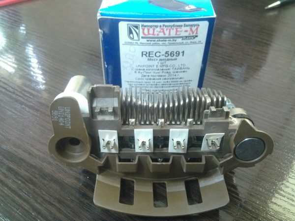
Diode bridge Unipoint REC-5691 - $ 18
But there was one of my jamb, when I disassembled the generator, I noticed that the brushes were worn out, and therefore I decided that it was because of the bottom. I changed the brushes, put the generator on, start looking for some, and everything remains the same - the lamp is on and there is some kind of unbearable hum. I had to remove the gene again, order a relay and a diode bridge, change everything and put it in place. Now fully serviced the generator - one less problem.
DIY generator repair. Dismantling the Mazda generator


