In detail: do-it-yourself repair of the Moskvich 2140 generator from a real master for the site my.housecope.com.
The Moskvich 2140 car is equipped with a 29. 3701 generator. The 29.3701 generator is a three-phase twelve-pole synchronous electric machine with a built-in small-sized integral voltage regulator Ya112A... The generator is equipped rectifier block BPV4-60;
1. Possible generator malfunctions
2. Scheme of connecting the generator to the car network
3. Diagram of the AZLK 2140 generator
4. Dismantling the generator
5. Technical inspection of the generator on the Moskvich 2140
6. Links to our forum - ask questions
1. Possible malfunctions of the Moskvich 2140 generator
2. Scheme of connecting the generator to the electrical circuit of Moskvich 2140
1 - rechargeable battery
3. Diagram of the generator on Moskvich (AZLK) 2140
Description of generator parts on Moskvich 2140
9 - bolt of fastening of the integral voltage regulator;
10 - integral voltage regulator;
4. Dismantling the generator of the car Moskvich 2140
Algorithm for disassembling the Moskvich 2140 generator:
1. Unscrew the two screws securing the integrated voltage regulator and remove it.
2. Unscrew the two screws in the brush holder and detach the brush holder from the integral device.
3. Unscrew the nut securing the connector block of the "O" output of the generator (output to the charge indicator lamp), disconnect the block from the wire end and remove it.
4. Unscrew the tie rods.
5. Remove the cover from the slip ring side together with the stator.
6. Disconnect the stator phase windings from the terminals on the rectifier unit in the cover on the side of the slip rings.
7. Unscrew the pulley retaining nut and remove the pulley.
8. Remove the fan, spacer sleeve and remove the key.
9. Remove the drive end front cover from the rotor shaft.
10. Remove the four bearing retainer screws and press the bearing out of the drive end cover seat.
| Video (click to play). |
5. Technical inspection (TO) of the generator on the Moskvich 2140
The sequence of technical inspection (TO) of the generator on a Moskvich 2140 car:
1. Inspect the stator winding and check the resistance of the windings with a tester or ohmmeter. The resistance should be approximately the same (the difference is no more than 10%).
2. Check the resistance of the rotor coil. The resistance between the slip rings should be 3.7 ± 0.2 ohms.
3. Check the height of the brushes, which should be at least 8 mm.
4. Check bearings and replace if necessary.
5. Inspect the slip rings. Wear should not exceed 0.5 mm in diameter. If the wear is greater than the ring you need to grind. The minimum permissible ring size is 28.5 mm.
6. Check that the rectifier unit is in good condition. Check only the disassembled generator and the disconnected stator winding. Check the diodes with a tester by changing the polarity.
In one case, a working diode will not conduct current, in the other it will conduct with resistance. A broken diode will conduct current at any polarity.
6. Links to our forum - ask questions
charging suddenly began to disappear.
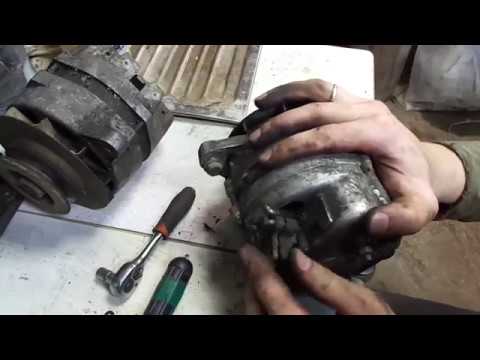
we climb into the generator.
in the absence of an electrical circuit, we remember the initial connection
and here is the reason for the lack of charging - a stuck brush
unscrew the bolt tightening the stator halves, using a puller, remove the cover with the bearing from the rotor
unscrew the bearing race from the inside
mercilessly knocking out a worn out bearing
remove the rear bearing cover by prying it off with a screwdriver. she is just seamed
slip rings were ideal))
assemble in reverse order with new bearings
Slip rings are not quite ideal, but they will still work to their fullest. But the main mistake is that the bearings were not opened before installation and grease was not put there.
the paths of the rings are practically without a step, the finger is not even particularly felt, i.e. minimal wear.
what is rubbed by the tracks is even better, the larger the contact patch - the more bandwidth))
and bearing manufacturers now och save on grease? I had hoped for them.
Generator technical characteristics:
Rated voltage, V. 14
Maximum current strength, A. 50
The rotor speed at which a voltage of 12.5 V is reached at a temperature of 20 & # 177 5 & # 176 C of the generator, rpm:
& # 160 & # 160 at a current of 0 A. 1100
& # 160 & # 160 at a current of 32 A. 2000
Adjustable voltage, V. 13.5-14.8
Capacitor capacity, μF. 2.2
The size of the brushes, mm. 6.5x6x13
Pressing force of brushes, N 2.5 & # 177 0.5
Gear ratio from crankshaft to generator. 1.69
The engine is installed generator 292.3701 with built-in small-sized integral voltage regulator Ya112A. The generator is a three-phase 12-pole synchronous electric machine equipped with a rectifier unit consisting of six diodes connected in a three-phase bridge rectifier circuit. The Y112A voltage regulator is mounted on the brush holder body and closed with a metal body. The voltage regulator cannot be repaired.
The generator and voltage regulator are checked when signs of possible malfunctions appear.
It is impossible to test the generator for sparking.
Do not check the generator with a voltage of more than 12V or a megohmmeter.
If there is no device for measuring the voltage produced by the generator, you can increase the engine speed to 1500 rpm and disconnect the battery. If the engine stalls, the alternator is not charging.
Generator 292.3701-01 and its electrical diagram:
1 and 16 - covers; 2 - rectifier unit; 3 and 17 - bearings; 4 - bearing cover; 5 - slip rings; 6 - a sealing ring; 7 - brush; 8 - brush holder; 9 - bolt of fastening of the integral voltage regulator; 10 - integral voltage regulator; 11 - regulator casing; 12 - pole piece; 13 - excitation winding; 14 - stator plates; 15 - steel sleeve; 18 - key; 19 - grower; 20 - pulley nut; 21 - pulley; 22 - distance sleeve; 23 - fan; 24 - stator winding; 25 - tie rod; 26 - output of the “Ш” terminal; 27 - output of the terminal "O"; 28 - terminal output “+”; 29 - capacitor.
Dismantling the generator.
1. Unscrew the two screws securing the integrated voltage regulator and remove it.
2. Unscrew the two screws in the brush holder and detach the brush holder from the integral device.
3. Unscrew the nut securing the connector block of the "O" output of the generator (output to the charge indicator lamp), disconnect the block from the wire end and remove it.
4. Unscrew the tie rods.
5. Remove the cover from the slip ring side together with the stator.
6. Disconnect the stator phase windings from the terminals on the rectifier unit in the cover on the side of the slip rings.
7. Unscrew the pulley retaining nut and remove the pulley.
8. Remove the fan, spacer sleeve and remove the key.
9. Remove the drive end front cover from the rotor shaft.
10. Remove the four bearing retainer screws and press the bearing out of the drive end cover seat.
Inspection, check and elimination of malfunctions of the generator.
After disassembling the generator:
1. Inspect the stator winding and check the resistance of the windings with a tester or ohmmeter. The resistance should be approximately the same (the difference is no more than 10%).
2. Check the resistance of the rotor coil. The resistance between the slip rings should be 3.7 & # 177 0.2 ohms.
3. Check the height of the brushes, which should be at least 8 mm.
4.Check bearings and replace if necessary.
5. Inspect the slip rings. Wear should not exceed 0.5 mm in diameter. If the wear is greater than the ring you need to grind. The minimum permissible ring size is 28.5 mm.
6. Check that the rectifier unit is in good condition. Check only the disassembled generator and the disconnected stator winding. Check the diodes with a tester by changing the polarity. In one case, a working diode will not conduct current, in the other it will conduct with resistance. A broken diode will conduct current at any polarity.
After inspecting, checking and eliminating defects, assemble the generator in the reverse order to disassembly.
The rotor speed at which a voltage of 12.5 V is reached at an ambient and generator temperature of 20 + 5 ° C in an unheated state of the generator with independent excitation is 12.5 V, rpm, no more:
- at load current equal to 0
- at a load current equal to 32 A
The regulated voltage at a generator rotor speed of 3500 rpm and a load current of 16 A with a connected battery at an ambient temperature of 20 + 5 ° C should be, V
Rice. 211. Generator 292.3701: 1 - cover from the side of slip rings; 2 - rectifier unit; 3 - screw for fastening the bearing cover; 4 - ball bearing; 5 - ball bearing cover; 6 - slip rings; 7 - ring; 8 - brush holder; 9 - screw for fastening the brush holder and voltage regulator; 10 - voltage regulator; 11 - casing of the voltage regulator; 12 - poles; 13 - excitation winding; 14 - stator; 15 - bushing; 16 - cover from the drive side; 17 - ball bearing; 18 - pulley key; 19 - washer; 20 - nut for fastening the pulley and fan; 21 - pulley; 22 - fan; 23 - distance sleeve; 24 - stator winding; 25 - tie rod; 26 - output of the “Ш” terminal; 27 - output "O" (only for 292.3701); 28 - conclusion "+"
The engine is equipped with a 292.3701 generator (Fig. 211) with a built-in small-sized integral voltage regulator Ya112A. The generator is a three-phase twelve-pole synchronous electric machine equipped with a BPV4-60 rectifier unit, consisting of six silicon diodes connected to a three-phase bridge rectifier circuit. The Y112A voltage regulator is mounted on the plastic housing of the brush holder and covered with a metal casing. The Y112A voltage regulator cannot be repaired.
The electrical diagram of the generator is shown in Fig. 212.
Rice. 212. Electric circuit of the generator 292.3701: 1 - stator winding; 2 - excitation winding; 3 - voltage regulator; 4 - rectifier unit
Possible generator malfunctions and methods for their elimination are given in table. 33.
Table 33. POSSIBLE GENERATOR FAILURES AND METHODS OF THEIR ELIMINATION
The device and operation of the car Moskvich-412
Our additional services and sites:
A faulty generator stops supplying energy to the vehicle's electrical network.
Before checking the operation of the generator, you must make sure that the wire lugs are securely connected to the terminals of the generator, the relay-regulator, the starter and the output Pins of the battery, as well as the proper tension of the fan belt.
Most often, the generator stops working due to contamination of slip rings, brushes and brush holder. Because of this, reliable contact between the brushes and slip rings is broken, increased sparking begins, which leads to burning of the rings and brushes, as a result of which the generator stops working. In this case, remove the complete brush holder with brushes and clean the slip rings, brushes and brush holder as described in chap. 10.
If, after cleaning and checking the slip rings and brushes, the generator still does not work, it is necessary to check the condition of the diodes of its rectifier. To do this, you should:
unscrew the screws 20 (see Fig. 57) and remove the brush holder 15 complete with brushes;
unscrew the tightening screws 8 and, using a puller, remove the back cover 10 of the generator together with the stator 21;
Disconnect the ends of the stator winding from the bolts in the rear cover. The diodes are checked with a current from a storage battery or other direct current source with a voltage of 12 V. The poles of the battery are connected to the terminals of the diode through a test lamp (you can use a portable car lamp). First, a wire from the plus of the battery is connected to one of the terminals of the diode through the lamp, and a wire from the minus of the battery is connected to the second terminal, then the wires are swapped. A working diode passes current (the lamp is on) only in one direction, indicated by an arrow on the diode body. Burning the lamp when voltage is applied in both directions indicates the presence of a breakdown in the diode, but if the lamp does not light for any connection of the ends, then there is an open circuit in the diode. In both cases, the diode must be replaced. To do this, you need to unsolder the wires connected to the diode, unscrew the nut of its fastening to the radiator or generator cover, install and fix a new diode of the same polarity (replacing D242A diodes with D242AP diodes and vice versa is unacceptable). The wires should be soldered to the diode at a temperature not exceeding 150 ° С and not longer than 5 s.
If, after checking the condition, cleaning the brushes and slip rings and replacing the faulty diodes, the generator does not recover, it is necessary to check the condition of the stator and rotor windings.
This check should be carried out by a qualified electrician using the instruments.
In case of damage to the generator windings, the stator or rotor should be replaced, respectively, by completely disassembling the generator.
A feature of the Moskvich 2140 cars is the modernization that took place in 1981. When carrying out routine maintenance, this fact must be taken into account, since the changes have affected many nodes, including the electrical equipment of the car.
Factory wiring diagram Moskvich 2140, produced until June 1981
The Moskvich 2140 is the result of a deep modernization of the "412" model.
By the mid-eighties, the old model stopped responding to global demands, especially:
- Outdated body shape, which did not allow to equip the car with passive safety systems;
- The slightly functional interior was inferior to domestic counterparts, not to mention the imported car models with which it competed;
- Informative instrument panel. In addition, it was also traumatic, since no one worked in those years on safety issues in road accidents;
- Ineffective braking system, etc.
The model that served as a platform for the creation of the Moskvich 2140
The modernized "one hundred and fortieth" first rolled off the factory assembly line in 1976.
In accordance with the factory classification and applicable industry regulations, the restyled sedan model received the name:
- "Moskvich-2140". The model was equipped with an UZAM-412 engine;
- "Moskvich-2138". The model was equipped with an M-408 engine.
For reference: The predecessor "412" appeared in the AZLK line due to the development of a new UZAM-412 engine. Its resource and technical capabilities turned out to be promising and modern, which made it possible to complete all subsequent models with this power unit.
The three millionth copy of Moskvich 2140 was deposited in the factory museum
Starting in 1981, the Moskvich 2140 was no longer equipped with the M-408 engine due to its low power (56 hp), which did not meet modern requirements. And the model itself was restyled.
Among the most radical differences between the "one hundred and fortieth" from its predecessor can be noted:
- Front disc brakes (earlier drum brakes were installed on the front and rear axles);
- The vents disappeared from the front doors;
- The car received a new bumper design;
- All chrome moldings have been removed from the exterior, including the chrome grille;
- The interior now has armrests and seats with headrests.
For reference: the updated model received the index 2140-01. The advertising video of those years in every possible way emphasized the changes made to the design of the car. Also for the first time on cars on the radiator grill appeared the inscription "AZLK".
Photo of the color scheme of the modified "one hundred and fortieth"
The export version had the factory index M-2140-117, and in everyday life the car was named "Moskvich-1500 SL".
Of the features, it should be noted:
- "Low" dashboard with new instruments and controls;
- Modern interior trim;
- New tail lights (all produced by Yugoslav companies).
Poster advertising the export Moskvich-1500 SL
For reference: it should be noted that the Moskvich 2140 car for the first time in domestic practice was painted with modern paintwork materials - "metallic". And although the price of cars increased slightly, the car was unable to provide past sales.
At the beginning of the 90s, the electrical circuits of the Moskvich 2140 were also seriously modernized. In particular:
- In a double-circuit brake system with a vacuum booster, an electrical circuit of a sensor with a warning lamp for a low level of brake fluid in the expansion tank has appeared;
- A modern control system of the new instrument panel was installed on the car;
- A dual-mode alarm has been added as standard.
Color wiring diagram Moskvich 2140, produced since June 1981
For reference: The alarm system functioned in two modes - day and night. According to the developers, bright light is needed only during daylight hours, while direction indicators and brake lights at night can blind drivers behind driving cars.
This function was implemented as follows:
- When the alarm button was activated, the incandescent lamps in the brake lights and side lights worked as standard;
- In the dark, when the outdoor lighting (dimensions and dipped headlights) was turned on, an automatic switch to the "night" mode of operation took place - the lamps were burning at full speed.
The factory manual describes in detail the operation of light and sound alarms.
Tip: When servicing a car with your own hands, you should take this feature into account and do not try to change the wiring diagram.
The contact ignition system, traditionally used in Soviet cars, was responsible for the operation of the power unit:
- When the engine was started, the battery (in the diagram # 10) fed the ignition coil (# 9);
- It generated a high voltage current and applied it to the ignition distributor (# 8);
- The distributor transmitted discharges to the spark plugs (No. 7), which ignited the air-fuel mixture in the cylinders.
Classic contact ignition system of the car Moskvich 2140
After starting the engine, the key is in the ignition lock (no. 1):
- Returned to the all-inclusive position;
- I disconnected the battery from the circuit - instead, the generator (No. 4) supplied the current to the ignition coil;
- The battery was recharged from the generator through the charge relay (No. 2).
For reference: Maintenance of the ignition system was limited to checking the gap between the electrodes of the spark plugs and cleaning the contacts in the distributor cover, which could burn.

