In detail: do-it-yourself repair of the opel astra g generator from a real master for the site my.housecope.com.
- Thank you
- No thanks
- Thank you
- No thanks


- Thank you
- No thanks


- Thank you
- No thanks


- Thank you
- No thanks


No, no nada, specialists are the same people, not celestials, if there is a desire, and most importantly, enough free time to figure it out, to pick up the bearings you need - it's better to do it yourself. Better than for himself - no specialist will do it, because for him it is a routine, but for you it is your dear detail.
I personally do not remember now what and how, but a few years ago I dismantled the current to a friend a Boshevsky generator from Opel, absolutely without preparation, I remember there were no problems. It is only in memory that it is much easier to understand Mitsubisevsky, the Germans somehow made it more for people.
By the way, I just typed in Yandex without quotes "to disassemble the Bosch generator" and immediately got a bunch of useful information. I would use her then.
In, I remembered, I had to run to the nearest auto parts, a suitable puller to buy, without it the bearing could not be removed.
Post edited by Goby: 17 February 2011 - 10:51
No, no nada, specialists are the same people, not celestials, if there is a desire, and most importantly, enough free time to figure it out, to pick up the bearings you need - it's better to do it yourself. Better than for himself, no specialist will do it, because for him it is rutia, but for you it is your kind of detail.
I personally do not remember now what and how, but a few years ago I dismantled the current to a friend a Boshevsky generator from Opel, absolutely without preparation, I remember there were no problems. It is only in memory that it is much easier to understand Mitsubisevsky, the Germans somehow made it more for people.
By the way, I just typed in Yandex without quotes "to disassemble the Bosch generator" and immediately got a bunch of useful information. I would use her then.
| Video (click to play). |
In, I remembered, I had to run to the nearest auto parts, a suitable puller to buy, without it the bearing could not be removed.
- Thank you
- No thanks


Duc, this, in my opinion, is universal, it is called, there are shorter three loose legs, legs end with a hook, and a long screw in the center. It also looks like a Mars tripod from Wells' War of the Worlds. But it was a long time ago, right now I don't remember everything. A friend's charge was gone, we drove for three days moving the battery from his car to mine, and then we had a free day at work, and we knew in advance that there would be no work for the whole day, but if he covered anything, I got busy. Naturally, I didn't even think about memorizing or photographing, I just started in the afternoon, and by the end of the working day I finished. All tasks were solved as they were received.
What else remains in my memory, I took it apart twice. I assembled it for the first time, I twist it with my hands, I even twisted it with a drill - the voltmeter shows nothing. I disassembled it again - everything seems to be fine, you won’t find fault. Swore. But time was running out. Collected. I put it on the car, hooked up all the wires, started it - everything is perfect, it gives a good deal, there is a charge.
Do you need a regulator? Is this the point? If it is, why the heck is new, big, you can. Yes, and rebuilt with non-crooked hands costs 800-1500 rubles, set and forgot, which 3000?
And here is what the Internet says if you type "repair of Opel generators":
One of the first companies that came across:
An approximate price list for spare parts for generators of various manufacturers
such as Bosch, Delco, Ford, Hitachi, Lucas, Magneti Marelli, Mitsubishi, Nippondenso, Valeo.
No. Name of spare part Cost, rub.
1 RELAY REGULATOR from 600
2 DIODE BRIDGE from 950
3 BRUSHES from 50
4 BEARINGS from 200
5 PULLEY from 250
6 VACUUM PUMP REPAIR KIT from 250
7 ROTOR from 950
8 STATOR WINDING from 800
9 BOLTS, INSULATORS, BEARING STANDS free of charge
Post has been edited Goby: 04 December 2010 - 17:24
- Thank you
- No thanks


- Thank you
- No thanks


Accurate diagnosis - does not work Much more precise.
Disassembled - understood the reason. If you don't need a car yet, you can run around and look for a spare part. If you need it, it's better to go to the guys who ate the dog on this. And they have the details at hand.
The main thing is not to run into a bred, otherwise they got divorced.
And also, suddenly, who does not know, on the butt of the generator there is a special hole for a hairpin (paper clip). When you put it back together, the carbon brushes are removed to the attachment points and held by a hairpin, otherwise it is very difficult to assemble, then, after assembly, you take out the hairpin and all the brushes fit into place.
Post has been edited Goby: 04 December 2010 - 18:04
- Thank you
- No thanks


I agree that they were divorced, but their main mistake is meeting customers by their clothes. and not according to the mind.
- Thank you
- No thanks


Here is such a generator I disassembled, disassembled once or twice. We unscrew the nut, hook the puller's legs to the pulley and press it off the shaft, unscrew the bolts that fasten the halves of the generator together, gently tapping, without fanaticism, disconnect the generator into parts, if the memory is like mine, then you can photograph the process, but I got into the habit of laying everything in a row in the order in which I disassemble, lay out the parts in front of us, if necessary, unscrew any crap, such as a heat sink, regulator, brush assembly, poke around, when everything is OK we assemble in the reverse order. Do not forget to insert all the way and fix the brushes in the seating position with a wire, otherwise you will collect horseradish. After assembly, we take out the wire. The pulley presses the nut back onto the shaft.
[attachmentid = 63416]
In, I found a photo of a puller, they are still two-legged and all sorts of different
[attachmentid = 63418]
A similar internal bearing puller was also sold in the same spare parts.
[attachmentid = 63419]
To repair an Opel Astra car generator, you will need: 8, 13, 15 sockets, a hammer, an extension cord, a knob, a tester, removers for rotor caps and bearing, screwdrivers with flat and cross-shaped blades.
1. Remove the generator from the car (see Removal and installation of the generator).
2. Remove the two generator power lead nuts.
The protective casing is simultaneously attached by the nuts of the power terminals.
3.. remove the screw securing the protective cover.
5. Remove the three screws securing the voltage regulator with the brush assembly.
6.. and remove the voltage regulator with the brush assembly.
It looks like a voltage regulator with a brush assembly, removed from the generator.
Check the free protrusion of the brushes. If H is less than 2mm, replace brushes or brush assembly. Check the ease of movement of the brushes in the brush holder. If it wedges, the brush assembly must also be replaced.
7. Open the crimped terminals of the rectifier unit with a screwdriver until the ends of the six leads of the stator windings are completely free.
The photo shows three terminals of the stator windings. The other three outputs are located symmetrically on the rectifier unit.
The stator winding terminals consist of three wires each.
8. Remove the two screws securing the rectifier unit.
The third screw for fixing the rectifier unit, with which the protective cover is attached at the same time, was removed when the cover was removed.
9. . and remove the rectifier unit.
This is how the removed rectifier unit looks from the side of the protective casing.
... and so - from the stator side.
10. Mark the relative position of the stator and generator covers.
11. Remove the alternator pulley from the rotor shaft (see Alternator Pulley Replacement).
12. Remove the four tie bolts ...
thirteen.... and remove the cover from the side of the slip rings from the centering sleeve of the rear bearing of the rotor shaft.
14. Inspect the cover from the slip ring side. If cracks in the cover are found, especially in the places where the generator is attached, it is necessary to replace the cover with a new one.
15. Gently pry the stator with a screwdriver and separate the stator and cover from the drive side.
16. Remove the four rotor shaft front bearing retainer plate screws.
17. Press the drive end cover off the front rotor shaft bearing.
Useful advice
In order not to damage the threaded shank of the rotor shaft with the screw of the puller, screw on it the nut that secures the pulley flush with the end of the shaft.
eighteen. . and separate the rotor and cover.
19. Remove the spacer from the front end of the rotor shaft.
twenty. . and from the rear bearing of the rotor shaft, a centering sleeve.
21. Inspect the plastic centering sleeve of the rotor shaft rear bearing. The centering sleeve must be firmly seated in the hole in the cover. If the bearing is properly seated in the sleeve, there should be no traces of slippage in the outer ring of the bearing.
22. Inspect the front rotor shaft bearing. If during the rotation of the bearing you feel a play between the rings, rolling or jamming of the rolling elements, damaged protective rings or grease drips, replace the bearing. To replace the bearing, press it off the rotor shaft with a universal puller. Press the new bearing onto the shaft, applying force only to its inner ring.
Warning
Pressing on the bearing by applying force to its outer ring will damage the bearing.
23. Inspect the rotor shaft rear bearing. If during the rotation of the bearing you feel a play between the rings, rolling or jamming of the rolling elements, damaged protective rings or grease drips, replace the rotor, since the non-removable block of slip rings does not allow the bearing to be pressed off the rotor shaft.
24. Inspect the slip rings. If they have scuff marks, risks, scratches, wear marks from brushes or other damage, the rings must be sanded. If the damage to the rings cannot be removed with sandpaper, you can grind the rings on a lathe, removing a minimum layer of metal, and then grind.
25. Check the resistance of the rotor winding with a tester by connecting it to the slip rings. The resistance should be approximately 3-5 ohms. If the tester shows infinity, then there is an open circuit in the rotor winding - the rotor must be replaced.
26. Check the absence of a short circuit of the rotor winding to the case by connecting the tester leads to any slip ring and the rotor case. The tester should show infinity.
27. Check the stator winding for an open circuit, alternately measuring the resistance between all winding leads with a tester. If the measured resistance tends to infinity, then it is necessary to replace the stator.
28. Connect the test leads of the tester to the stator housing and alternately to each winding lead. The measured resistance should be very high (tend to infinity). Otherwise, replace the stator.
29. Check the "positive" diodes by connecting the "negative" (black) tester probe to the "plus" terminal of the generator, and the "positive" (red) probe alternately connecting to the three contact terminals of the diodes. If the diodes are good, the tester will show 500-700 ohms.
30. Connect the "positive" (red) probe of the tester to the "plus" terminal of the generator, and the "negative" (black) probe alternately connect to the same three pins of the diodes. If the diodes are good, the tester will show an infinite resistance.
31. Similarly, check the "negative" diodes, connecting the tester probes in the same sequence as when checking the "positive diodes".
32. If the tester shows low or close to zero resistance, the diode is "broken"; if the tester's reading tends to infinity regardless of the color of the connected probes, the diode is “open-circuit”. In both cases, the rectifier unit must be replaced.
33.Reassemble the generator in the reverse order of disassembly, orienting the generator covers and stator according to the previously made marks.
Warning
The terminals of the rectifier unit released during disassembly (see p. 7 above in this subsection) after installing the stator windings in them, squeeze them with pliers or pliers until there is no movement of the lead wires in the terminals.
After 170 thousand mileage, the generator gave up.
An autopsy showed that the brushes, the slip ring had died and, unfortunately, the entire stator winding was in the centers of corrosion. Small bearing worn out. It was decided to capitalize. Unfortunately, I did not take a photo before the bulkhead ((
Further details in the photo.
Everything was bought for the bulkhead:
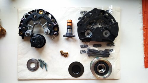
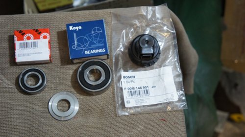

I remove the old bearing, everything is quite commonplace, with an ordinary small puller. And I get to the slip rings.
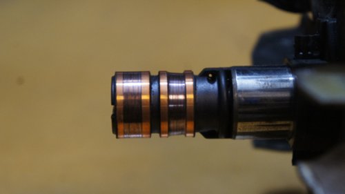
The condition of the lower ring is very worn
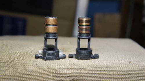
For comparison, old and new slip rings.
In order not to damage the rotor winding wires with a grinder, I cut off the petals at the base of the old slip rings, the rotor winding leads are attached to these petals by welding.
Lobes with rotor winding leads
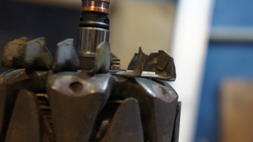
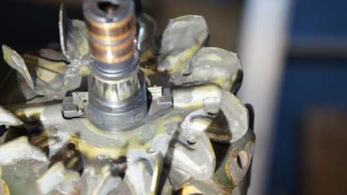

Cut petals with a grinder
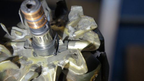
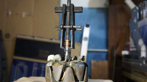
After carefully using a thin tool, I remove the leads with pieces of petals from the plastic base and, using a small puller, I press out the old slip rings.
Pressing out slip rings
Next, access to the terminals of the winding opens, carefully separating the remnants of the petals from the terminals. I do this very carefully so as not to damage the copper conductor. And I get this picture:
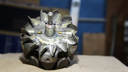
After pressing out the bearings on the rotor axis, there was a slight corrosion, which was easily removed with 2000 sandpaper.
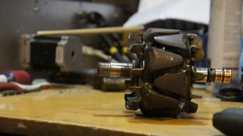
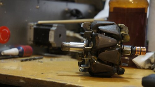

Then, after painting, I clean all the contact points on the generator case.
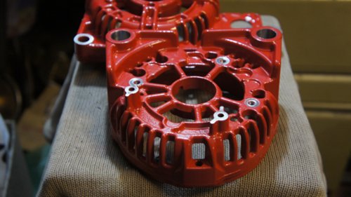
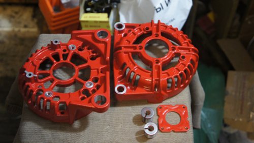
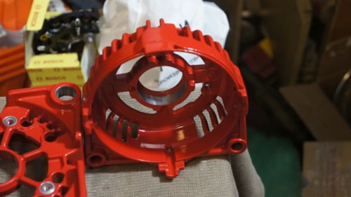
I install the boot of slip rings and brushes after cleaning the seat.
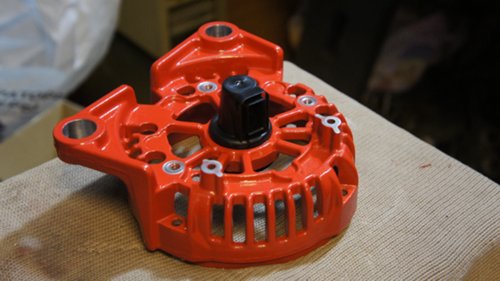
I install the stator winding into the case and thread the winding leads into the mounting rings of the diode bridge, which is fixed on top of the case.
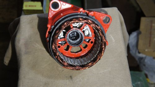
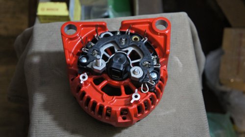

Next, I put on the bearing cap, the bearing itself and press a new washer on top.
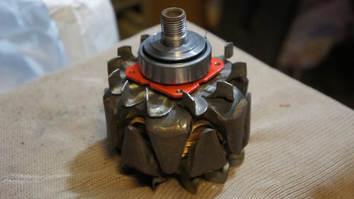
Installing new slip rings is simple, lightly tapping them in place, not forgetting to start the rotor winding leads at the base. There was welding from the factory, unfortunately I still have no opportunity to repeat the factory solution, so I soldered everything well.
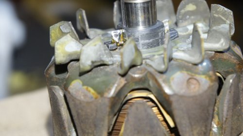
Pressing in a new bearing
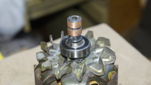
Similarly, with the rotor leads, I solder the leads of the stator winding with the leads of the diode bridge. I install the rotor in the generator case. With a little effort, the bearing comes into its rightful place and I screw on the brushes with a stabilizer. I close it with a protective cover.
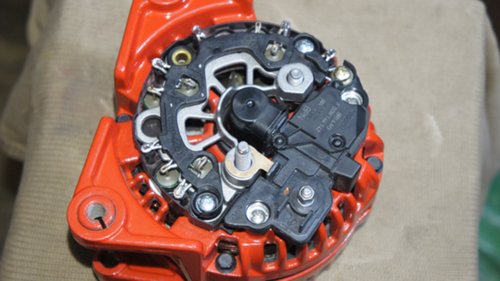
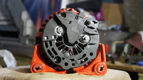

And finally, I install the overrunning clutch with a boot. The clutch is tightened according to the manual with a torque of 85 Nm.
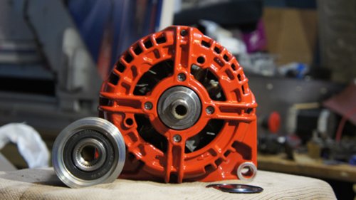
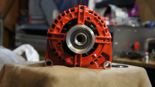

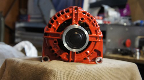

Slaffko, hammer.
why did you choose this color?
Slaffko, hammer.
How much did it cost?
why did you choose this color?
you know one cost of the voltage regulator ?!
Py.Sy. generators that go higher without an overrunning clutch, and this is +1200 UAH
go nuts prices
Everything was bought for the bulkhead:
Tilki durish of our brother!)
and it was not easier to prikolhozit generator with omega 3.0 new for 2000 UAH?
Tilki durish of our brother!)
2.
F 00M 123 318
Mіst dіodny generator
15
F 00M 144 142
Alternator spring regulator
Before the speech-regulator springs, it’s hard to know in sales.
Sorry I'll fix it, by the way, the regulator here is still an old model for a nut, they went until 2006, then they go under the clam. There are several Bosch numbers.
and it was not easier to prikolhozit generator with omega 3.0 new for 2000 UAH?
I also have a new starter from 3.0 for UAH 1,500, but I can't put it in))))
the regulator here is still an old model for a nut, they went until 2006, then they go under the clem. There are several Bosch numbers.
absolutely true to the soul!)
that scho pid clem vartu in the region 2 kg.
Modified: Eustace, 26 Feb 2016 - 09:56
A grandiose bulkhead. Recently I myself have been studying the gene, but on a smaller scale.
Why was it decided to replace the diode bridge?
Why was it decided to replace the diode bridge?
I think not to climb there anymore
And kinte pozh. a photo of the old diode bridge!
And kinte pozh. a photo of the old diode bridge!
Sergei, is he different with us? Or do you want to experiment?
I think not to climb there anymore
Then the rotor could still be bought.
Sergei, is he different with us?
That's what it seems that it is not different, and old age (wear and tear) interests!
Then the rotor could still be bought.
That's what it seems that it is not different, and old age (wear and tear) interests!
if you have 100 worth it, maybe this one, but I doubt it.
I have a 120th from the factory
That's what it seems that it is not different, and old age (wear and tear) interests!
There are such suspicions that with aging, diodes in the bridge begin to break through, but this is only a hypothesis. I haven’t replaced the bridge yet, I was getting undercharged. Bug managed to fish out only with an oscillograph with a load of genes on a ballast:
Therefore, there is such interest.
In general, the vehicle, I overdid it with replacements, it makes no sense to change the regulation, the brushes - yes. It will not be worse, but the cost of the issue will become commensurate with the cost of the new gene.
Modified: NNN, 09 Mar 2016 - 09:46
A grandiose bulkhead. Recently I myself have been studying the gene, but on a smaller scale.
Why was it decided to replace the diode bridge?
I think not to climb there anymore
To the point, since leaving the old one did not see the point.
And kinte pozh. a photo of the old diode bridge!
Unfortunately, he is already far from me, in the junk. It is exactly the same as in the photo. Only overgrown with moss and oxidized)))
Then the rotor could still be bought.
The rotor is in excellent condition, what's the point? I wouldn't change the stator either, but the insulation began to slip off the windings.
In general, the vehicle, I overdid it with replacements, it makes no sense to change the regulation, the brushes - yes.
There is a sense, since I changed it.
The body of the regulator was completely cracked, the outlet was holding on to the snot due to corrosion. If you also disassemble to replace the brushes, you can completely forget about the tightness of this device.
There are such suspicions that with aging, diodes in the bridge begin to break through, but this is only a hypothesis.
Either one or two diodes were punctured, I don't remember exactly.
if you have 100 worth it, maybe this one, but I doubt it.
I have a 120th from the factory
If my memory serves me when I was looking for the item. then the bridge and the regulator beat the same at both 100 and 120.
The rotor is in excellent condition, what's the point? I wouldn't change the stator either, but the insulation began to slip off the windings.
There is a sense, since I changed it.
The body of the regulator was completely cracked, the outlet was holding on to the snot due to corrosion. If you also disassemble to replace the brushes, you can completely forget about the tightness of this device.
There you just have to undermine the sryshchechka, knock out the compound in the brush compartment.
The tightness of the rest of the units is not violated. Brushes sold separately. It only needs flux to solder to the aluminum contacts and epoxy to re-seal.
Either one or two diodes were punctured, I don't remember exactly.
Ringing in both directions, disconnecting completely.
There you just have to undermine the sryshchechka, knock out the compound in the brush compartment.
The tightness of the rest of the units is not violated. Brushes sold separately. It only needs flux to solder to the aluminum contacts and epoxy to re-seal.
Just the same the case was damaged, the corrosion of aluminum ripped open the plastic and cracked it. Therefore, it was decided to change everything in bulk.
Slaffko, is there a key for the clutch? I need to change the big bearing behind it))))
Slaffko, is there a key for the clutch? I need to change the big bearing behind it))))
Voltage Regulator Part Numbers;
HUCO 13 0601 with a contact for the connector (chip);
BOSCH F 00M 144 142 with a contact on a threaded connection (nut);
CARGO 333273;
AS ARE0067;
WAI IB160.
Brushes;
BOSCH 1127014028;
KRAUF AHB2132;
CARGO BX 2132;
IKA 0.1065.1.
Diode bridge and voltage stabilizer bolt:
CARGO 230777;
Check before ordering for compatibility with your generator model!
Once again, after a season of deep puddles, I change the bearings of the generator. I decided to show how I did it, maybe someone will come in handy. I have a Z18XER engine, a BOSCH 100 generator. Let's start. Remove the negative terminal from the battery using a 10 key. We jack up the front right side of the car, remove the wheel. We remove the mudguard. To do this, using a thin object (for example, a nail) push the cores of the clips inward, look where they fall and take out the clips.
Then, using the TORKS T-25 sprocket, unscrew one screw from the side of the wheel, and three screws from the bottom
If you are not going to change the alternator belt, it is recommended to make marks on the belt so as not to change its direction of rotation
After that, we remove the belt. To do this, we loosen the screw that secures the tension roller, loosen the roller itself with a 19 (ordinary twelve-sided) spanner and insert a retainer into the hole in the tensioner (a rod of a suitable diameter, again a nail)
Next, use the TORKS E-14 head to unscrew the two screws securing the generator
We remove the generator, turn it over with its back side towards us
and first remove the connector from the relay-regulator, having previously moved the latch lock (blue plastic part) towards the cap
then, unscrewing the nut (key 13), terminal B2 +
Next, we take out the generator. I did not manage to pull it out right away, I turned it around for a long time in search of a suitable position
Let's add to the disassembly of the generator. We unscrew the two nuts (13 and 15) on the back of the generator and remove the plastic cover
Then, by unscrewing the three fastening screws, we remove the relay-regulator.
Holding the pulley through the gasket with a gas wrench, unscrew the pulley fastening nut (with a 24 head) and remove the pulley
With a head 8 or a Phillips screwdriver, unscrew the four screws and disconnect the back of the generator together with the stator from the front
Having unscrewed the four bearing fastening screws, we remove the front part of the generator housing from the bearing (when I changed the bearings for the first time, I took it off with a puller, the second time I got off myself)
Next, remove the front bearing with a puller
at the end of the rotor I do not know what the slots are made for
and therefore the puller rod wedges.To avoid this, I placed a thick washer between the puller rod and the end of the rotor (see above)
The rear bearing fails quite rarely. In order to remove it, you need to sharpen the puller rod so as not to damage the plastic element of the manifold.
Well, that seems to be all for disassembly. Here is the disassembled generator
dimensions 47x17 t = 14 fits from the VAZ dozen (I don't remember from an old or new generator)
rear
dimensions 35x17 t = 11
That Vologodsykh, that SKF suffices exactly until the moment when big puddles start on the street, I think because the gaps between the cleat and the engine compartment are too large and the water from under the wheel pours directly onto the generator.
There were no complaints about the electrical part of the generator, so I did not check anything in this area
It remains to assemble everything in the reverse order, set up a calendar with a clock and power windows.
Everything . Good luck!
Last edited by gennadiy2501 on Fri May 18, 2012 18:31, edited 1 time in total.
Here is a photo if interested.
And here is the Huco catalog number 13 0573
I don’t know about the reliability, but the bolts are the same.
Your instructions helped me a lot in preparation for the preventive generator bulkhead.
Thanks!
After disassembling, I noticed greenish growths at the base of the B + contact bracket.
I shook this brace, and it fell off at this very base.
Naturally, I cleaned out the remaining stub and soldered the molded new terminal.
Before building, I did the following:
1) enrolled all the contacts for fixing the diodes and the terminals of the stator windings, and soldered them
2) cleaned the heatsink of the voltage regulator (on the back)
3) cleaned and sprinkled all contacts ‘under the screw’ and their seats on the case with oil for contacts
4) additional grease LM50 was applied to the bearing of the front end (graphite can be used)
5) when assembling the case, I processed all the screws with graphite
By the way, instead of a regular pulley, I installed a freewheel pulley.
Let's see how it behaves.
Before installation, on the rear housing of the generator, I slightly pressed the 2 cut threaded bushings in order to make it easier to drive the generator to the regular mounting place.
Installation was complicated by the fact that it was necessary to position the generator in the place of attachment with one hand, and rest on the brake disc of the wheel with the other hand.
The result of the bulkhead was unexpected.
If earlier the established voltage (after turning on / off low-power consumers) rose to 14.7-14.9V after starting the engine, now it does not jump above 14.4V and does not fall below 14.2V.
PS: In addition, I cleaned the belt from small stones that were pressed into the rubber, and lubricated the case and the belt tensioner spring. And then the plastic wrap of the case under the spring was already a little rubbed (characteristic marks), which indicated that there was friction.
5. Remove the three screws securing the voltage regulator with the brush assembly.
b. ... and remove the voltage regulator with the brush assembly.
It looks like a voltage regulator with a brush assembly, removed from the generator.
Check the free protrusion of the brushes. If H is less than 2mm, replace brushes or brush assembly. Check the ease of movement of the brushes in the brush holder. If it wedges, the brush assembly must also be replaced.
7. Open the crimped terminals of the rectifier unit with a screwdriver until the ends of the six leads of the stator windings are completely free.
The photo shows three terminals of the stator windings. The other three outputs are located symmetrically on the rectifier unit.
The stator winding terminals consist of three wires each.
8. Remove the two screws securing the rectifier unit.
The third screw for fixing the rectifier unit, with which the protective cover is attached at the same time, was removed when the cover was removed.
9. . and remove the rectifier unit.
10. Mark the relative position of the stator and generator covers.
11. Remove the alternator pulley from the rotor shaft (see "Replacing the alternator pulley", page 210).
12. Remove the four tie bolts.
thirteen. . and remove the cover from the side of the slip rings from the centering sleeve of the rear bearing of the rotor shaft.
14. Inspect the cover from the slip ring side. If cracks in the cover are found, especially in the places where the generator is attached, it is necessary to replace the cover with a new one.
15. Gently pry the stator with a screwdriver and separate the stator and cover from the drive side.
16. Remove the four rotor shaft front bearing retainer plate screws.
17. Press the drive end cover off the front rotor shaft bearing.
In order not to damage the threaded shank of the rotor shaft with the screw of the puller, screw on it the nut that secures the pulley flush with the end of the shaft.
19. Remove the spacer from the front end of the rotor shaft.
twenty. . and from the rear bearing of the rotor shaft, a centering sleeve.
21. Inspect the plastic centering sleeve of the rotor shaft rear bearing. The centering sleeve must be firmly seated in the hole in the cover. If the bearing is properly seated in the sleeve, there should be no traces of slippage in the outer ring of the bearing.
22. Inspect the front rotor shaft bearing. If during the rotation of the bearing you feel a play between the rings, rolling or jamming of the rolling elements, damaged protective rings or grease drips, replace the bearing. To replace the bearing, press it off the rotor shaft with a universal puller. Press the new bearing onto the shaft, applying force only to its inner ring.
Pressing on the bearing by applying force to its outer ring will damage the bearing.
23. Inspect the rotor shaft rear bearing. If during the rotation of the bearing you feel a play between the rings, rolling or jamming of the rolling elements, damaged protective rings or grease drips, replace the rotor, since the non-removable block of slip rings does not allow the bearing to be pressed off the rotor shaft.
24. Inspect the slip rings. If they have scuff marks, risks, scratches, wear marks from brushes or other damage, the rings must be sanded. If the damage to the rings cannot be removed with sandpaper, you can grind the rings on a lathe, removing a minimum layer of metal, and then grind.
25. Check the resistance of the rotor winding with a tester by connecting it to the slip rings. The resistance should be approximately 3-5 ohms. If the tester shows infinity, then there is an open circuit in the rotor winding - the rotor must be replaced.
26. Check the absence of a short circuit between the rotor winding and the case by connecting the tester leads to any slip ring and the rotor case. The tester should show infinity.
27. Check the stator winding for an open circuit, alternately measuring the resistance between all winding leads with a tester. If the measured resistance tends to infinity, then it is necessary to replace the stator.
28. Connect the test leads of the tester to the stator housing and alternately to each winding lead. The measured resistance should be very high (tend to infinity). Otherwise, replace the stator.
29. Check the "positive" diodes by connecting the "negative" (black) tester probe to the "plus" terminal of the generator, and the "positive" (red) probe alternately connecting to the three contact terminals of the diodes. If the diodes are good, the tester will show 500-700 ohms.
30. Connect the "positive" (red) probe of the tester to the "plus" terminal of the generator, and the "negative" (black) probe alternately connect to the same three pins of the diodes. If the diodes are good, the tester will show an infinite resistance.
31. Check the "negative" diodes in the same way, connecting the tester probes in the same sequence as when checking the "positive" diodes.
32. If the tester shows low or close to zero resistance, the diode is "broken"; if the tester's reading tends to infinity regardless of the color of the connected probes, the diode is “open-circuit”. In both cases, the rectifier unit must be replaced.
33. Assemble the generator in the reverse order of disassembly, orienting the generator covers and stator according to the previously made marks.
After disassembling the terminals of the rectifier unit (see item 7 above in this subsection), after installing the terminals of the stator windings in them, squeeze the terminals of the stator windings with pliers or pliers until there is no movement of the wires of the terminals in the terminals.
Removal and installation of the generator
- Activate the parking brake, jack up the front of the vehicle and place it on the struts. If equipped, unscrew the fastening screws and remove the engine crankcase guard. Disconnect the negative cable from the battery.
- Remove the air cleaner housing and intake air ducts assembly with the MAF sensor (see the Chapter Power supply and exhaust systems).
- Loosen the alternator drive belt (see Chapter Ongoing maintenance) and remove it from the alternator pulley.
- Remove the mounting bolts and remove the generator mounting bracket to the intake manifold.
- Remove the mounting bolts and remove the generator mounting support bracket on the cylinder head. Tilt the generator back.
- Release the electrical wiring from the clips and remove the bracket.
- If equipped, remove the rubber protective caps from the generator terminals, loosen the fastening nuts and disconnect the electrical wiring from the back of the generator.
- Remove the lower mounting bolt, lift the generator up and out of the engine compartment.
Engines 1.4, 1.6 and 1.8 l DOHC
1 - wiring
2 - the upper bolt of fastening of the generator
3 - lower bolt of fastening of the generator
4 - SKR sensors
5 - oil pressure sensors
- Keeping the tensioner spring in the charged state, remove the accessory drive belt from the pulleys (see Chapter Ongoing maintenance).
- Remove the air cleaner (see Chapter Power supply and exhaust systems).
- On the models 1.8 l disconnect the wiring from the camshaft position (CMP) sensor and remove the connector from the support bracket.
- Remove the upper bolt of fastening of the generator (see illustration Disconnecting the electrical wiring).
- Loosen the lower mounting bolt and tilt the generator back.
- Remove the mounting bolt (s) and remove the alternator drive belt tensioner (see. Removing and installing tensioner drive belt generator).
- On the models 1.8 l disconnect the electrical wiring from the crankshaft position (CKP) and emergency oil pressure sensors. Take the tourniquet to the side.
- If equipped, remove the rubber protective caps, loosen the retaining nuts and disconnect the wiring from the back of the generator.
- Remove the bandages securing the generator bracket to the cylinder block and remove the generator. On the models equipped with K / V, the generator is removed downward.
- Remove the air cleaner housing and intake air ducts (see Chapter Power supply and exhaust systems).
- Keeping the tensioner spring in the charged state, remove the belt from the pulleys (see Chapter Ongoing maintenance).
- On models without air conditioning, remove the alternator drive belt tensioner (see. Removing and installing tensioner drive belt generator).
- Remove the mounting bolts and remove the generator mounting brackets from the intake manifold and cylinder head.
- If equipped, remove the rubber protective caps from the generator terminals, loosen the fastening nuts and disconnect the electrical wiring from the generator.
- Remove the three bolts securing the generator bracket to the cylinder block, remove the generator with the bracket by lowering the assembly down.
- Remove the mounting bolts and separate the bracket from the generator.
Installation is in the reverse order.
- Make sure that all fasteners are tightened to the required torque. Adjust the tension of the drive belt (see Chapter Ongoing maintenance).
- Activate the parking brake, jack up the front of the vehicle and place it on the struts. If equipped, unscrew the fastening screws and remove the engine crankcase guard. Disconnect the negative cable from the battery.
- Remove the air cleaner housing and intake air ducts assembly with the MAF sensor (see the Chapter Power supply and exhaust systems).
- Loosen the alternator drive belt (see Chapter Ongoing maintenance) and remove it from the alternator pulley. Remove the mounting bolts and remove the generator-to-intake manifold support bracket.
- On the models without K / V Unscrew the tensioner guide rail fixing bolt and remove it together with the adjusting nut. Remove the retaining bolt and remove the guide plate from the cylinder head.
1 - Bolts of fastening of the upper bracket
2 - the Adjusting bolt
3 - the Nut of the adjusting bolt
4 - Adjusting bar
- On the models with K / V unscrew the mounting bolts and remove the generator upper support bracket.
- If equipped, remove the rubber protective caps from the generator leads, loosen the retaining nuts and disconnect the electrical wiring from the back of the generator.
- Remove the bolts securing the generator support bracket to the cylinder block, lift the generator up and remove it from the engine compartment. If necessary, the generator can be separated from the bracket by loosening the nut and removing the mounting bolt.
5 - Generator
6 - Support bracket
- Keeping the tensioner spring in the charged state, remove the accessory drive belt from the pulleys (see Chapter Ongoing maintenance).
- If equipped, loosen the fasteners and remove the crankcase guard.
- Unscrew the fastening bolts, disconnect the electrical wiring and remove the horns of the horn (see the Chapter Onboard electrical equipment).
- Disconnect the supply pipe from the vacuum pump located behind the generator, disconnect the oil return pipe, - prepare to collect the spilled oil.
- Remove the upper and lower mounting bolts and remove the generator assembly with the vacuum pump through the opening created after removing the horns.
A - Upper alternator mounting bolt
B - The lower bolt of fastening of the generator
- Despite the fact that the vacuum pump can, in principle, be separated from the generator, at the time of compilation of this manual, none of the components were individually supplied to the spare parts market - if necessary, contact the specialists of the Opel service station for advice.
- Remove the air cleaner housing and intake air ducts (see Chapter Power supply and exhaust systems).
- Keeping the tensioner spring in the charged state, remove the belt from the pulleys (see Chapter Ongoing maintenance).
- Remove the starter and turbocharger heat shields and loosen the lower generator mounting bolt.
| Video (click to play). |
1 - the Bottom bolt
2 - the Upper bolt
3 - a Hose of a cooling path

