In detail: do-it-yourself repair of the yppd j017c hybrid from a real master for the site my.housecope.com.
SAMSUNG LE32B450C4W Unnatural coloration.
Akira LCT-32MT02ST
When turned on, there is no image, there are 1 or 3-4 vertical stripes of different colors on the screen, there is sound, control works, ice blinks on the SSB lane.
Cause: on T-con 3.3v is overestimated. up to 3.9v. and the absence of 2.5v. (0.6v.), after replacing the stabilizers ASM1117-3.3 end ASM1117-2.5 everything worked.
Viewsonic N3260W
SP FSP228-4F01 SP was already repaired a year ago, pretty much plowed, at the moment there is a standby mode, but 12V is understated in the working one. up to 8V. and 24V. up to 14V. The PFC type does not fully start - after replacing the UCC28051 and FS10SM (there was a BUZ90 after the previous repair), the IP started working and of course the TV.
LCD BBK LD2006SI Vertical colored stripes + black stripe in the middle.
Plasma SAMSUNG PS-42V6SR noise in the image.
percent LGE6891DD-LF
matrix PDP42G10001
malfunction; the image strongly adheres and doubles; the horizontal green stripes are faintly visible.
the reason turned out to be in the logic board. below photo.
Chinese TV LCD SAMSUNG LA-81B
there was no image, the power to the regulators is excellent, the power to the T-CON is supplied
checking the power supply on the T-CON I did not see the sealed resistors R40 and R41 4.7kom, SEE IN THE PHOTO. For some reason, the resistors did not hold the soldering, so I put others.
and the image appeared.
Lifting the hybrid YPPD-J017C (PDP 42V8) on discrete units. LG, Toshiba, Philips, etc., assembled on the basis of the LG 42v8 PDP panel.
We used IRFS4229PBF transistors (45A, 250V, RDS (ON) 42 mOM, Key Parameters Optimized for PDP Sustain). The gate resistors need to be replaced even if they have not leaked (yet). Do not install diodes (drain-sources) - available in IRFS4229PBF.
These transistors were also used for PDP 42V6 repairs (7).
| Video (click to play). |
LCD TV & DVD "DAEWOO" DSL-20M1TC Received for repair with a declared defect - there is no channel tuning.
Searching for no yielded nothing, except for requests to buy the tuner M09WPP-1P-E.
Power supply and quadrature are normal, at the V output there are chaotic noises. He did not react to deformation, when tapped, the snow blizzard clearly changed. The tuner was dismantled and soldered by a bulldozer under the optics. No changes.
I set the working frequency of the channel in the manual setting, tapped - nothing. I remembered the flow of solder under the quartz leads, carefully squeezed it from the varnish. And here it is happiness. Soldered - the holes in the gasket under the quartz are too large and filled with solder.
The MPE05-1-E tuner has the same pinout - the protocol is questionable.
Warnings: 1
Posts: 28
Warnings: 1
Posts: 28
yes indeed the boards cost 6871 and not 6870, they are embossed on white tags.
YSUS 6871QYH036B
ZSUS 6871QZH041A
CSUS 6871QCH053D flash firmware (from 050407 firmware name: 42V73LV3B)
Panel PDP42V74062, 504K342V7006876.ASLGB.21, p / n 3315Q-E037F, made in korea.
Photos of boards, their part numbers and a burnt out hybrid.
Warnings: 1
Posts: 28
Warnings: 1
Posts: 28
Brainstorm
Posts: 3622
Warnings: 1
Posts: 1494
slowolitus, here is a clipping from the SMD catalog, diodes marked “45”, maybe these are the ones you are looking for?
Code Device Manufacturer Base Package Leaded Equivalent / Data
45 BAT14-055S Sie CS SOT173 8GHz schottky diode
45 BAT14-055R Sie CZ SOT173 8GHz schottky ring quad
And what diodes would fit, since FRD1, FRD2 are in the pot?
And by the way, there are only two transistors. .?
Q3, Q4 are integers, can only Q1, Q2 be changed?
I immediately discarded the wiring, the diodes are 100%
dead, so what kind of diodes can you substitute?
I use field workers from broken Y-SUS boards from 42V8.
If 45N25, then 45A and 250V, search for RF parameters by datasheet.
About not exactly the same - did you solder them?
Here is a schematic diagram for repairing a Z-SYS 42-inch LG chassis.
Probably suitable for Y-SYS as well.
While I tried various transistors, I burned 20 pieces.
As a result, I found out that only high-speed IGBTs with operating frequencies of 150-300 kHz are suitable.
It replaces half of the native hybrid from LG.
Only one part burned out, so I sawed off the non-working part with a hacksaw and replaced it with this scheme. The transistors are naturally attached through the NOMAKON gasket and coated with KPT-8 paste on both sides. On the radiator, I additionally screwed an 80 * 80 mm fan and connected it to +9 volts of the TV's power supply.
Schematic and print in P-CAD 2006
For the first time, the conductors going to the power transistors burned out on this printed circuit board. so when repeating it is necessary either to redistribute the board or to solder wires on top of the conductors on the board.
If you do not solder over the seal, then the conductors burn out when turned on.
The VD5 diode according to the scheme is any high-speed one for a current of about 1-2 amperes and a voltage of more than 300 volts. HER105 diodes are also suitable.
All ceramic capacitors for a voltage of at least 25 volts.
In general, if anyone is interested, ask. I will tell you!
The TV is still working properly


LG - 42PC1RV-ZJ
Something clicked the screen went blank. The sound is on the remote control.
The question is this:
What could be the reasons and the cost of the repair. And in general, is it worth repairing it? TV is 5 years old
Thank you.
Do you write to the workshop? : de_vil:
And in general, is it worth repairing it?
Can't decide for yourself? Do you think you know better at a distance?
Are we going to repair it or let it work?
"A person cannot be helped against his will." G. Pomerants
alexarg Can't you raise this TV if you don't know how plasma panels work? And so check out the hybrid, ignition, etc., etc. : Co_ol: If you find a dead fuse for powering the hybrids, then do not try to put a beetle there, or even the MAIN block will be finished by feedback. For such a repair, not every master will take it, but you are here (what could it be?) 🙂
The source of our wisdom is our experience. The source of our experience is our stupidity.
yes, in general, I myself was not going to climb
the question is the profitability of the repair.
called the office. service (I live in Spain) where the operator takes orders and knows nothing.
call a technician or shove him over 30 km. That is why I am consulting about possible reasons.
I don't need full details.
alexarg It all depends on the cost of the service for such a repair + the cost of parts. In general, half the price of the cost of TV comes out about us, if it is done according to the mind. Hybrids don't just fly off, there are still a lot of nuances that need to be replaced.
The source of our wisdom is our experience. The source of our experience is our stupidity.
In general, it is not profitable, the TV is 5.5 years old, I already bought a new one, it’s just a pity to throw out 1000 euros then I gave it for it.
He asked self-taught, not Petrosyans, knowledgeable ones.
alexarg, I did not try to amuse someone at all. I wanted to make it clear that one had to think first, and only then write. Magicians in fairy tales.
Are we going to repair it or let it work?
"A person cannot be helped against his will." G. Pomerants
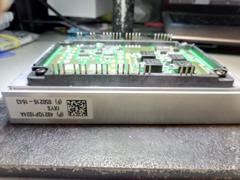
This is what the hybrid looks like. The bottom photo shows fried field workers.
The source of our wisdom is our experience. The source of our experience is our stupidity.
read the essence of the question more attentively.
I read this before: https://my.housecope.com/wp-content/uploads/ext/3569/forum/viewtopic.php?f=29&t=4459, followed by “the essence of the question”, I decided to write. I beg your pardon, I did not realize how all this is connected.
We know these - there is a plug in every barrel
I expected that there would be something about “our brother”, I had already prepared an answer: “I have no brother,” but here about a barrel, we are looking at the link. About the plug: You, apparently, were mistaken - I'm not a moderator.
As you can see, no. I write and read in "Consulting Clients". Let me draw your attention to the titles of the sections. : dr_ink:
Are we going to repair it or let it work?
"A person cannot be helped against his will." G. Pomerants
I have LG - 42PC1RV-ZJ PDP V80201
Zsys 6871QZH053B
WL 42065KO30884
Ysys 6871QYH048Y
Today the image suddenly disappeared.
The sound is on the remote control. Where is this hybrid, if that's the case? I took off the back cover I thought the fuses are all intact. Two per game board two per zet board. I read on the forum that it is possible due to the lack of 15 V, but I can not find them where they can be either. At what points to watch the oscillograms tell me and what should be.
Warnings: 1
Posts: 204
my.housecope.com/wp-content/uploads/ext/2255
Posts: 10109
Warnings: 1
Posts: 1
Iron Reindeer Herder
Posts: 11260
Warnings: 2
Posts: 76
Good to everyone.
mastered the topic
hybrid YPPD-J017C (PDP 42V8), Q4 kz-question. what to replace?
https://my.housecope.com/wp-content/uploads/ext/2255/forum/files/yppd-j014c_110.pdf
the scheme is not even anything, the denominations are not enough

a good person advised, replaced all 4 transistors, "flight" is normal. There are goose bumps on the left, probably from "old age", the temperature is a little over 70 degrees.


PS another one came, I'll tell you right away, change all 4 pieces, if Q3 or Q4 is broken, usually the last one
there is another function in the menu, “low. power"
the temperature does not rise above 55
The hybrid from the first page of this topic has worked for almost 7 years. This time, Q12, Q13 and two of the four transistors I installed burned out. Probably because of the SMD resistor blade in the gate.The solder became loose because I added Wood's alloy to make soldering easier.
LG RT-42PX11. A variant of the restoration of the PDP42V6 hybrid using two IXTA60N20T transistors. Heating is normal, there are no goose bumps. The temperature of both modules drops noticeably when the “low power” mode is enabled in the menu.
Hello earthlings and aliens


also faced plasma with 42v6
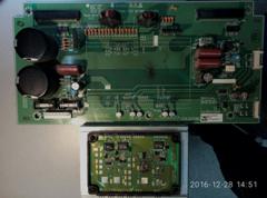

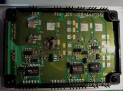

and after my playful little hands it became like this
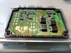
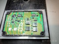



Of course, the causes of this misfortune were eliminated, namely, the power supply for controlling the opening of these transistors was restored.
Surprisingly, everything that was in front of the field workers remained alive, except for the resistors in the gates of the IGBTs. Field workers 36N30 (36A 300V) were supplied instead of IGBTs
PS I put transyuchki on pos61, I didn’t use muds, but why?


Lg ... ZSYS with part number 6871QZH033A
Pay attention to 15 volt power supply. When it sinks (usually up to 12 volts), the hybrid dies.
Replacement for IXTA36N30P shown. Resistors in gate circuits are installed 4R7. Although it looks like "no ice", but it has been working for 2 weeks already, The heating of the radiator is a little less than Y-sus .—–
Info taken from my.housecope.com/wp-content/uploads/ext/2255
Classic malfunction. Failed hybrid microcircuit on the Z-sys due to understated supply of the DC / DC converter 15 v on the Y-sys.
In the hybrid, the caseless transistors Q12-Q16, resistances R3, R4, R10 (5.6 om), diode D22, D23 are out of order.
The transistors were replaced with IGBT XTA 6N20 from IXYS and the diodes were replaced with simple SMDs marked 25.
I took all the parts from disassembly, a dead Y-sys panel 42V7.
After turning on, the image showed "goosebumps" all over the screen. The total mowing of the litas on the Y-sys and a slight adjustment of the upper (set_up) and lower (set_dn) platforms solved the problem.
Info taken from my.housecope.com/wp-content/uploads/ext/2255
Some more information on the YSUS module.
At one time, when ordering this module for garment devices, LG first supplied 6871QYH029A, and later - 6871QYH029J. The difference between these two modules is insignificant - in capacities. In the 6871QYH029J module, a number of containers were replaced with others at the factory. Here they are:
1.C18 with 33 uF * 25v (in the 6871QYH029A module) is replaced by 470 uF * 25v (in the 6871QYH029J module),
2.C24 with 220 uF * 25v (in the 6871QYH029A module) is replaced by 470 uF * 25v (in the 6871QYH029J module),
3.C35 with 100 uF * 16v (in the 6871QYH029A module) replaced by 220 uF * 25v (in the 6871QYH029J module),
4.C19 with 33 uF * 25v (in the 6871QYH029A module) replaced by 220 uF * 25v (in the 6871QYH029J module),
5.C33 with 220 uF * 25v (in the 6871QYH029A module) is replaced by 1000 uF * 25v (in the 6871QYH029J module).
Here are the pictures of the modules. The first is the 6871QYH029A module, the second is the 6871QYH029J module.
Info taken from my.housecope.com/wp-content/uploads/ext/2255
Articles, reviews, prices for machines and components.
It is allowed to publish offers for the purchase / sale of both individuals and commercial organizations, subject to the following conditions:
1.the characteristics of the goods must be present
2.the cost of the product or service must be present
3. there must be a description of the methods of payment and delivery
4.one seller - one topic
Photos of goods are welcome (photos must be attachments to messages).
It is possible to place a link to your website, with a description of the goods, subject to the mandatory observance of paragraphs 1-3.
The forum administration can delete a topic or messages from this section, without giving any reason!
Attention, the general section is closed for creating new topics! Create themes in profile sections (Buy, Sell, Services)!
I offer new and original modules at a bargain price. Quality guaranteed, 90 days warranty. I am in St. Petersburg. The price and availability can be clarified by calling (+7 921 8848160) or by writing to the mail (), I will answer on the same day. To save your time, please indicate in your request how many pieces you need and where you are geographically located.
There are also IGBT modules, thyristors and diode bridges, various powerful semiconductors at wholesale and retail prices on order, more than 25,000 items.
Delivery to the regions by transport companies (Russian Post, EMS - at your expense). Payment for a platstic.
I will help you find modules, scarce boards, encoders for servo motors of various modifications, servo motors, native matrices for industrial monitors.
Last orders:
7MBR25SA120H-70
BSM25GD120DN2E3224
BSM35GP120
BSM50GD120DN2
BSM50GX120DN2
BSM100GB120DN2
BSM150GB120DN2
BSM400GA120DN2
CM75DY-24H
CP15TD1-24Y
CPV363M4F
FS100R12KE3
FSBB30CH60C
MG25Q6ES51
MG150Q2YS1
PM50CL1B120
PS21267-AP
SEMiX353GB126v1
SEMiX503GB126V1
SKD 145 16
SKiiP 13AC12T4V1
SKiiP 24NAB126V10
SKiiP 25AC12T4V25
SKiiP 25AC126V1
SKiiP 32NAB12T1
SKiiP 35NAB126V1
SKiiP 38AC126V2
SKiiP 39AC12T4V1
SKKD 81 16
SKKT 162 17E
SKM100GAL123D
Modules available (there are others):
In the plasma TV LG RT-42PX11, after a soft click, the image disappeared, while the sound remained. Studies have shown that the FS1 (4 A) fuse that protects the VS (+190 V) circuit on the ZSUS board (board number - 6871QZH033B) has burned out. Replacing the fuse-link did not lead to a positive result - after turning on the TV, it again failed.
Measurements of the resistance of the VS circuit line with respect to the common wire with an ohmmeter showed the presence of a short. The module (hybrid microcircuit) IC4 on the ZSUS board turned out to be faulty. After information about a similar malfunction [1, 2] was found on the Internet and the labor intensity and, most importantly, the probability of a positive result of the module repair [1, 3] were estimated, it was decided to replace the ZSUS board with a new one. By the way, the board with the above number is interchangeable with boards with numbers 6871QZH033A, 6871QZH033R [4, 5]. The first of them differs from 6871QZH033B and 6871QZH033R in the location of the РЗ connector, which is located close to the P2 connector [4]. On boards 6871QZH033B and 6871QZH033R, this connector is approximately 50 mm away from P2.Therefore, when replacing a board with one number with a board with a different number, you should pay attention to the length of board-to-board connecting wires suitable for the P3 connector.
However, even after replacing the failed ZSUS board, a working image did not appear - the screen remained dark. Further measurements showed that the voltage at the pin of the P3 connector of this board, designated "15V", is significantly underestimated instead of the nominal value of +15 V relative to the common wire - only about +9 V. This voltage feeds the microcircuit that is part of the IC4 module and the gate circuits open-frame IGBTs switching VS voltage A decrease in voltage apparently led to the fact that the switching transistors stopped opening completely, the voltage drop across them and, accordingly, the power released increased, which caused them to fail with a short circuit of the VS line to a common wire.
The +15 V voltage generates from the +5 V voltage generated in the TV's power supply a flyback converter on the LM2585S-ADJ microcircuit and a T1 pulse transformer located on the YSUS board (with the number 6871QYH029J). Its circuit is shown in Fig. 1 Positional designations of elements correspond to those on the YSUS board. It was not possible to find out the diode gypsum and the capacitance of ceramic capacitors for surface mounting, therefore they are not indicated on the diagram. A feature of the device is three independent channels for forming a stable output voltage of +15 V, and the negative terminals of two of them (connected to windings II and III) are isolated from the common wire of the TV.
The voltage is removed from the winding IV of the transformer T1, which rectifies the diode D66 and smooths the capacitor C72. From the output of the 1C 16 stabilizer, after smoothing by capacitors C21 and C29, the +15 V voltage is supplied to the ZSUS board. It also powers the 1C 12 module (hybrid microcircuit) of the YSUS board, similar to that installed on the ZSUS board. Therefore, you should make sure that there is no short circuit of the VS circuit to the common wire and to YSUS. If the 1C 12 module is faulty, it is better to replace this board as well.
Measurements using an oscilloscope showed that the level of ripple on the capacitor C72, even with the ZSUS board turned off, is excessively large - their swing reached almost 3 V. Using an attachment to a multimeter [6], the equivalent series resistance (ESR) of this capacitor was measured, it turned out to be 70 Ohm with a nominal capacitance of 33 μF. The reason for the underestimated voltage at the РЗ connector became clear - the ripple of the feedback voltage removed from the resistor R97, led to this result.
After replacing the capacitor C72 with another one (with a low ESR), the +15 V voltage was restored in all channels of the converter. To increase reliability, a 0.1 µF ceramic capacitor for surface mounting is connected in parallel to the oxide one: first, it was soldered to the printed conductors (as shown in Fig. 2), and already on top of it - the oxide one. In addition, due to increased ripple (about 0.5 V) at the input of the IC17 stabilizer, the oxide capacitor C203 had to be replaced (Fig. 3). Its ESR also turned out to be quite high - about 40 ohms.
And finally, the smoothing capacitors C57, C58 in the VS circuit demanded to be replaced, in which the bottom of the case was deformed (“swollen”) (Fig. 4). After these replacements, the image in the TV was restored. The reason for the increase in the EPS and the deformation of the capacitor cases is the increased heat release of the 1C 12 module, which is equipped with a ribbed heat sink. Therefore, during repairs, oxide capacitors should be used that can operate at elevated temperatures (usually there is an inscription “105 ° C” on their bodies).
1. ZSUS, YSUS hybrid replacement or repair? - https://my.housecope.com/wp-content/uploads/ext/2255/forum/viewtopic. php? t = 267993.
2. Plasma LG RZ-42PX11 - search for the ZSUS board. - https://my.housecope.com/wp-content/uploads/ext/2255/forum/ plasma-lg-rz-42px11 -zsus-info-178321. html.
3. PDP LG42PX10 unsuccessful hybrid repair. - https://my.housecope.com/wp-content/uploads/ext/2255/forum/ pdp-lg42px10-repair-info-283173.html.
4 LG 6871QZH033A ZSUS Board. - lg-6871 qzh033a-zsus-board.htm
5 LCD-Plasma Service. Inverter / Power Boards. - nl / content / LCDref.pdf
6. Glibin S. EPS meter - attachment to the multimeter. - Radio. 2011, no. 8, p. 19, 20.
- Slavik / 06/27/2018 - 15:39
Help me find (microcircuit: Yppd-j 04, 2300kcf 008 b-f) МTV: LG-42 px4Rv, Panel: 6871QYH036D, Ysus - Edward / 06/10/2018 - 18:08
please help me, my LV TV shows the floor of the screen clearly and the floor of the screen is dim, but you can see what it shows, what is the problem? - irina / 11/20/2017 - 11:05 pm
the image is gone but there is sound - Vladimir / 10.21.2017 - 08:39
the backlight of the plasma did not turn on on the lg42pt250 there is sound, it performs all the functions. At first it turned on from 3-4 times, but now maybe from 10-12 times and it works even all day, turn off the same story again. When it does not turn on, the LED does not blink on the board inside the TV when the screen starts blinking green. All voltages are normal on all boards. Tell me where to dig. - Nikolay / 06/16/2017 - 19:10
lj plasma TV 42rt250 does not light up the screen turns on from the buttons and from the remote control on the e52483 board 2 transistors 705 and 709 are punctured replaced the 15 volt understated voltage to 9v, - Victor / 01/18/2017 - 17:18
the TV is off and only the lamp does not turn on, the network blinks with increasing brightness - Alexander / 06/27/2016 - 14:53
comrades, good time. please tell me in LG RZ42PX10 it became dull to show the image, such as the matrix burned out! what could be the problem? - Dmitry / 02/04/2016 - 19:37
Guys, do not break the technique, give it to the good masters until you finish it off. - Nilolay / 01/05/2016 - 17:17
The image is missing, there is sound on the TV LG32LH540B-ZA - sharing / 05/07/2015 - 20:42
Water got into the TV and a black vertical stripe appeared on the floor of the screen. What to do. - Igor / 04/02/2015 - 00:48
the TV started flashing and jumping the image with black horizontal stripes across the screen - Evgeniy / 04.24.2014 - 08:54
Good afternoon, the LG 42LX6500 TV does not have a matrix backlight and it is not clear that it can work for a day, it turns on in the morning, it turns on and the backlight goes out after two minutes and then only when you try to turn it on again, it appears and goes out again, I'm not really a master in TVs, well, I don’t use my butts. fixing office equipment tell me where to dig - Vladimir / 04/08/2014 - 06:58
I wanted to see the scheme of the DNS S29DB1 TV, but I really liked everything that is there
You can leave your comment, opinion or question on the above material:
Fault description
Plasma turns on, there is sound, there is no picture.
Blown fuse on board YSUS... Since there was no short circuit, they replaced and turned on. The picture and sound is Va: 65V, Vs: 190V - corresponds, but the voltage of 15V is much lower. Replacing the capacitors in the 15v-converter circuits allowed 15V to be restored.
V preventive For the purposes of the YSUS board, almost all electrolytic capacitors have been replaced, ("aluminum") - everything.
Repair of LG TVs on 42V6 chassis was often found in the practice of telemasters.
Do not forget to bookmark this page on your social networks!
Darov to all figures, waxing the screen on the plasma panel went out, in a cursory examination it was revealed that the YSUS 6871QYH045D board is working
Sobsno photo -
Tantalum is not put into pulse circuits, they are afraid of exceeding the operating voltage very much, and pulses are even more so ...
Dear, I am throwing you a link, please read carefully, very carefully. It will broaden your horizons.
I hope in the future you will not make statements without understanding the issue.
The phrase “not understanding the issue” is very offensive, but in the case how much would a TV set cost if there were such tantals that could withstand the tension and impulses that are present there. As far as I understand, there is some kind of special series developed for these purposes. And the last question "not versed in the issue": why then they were not soldered there from the factory, huh? I here recently read some post by Stepan Palych, and so in it he wrote about the rejection of tantalum in his circuits in favor of ceramics as more reliable and withstanding the voltage for which they are designed, I somehow trust Palych more and not some manufacturer's website. This is my IMHO ...
There was no purpose to offend you.
There is no doubt who are Vishay (Conders), TI, Liner (ms. Imp. Converters) in our authority PALYCH!
You see, the use of ceramics or non-ceramics, films, etc. depends on many factors. Chip manufacturers often cite circuits for testing and debugging in the documentation, which are accompanied by a list of elements with their ratings and types. The use of the nominal values and types of elements specified in the documentation ensures that the circuit will correspond to the specified parameters in the same documentation. And which ones to apply to engineers, depending on the result they want to get.
They didn't solder it from the factory, I was mistaken, and when I took aluminum conductors for tantalum, I wrote it. They may not be soldered for two reasons, or tantalum is excessive (simply not needed), i.e. the piping of the converters is not critical to the type of electrolyte or economy.
Usually the second 🙂
In the plasmas of Panasonic, where the quality was treated properly from the factory, I never saw dead capacitors. And transistors in sustains are dying from improper operation, then it hangs in the bath, then the cat is pissed off, then something else.
I myself am doing PC repairs, but once they brought a plasma with a dead hybrid, the picture is the same as yours. Consulted professional TV repairmen. They said that the capacities in the power supply circuit of the hybrid should definitely be changed, and everything is better, and better for good solid state machines. So he posted. Everything started up successfully and works to this day.
So they die from very harsh working conditions, the capacitors dry up, the hybrid starts not working in the mode, warm up wildly and breaks down.
They have a common disease of these LG panels, they saved a lot on details.
I myself am doing PC repairs, but once they brought a plasma with a dead hybrid, the picture is the same as yours. Consulted professional TV repairmen. They said that the capacities in the power supply circuit of the hybrid should definitely be changed, and everything is better, and better for good solid state machines. So he posted. Everything started up successfully and works to this day.
Conders will change everything, then I will unsubscribe in a new topic, what happened there.
I myself am doing PC repairs, but once they brought a plasma with a dead hybrid, the picture is the same as yours. Consulted professional TV repairmen. They said that the capacities in the power supply circuit of the hybrid should definitely be changed, and everything is better, and better for good solid state machines. So he posted. Everything started up successfully and works to this day.
By the way, did you change these lumyakhi the same way? or in a shell?
changed to the same. exactly on solid bodies.
It is better to order by mail somewhere in a verified online store, there are a lot of them, and put the normal ones, which will work if you put them on, of course, but not for long and it is very likely that you will also burn new hybrids!
And flew again! Not only does this store wind up prices, they can also sell bullshit.
Well, let's see what they will send, if we have already ordered.
You can cancel the order, why overpay.
And flew again! Not only does this store wind up prices, they can also sell bullshit.
Well, let's see what they will send, if we have already ordered.
there are exceptions when a complete set is cheaper for them than even on Mitka
1pcs / lot YPPD-J018E = STK795-820 = STK795-821 = YPPD-J017 / 018C YPPD-J017C used for Y-type Sus Z-Sus board
RUB 269.13 New User Coupon
4% off (4 pieces or more)
4% off (4 pieces or more)
To United States by Singapore Post
The item does not ship to the selected country.
Unable to ship your selected address. Use the Filter on the list page to choose the product which can be ship to your country.
- Popular countries
- United States
- Russian Federation
- Spain
- France
- United kingdom
- Brazil
- Israel
- Netherlands
- Canada
- Italy
- Chile
- Ukraine
- Poland
- Australia
- Germany
- Belgium
- >>
- >>
To United States by Singapore Post
The item does not ship to the selected country.
Sorry, this item is currently unavailable.
Buyer questions and answers
If the item is not as described, you can return the item for return shipping charges, or keep the item and negotiate compensation with the seller.
Full refund if product isn't received in 60 days
Well, "hybrid", in appearance, just like an ULF microcircuit. As usual in such cases, I call the suppliers, so and so I say I need a detail.
It was then that they began to please me. First: the price. I also asked, is this not from the booster module of the Soyuz rocket? For the price of course.
Secondly: this microcircuit simply does not exist, and will not be. Something like it was released in a small batch, the whole batch went into action, there are no remnants. The question is, how can a part be produced in small quantities? Probably stepper motors are not used anywhere else. Directly exclusive released, some kind.
Photo lab makers are good too. Found what to put on control. After all, there are many other “controllers” of stepper motors available both in price and availability.
I realize I'm not going anywhere, I have to fix it. There is nothing to do, I find a datasheet on it, and read it. Repair is possible in principle. This makes me happy. But it was necessary to assemble such nodes on discrete elements. (I don't like this thing, in the sense of samizdat: feel :)
I carefully open the case of the "hybrid" and observe the installation, which is partially filled with sealant.
By the way, a disgusting thing. For two days, using his needle "karyabal" in the deadliest part of the microcircuit. "Dokaryabal". Dead four transistors. The main thing is to carefully remove the sealant. I decide to replace them with our KT972 and KT973. As the most affordable. You can see the result in the photo.
The operability is fully restored. The motor works with a bang. It is a pity that the process of "karyabanya" itself did not take pictures. I didn't think I would describe it.
I have now taken the pictures when this whole farm has been standing and working for a long time. But I think it's not scary. The essence is important. In the image and likeness, I think most of the rare "hybrids" can be reanimated.
For the repair of the "hybrid"
Soldering is extremely bad, the plate on which all this is assembled, the heat is taken away like a refrigerator. It was not possible to unsolder the crystals of the dead transistors, he crushed them with tweezers, only after that their landing site was tinned. I did not cover the place of repair with anything. I don't see the point in that.
That's all.
- master_tv
- Offline
- Moderator

- Electronics Repair Engineer
- Messages: 3613
- Thanks received: 246
- Reputation: -4
On QUANTA displays
LC4.1EAB 26PF3320 - no picture, vertical color and sometimes black thin horizontal stripes all over the screen.
Solution:
Modification of panels QANTUM.pdf
Samsung LTA320W2-L13 panel, T-CON board: 320W2C4LV6.4
T-CON board composition: LRX4222T3 controller, RAM-K4D263238F, EEPROM-24С64WP, gamma correction-EL5420CRZ. The voltages at the control points of the T-CON board are all there: Von_24v; Vcom -_7v, AVDD_15 v, Voff - minus 7v, TD_3.3v, VIN _5v; VDD_2.5v.
On a still image, the picture is a little blurry, Touches in the image, the trail of pixels slowly fades after moving objects. A large trail remains when the volume is lowered. OSD graphics, brightness, contrast and the sound is normal.
The fault was the absence of Von (24 volts) voltage to the driver, which is on the loop on the side of the glass.
To eliminate the defect, you need to throw an MGTF-type rein from the third pin from the bottom of the side train to the Von point on the T-CON scarf.
TV SAMSUNG LW20M21CPD (R) black and white stripes of the image are not present. Is there no contact in the right cable going to the matrix with T-CON? 11.2v, D OUT-4.9v, MLG-24.8v, V COM-5v, VOFF-6.8v, measured with the M-890G device. I pressed the cable from below and from above, with penoizol, everything works.
SAMSUNG LTA320WT-L05. Lack of Von-24v power supply on the side drivers. Tearing off the Von feed cable to the panel from above. I dropped the jumper and put an elastic band on the missing cable.
LTY400HC02
- darkening with braking on the right, VON blade, “floating” CPV and STV. After that, it turns out that the second from the top right driver connects VON with VOFF (tore off all the side drivers from one half and everything is OK)
LCD TV Polar 38LTV4105 matrix HT150X02
Defect: the picture slows down, the trail of the previous image on the new frame
The culprit is the lack of voltage on the T-CON at the V ON point, should be +20. + 24V. Since there was no circuit for this panel and the prospect of replacing the panel was not profitable, the following decision was made.
Solution to the problem: take a piece of insulated wire and connect the V ON point on the T-CON board, through a 15 kΩ resistor with + 20V (VD806, + C817) on the PLT-203-2 PSU board + inverter. The picture has recovered.
Samsung LE27T51B [R] C
Matrix nameplates V270B1-L01 Rev. C1 EWC141368J21441. M $ 46-D005608-L $ W2111110168H1978. Scaler sticker T_TRN27PEU-1024 V10.5.2006 14.10.2006. T-con V270B1-L01-C sticker M $ 25-D006997-L $ STR631112638. Symptom: Black screen, you can see that the backlight lamps are working, there is sound, there is a video signal on the map, there is no OSD. At the output of Tikon U14 voltage is 0.9 Volts. Lettering on U14: MMC6100B 25 F614. AMS1117.25
Panel V315B1-L01
T-CON V315B1-C01
Fault: When working, the image disappears, a white screen with stripes appears, it works at different times, but within 10 minutes. It is faster on a warmed-up machine. The diagnosis revealed the absence of VGL, and an underestimated VGH (18V).
Cause: Periodic open circuit of the capacitor C45 (1.8nF) in the 41 pin circuit of the processor.
SAMSUNG LE26C350DW. Panel T260HA01-DB. White screen. Breakage of VGH.
The CLAA215FA04S LED panel, as it turned out, is a fairly typical malfunction for these panels; the VDDG_FLK signal is broken.
The only problem is that on the “petals” there is no control point VDDG_FLK, where you can solder, you have to solder directly to the track.
QUANTA QD32HL01
T-CON V32C SF0.
MAIN 17MB15E-3
BP 17PW15-8
DEFECT:
when turned on, a dark screen then (1 min) horizontal stripes passing after a couple of minutes in 1-3 bright vertical columns
SOLUTION:
connect the VGL control points on the T-CON bar and on the lateral matrix bar
I use a thin enameled wire from rele coils, for tinning the end (of course the wire), you can use an acetylsacilitic acid tablet - put the wire and press it with a soldering iron - it removes the varnish immediately.
also on the inverter board there were bad ALL 10 electrolytes - according to the ECP meter, the resistance was from 6 to 18 ohms
LCD-TV Philips Essence 42PES0001D
T-Con T420HW03 V0 Ctrl BD 42T05-C00 (T-con link: my.housecope.com/wp-content/uploads/ext/2561/forum/78-12714-182886-16-1328961408)
PROBLEM: The screen comes out white with subtle image outlines
Measured levels of VGMA14 ... VGMA8:
0.30 / 0.36 / 3.98 / 4.76 / 4.99 / 6.95 / 7.00
Then VGMA7… VGMA1 is all around 16V.
DEFECT: output Ho (leg 6) AS15 for 30s from incl. abnormally goes from 7.7V to 16V, which causes an increase in the levels of the entire group VGMA7 ... VGMA1 and the backlight of the screen white.
SOLUTION:
after installing the emitter repeater, the output of which is soldered instead of the raised leg 6 AS15, the VGMA levels are restored.
FEATURE: The base of the cascade (pnp) through 100R is powered from the out. serviceable Go (leg 9 AS15) = 7.00V, and in E at 2 kOhms, just the necessary 7.70V was obtained, which replace the output of leg 6 AS15. The collector is through 100R to the ground.
Correct VGMA7 ... VGMA1:
7.70 / 7.77 / 9.83 / 10.07 / 10.87 / 15.55 / 15.62
Prima LC-32A1 TV
mattress V296W1-C1 X7
T-con V296W1 -C1 X7
Fault - a low-contrast, whitish image, as in the first photo (like, because I didn't take the photo right away, and for example, I removed the contrast to 0 and added brightness). Measurements on the T-con showed VGL minus 5.5 V; VDA 13.3 V; VGH 20.2 V; VDD 3.3 V; but VCM 3.2 V instead of the prescribed 5.6 V. Removing R117 and forwarding the diode resistor chain from the VDA point to the VCM point and limiting this voltage with a 5.6 volt Zener diode, the problem was solved, so to speak, with little blood.
Horizontal chaotic stripes panel T315XW01 V.C. In general, I connected the top and side boards with the VGL and VGH pins, respectively
SAMSUNG LA46M81B. Panel LTA460HB05. Tcon 404652FHDSC4L 0.0 The left side is the vertical frame iso-repeat, the right side is the norm. The image on the left is slightly blurry. There was no time to find out what came to an end. Clients rushed. Therefore, I simply cleaned the cable on the panel board and soldered it well. Izo recovered. What I managed to trace, I'm spreading. By the way, there was no teacon in place of 24C64 on the board. I installed and uploaded the firmware from the teacon of the LTY320HA03-01 panel.
LCD Philips 32PFL3312S / 60
chassis LC7.1E LA
Tcon_V315B1-C05
panel_V315B1-L05
SVP SX32 LF Video Processor
control processor M30300AGP
HDMI SiI9025CTU
ULF TDA8923T
Defect: with warming up, the image lightens (approximately normally it remains only at the edge of the screen) and distorts the colors - it looks like a negative slightly.
Solution: Replacing AS15-F
Philips 32PF3320 / 10
main LC4.5E AA
matrica QD32HL02 REV: 01
T-con V32BC3
Color distortions in the form of dirty greenish-brown shades (visible on the grandfather's face) and the lack of halftones (visible on the grandfather's shirt).
On the T-con module, the VCOM3 voltage was 12V instead of 6.5V - the output of the AS34-G microcircuit was broken (for replacement).
The LC320WUE-SAA1 panel is in 32PFL5604, the lower half of the image is missing, it fills with milk with warming up. Lowered VGH to 1V on two side addressable drivers, dropped a jumper from the panel board.
LTA320WT-LF2 the image slows down and whitens, there is no VON (22.7V) on the side driver.
Model Samsung LE37M87BDX / BWT
Matrix T370HW02 v.2
Tcon T370HW02 v0
After replacing the blown capacitors, it turned on, but the colors were distorted. Perhaps this is a characteristic image with such a malfunction - measurements showed that AS15-F died - smooth lightening at the top on color rasters, there is no lightening on even gray, white and black fields. Pay attention to the VGMA9 and VGMA10 channels.
| Video (click to play). |
Panel LTA320WT-L06 T-CON 320WTC2LV3.7 bar 320WTS2LV2.6 SAMSUNG (TV BLAUREN COMFORT 32) - in the image there are long loops on dynamic objects, the effect of “frozen” and “sluggishness” of the image, when changing a new frame, the previous one slowly disappears, OSD - similarly.
Static image is normal.
Defect: broken VON bus in glass.
After duplicating the VON bus, the panel's functionality was restored.
Resistances of supply and signal wires in TFT glass matrix (values are rounded within 5-10%) -
VON - BREAK!
VOFF - 15 Om
STV - 300 Om
VCOMG2 - 100 Om
VCOMG1 - 150 Om
VST1 - (not identified)
CPV1 - 300 Om
CPV2 - 300 Om
VDD - xxx Om
GND - xxx Om
Line driver marking - 742PPTSFP - A01
Marking on the driver loop (petal) - CS19C and 5090-A

