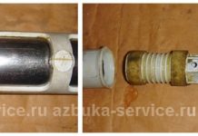
In detail: do-it-yourself repair of a hydraulic cylinder from a real master for the site my.housecope.com.
Basically, hydraulic cylinders are installed on construction and special equipment. Examples of such equipment are trucks with self-dumping bodies (dump trucks), tractors, bulldozers, cranes, etc. Failure of the hydraulic system turns the equipment from a special into a conventional one and makes it practically useless.
Here we will consider the main recommendations related to the repair of hydraulic cylinders with our own hands. I will say right away that this is a rather long and laborious process that will require certain skills from you. Therefore, if you are not confident in your own abilities, seek help from professionals, for example, here - they will help you solve all problems with the hydraulic cylinder and the system as a whole.
In the overwhelming majority of cases, the main failure of the entire hydraulic system is the cylinder rod. Let's talk about him.
First, you have to dismantle the hydraulic cylinder from the car. How to do it - you can find out from the instruction manual for your car. All machines are different, all have their own hydraulic system, so there is no single instruction.
After dismantling the hydraulic cylinder, you need to carry out a visual inspection of the device. The housing must not be damaged in any way and must form a single, sealed structure. If a visual inspection showed nothing, and often this happens, then we proceed to disassemble the hydraulic cylinder itself. In most cases, the problem is hidden inside.
After disassembly, you should receive, roughly speaking, 3 main parts - rod, cylinder and piston. Now it is necessary to conduct a thorough inspection of all 3 parts for damage. The stem must not be bent or bent. Otherwise, it must be replaced. The cylinder should not have significant depletion on the inner walls throughout its entire area. Large grooves or grooves will compromise the tightness of the entire structure. A cylinder with a high output must be either grinded or replaced with a new one.
| Video (click to play). |
The piston must also be free of damage and signs of significant wear. It is best to replace all cuffs and seals with new ones immediately. They are not so expensive, and it will be costly to disassemble the hydraulic cylinder again, so that it will be costly to replace them.
Repair of the hydraulic cylinder for lifting the body gas 3309.
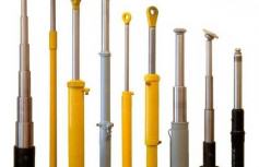

Basically, hydraulic cylinders are installed on construction and special equipment. Examples of such equipment are trucks with self-dumping bodies (dump trucks), tractors, bulldozers, cranes, etc. Failure of the hydraulic system turns the equipment from a special into a conventional one and makes it practically useless.
Here we will consider the main recommendations related to the repair of hydraulic cylinders with our own hands. I will say right away that this is a rather long and laborious process that will require certain skills from you. Therefore, if you are not confident in your own abilities, seek help from professionals, for example, here - they will help you solve all problems with the hydraulic cylinder and the system as a whole.
In the overwhelming majority of cases, the main failure of the entire hydraulic system is the cylinder rod. Let's talk about him.
First, you have to dismantle the hydraulic cylinder from the car. How to do it - you can find out from the instruction manual for your car. All machines are different, all have their own hydraulic system, so there is no single instruction.
After dismantling the hydraulic cylinder, you need to carry out a visual inspection of the device. The housing must not be damaged in any way and must form a single, sealed structure.If a visual inspection showed nothing, and often this happens, then we proceed to disassemble the hydraulic cylinder itself. In most cases, the problem is hidden inside.
After disassembly, you should receive, roughly speaking, 3 main parts - rod, cylinder and piston. Now it is necessary to conduct a thorough inspection of all 3 parts for damage. The stem must not be bent or bent. Otherwise, it must be replaced. The cylinder should not have significant depletion on the inner walls throughout its entire area. Large grooves or grooves will compromise the tightness of the entire structure. A cylinder with a high output must be either grinded or replaced with a new one.
The piston must also be free of damage and signs of significant wear. It is best to replace all cuffs and seals with new ones immediately. They are not so expensive, and it will be costly to disassemble the hydraulic cylinder again, so that it will be costly to replace them.
Dump truck ZIL-MMZ-4502. Hydraulic cylinder
The hydraulic cylinder (Fig. 15) is a telescopic single-acting cylinder with four telescopic links, designed to lift the body.
It consists of a body 21, a bottom b, sliding links 20, ball bearings 2 and 12, cast iron guide inserts (sectors) 19 and 24 and seals.
Sealing of the sliding / links is carried out by means of rubber o-rings 18, installed in the grooves of the body and links.
To increase the reliability of the sealing rings, plastic (fluoroplastic) protective washers 17 are installed in the same grooves.
To prevent dust and dirt from entering the hydraulic cylinder, rubber wipers 16 are installed in its upper part.
The maximum travel of the retractable links when lifting the body is limited by the protrusions in the body, and when lowering - by the protrusions of the links and split thrust rings 25.
The bottom b is screwed onto the body from below, sealed with a rubber O-ring 26.
There is an oil drain hole in the bottom, closed with a plug 27.4
The fastening of the hydraulic cylinder to the brackets of the subframe 1 (Fig. 16) and the body 5 is made in the form of ball joints and is carried out using ball bearings 2, b and ball heads 5, 9 (see Fig. 15) screwed into the retractable link and the bottom, and fixed retaining rings 15 and 23.
To prevent the hydraulic cylinder from rotating around the longitudinal axis, a rocker 9 (see Fig. 16) is attached to the link 7 of the body, which is included in a special groove in the bracket of the lower support of the hydraulic cylinder 1.
The flow of oil into the hydraulic cylinder and drainage are carried out through the hole A in the body of the hydraulic cylinder 21 and the union 22 (see Fig. 15).
The rubbing surfaces of the hydraulic cylinder sprinkling joints are lubricated through the nipples 1 and 13.
Rice. 15. Hydraulic cylinder.
1, 13 - nipples; 2, 12 - spherical dough; 3, 11, 14, 15, 28 - retaining rings; 4 10 - nuts; 5, 9 - ball heads; 6 - bottom; 7 - link for attaching the wings; 8 — plunger head; 16 - wipers; 17 — protective washers; 18 and 26 — O-rings; 19 and 24 — guide inserts (sectors); 20 — pull-out links; 21 — case; 22 — fitting; 23 — cork; 25 — thrust rings (split); 27 — drain plug;
A - hole for supply and drain of oil
Rice. 16. Attachment of the hydraulic cylinder and limiting valve
When disassembling the hydraulic lift cylinder (see Figure 93), unscrew the plug 1 from the bottom of the 37 cylinder, unscrew the bottom 37 of the cylinder with a special key, from the body 26 and remove the thrust ring 32 from the bottom.
Remove the housing 26 assembled with the clamp 30 of the lower support from the third sliding tube 27 of the cylinder, remove the retaining ring 11 from the groove of the pipe, press out the guide 13 of the third sliding tube and remove the washer 14, the sealing ring 15 and the sleeve 16 from the grooves of the guide.
The half rings 31 are removed from the grooves of the third sliding tube 27 of the cylinder, the tube 27 of the cylinder is removed together with the second sliding tube 28 of the cylinder, the retaining ring 8 is removed from the groove of the pipe, the guide 6 of the second sliding tube is pressed out and the washer 17, the sealing ring 18 and bushing 19.
Take out the guide half rings 33 from the grooves of the second sliding tube 28 of the cylinder, remove the retaining ring 5 from the groove of the tube, remove the tube 28 assembled with the first sliding tube 29 of the cylinder.
The guide half rings 35 are removed from the pipe grooves, the pipe locking ring 29 is removed with pliers (Fig. 305), the head 9 (see Figure 93) of the upper cylinder support is pressed out with a puller, the guide 3 of the first sliding pipe 29 is pressed and the washer 21 is removed from the grooves. , O-ring 22 and bushing 24.
The pin is pressed out of the hole in the cylindrical part of the head of the upper cylinder support, the head 9 from the adapter 2 and the nut 10 of the upper cylinder support is removed from the head.
The disassembled parts are thoroughly washed, cleaned and sorted. Before assembly, all assembled parts of the unit must be wiped and blown with dry compressed air.
When assembling the cylinder (see Fig. 93), the ball head 9 of the upper cylinder support is inserted into the hole of the nut 10, which is pressed with a cylindrical surface into the hole of the adapter 2 of the head with a wooden hammer until it stops against the collar. Then a pin is pressed into the hole in the protruding part of the head so that the protruding ends of the pin are of the same length.
The subassembled assembly with the adapter 2 is pressed with a wooden hammer into the bore of the first sliding tube 29 of the cylinder assembly until it stops and with pliers (see Figure 305) insert the locking ring into the groove of the sliding tube of the cylinder.
A thrust ring 25, a bushing 24, a wiper 4, a ring 22 and a washer 21 are installed in the grooves of the guide 3 of the sliding tube of the cylinder.
The assembled guide with O-rings is pressed with a mandrel onto the sliding tube 29 of the cylinder assembly.
Collect the guide 6 of the second sliding tube with a stop ring 23, bushing 19, wiper 7, ring 18 and washer 17. Press the assembled guide with O-rings into the third sliding tube 27 of the cylinder until it stops and insert the retaining ring 8 into the groove of the cylinder tube.
A guide 13 of the third sliding tube 27 of the cylinder is assembled with a thrust ring 20, a bushing 16, a wiper 12, a ring 15 and a washer 14. The assembled guide with rings is pressed into the cylinder body 26 in assembly until it stops and the locking ring is inserted into the pipe groove.
Then, two guide half rings 35 are inserted into the grooves of the first sliding tube 29 of the cylinder, a assembled pipe with a guide and half rings is inserted into the second sliding tube 28, and a locking ring 5 is inserted into the groove of this tube.
In the groove of the second cylinder sliding tube 28, two guide half rings 33 and a third cylinder sliding tube 27 are inserted. Two guide half rings 31 are inserted into the groove of the pipe 27 and the cylinder body 26 is fitted with a clamp 30 of the lower support.
An O-ring 32 is installed in the groove of the bottom, the bottom is screwed onto the stationary pipe of the cylinder with a special key, and plug 1 is screwed into the bottom of the cylinder.
The assembled hydraulic lift cylinder is tested for tightness with industrial oil 12 at a pressure of 15 MPa (150 kgf / cm2) on a stand (Fig. 306). Under the influence of oil pressure, the cylinder links should extend smoothly without jamming. Oil leakage is not allowed.
Hydraulic Cylinder Repair Binotto Film 2
Repair kit for hydraulic cylinder KAMAZ 55111
Repair of hydraulic cylinders - kamaz, video, in St. Petersburg, price, tractor
Cylinder kamaz continued
Body lifting hydraulic cylinder KAMAZ 55111
Hydraulic cylinder ZIL. We disassemble the cylinder zil dump truck. Kamensk-Uralsky. Zil dump truck.
Hydraulic cylinder KAMAZ 55102-8603010 (3-rod), Hydraulic cylinder KamAZ collective farmer
KAMAZ 45143-012-13 body lifting hydraulic cylinder (
Binotto Hydraulic Cylinder Repair
Before starting to describe the principle of operation of such a mechanism as a hydraulic cylinder, you need to have at least a minimum understanding of the use of hydraulics in the automotive industry. As you know, thanks to it, it is possible to significantly increase the efficiency of various works and functions.
ATTENTION! Found a completely simple way to reduce fuel consumption! Don't believe me? An auto mechanic with 15 years of experience also did not believe until he tried it.And now he saves 35,000 rubles a year on gasoline! Read more"
What is a cylinder? It is a mechanism that belongs to a class of devices characterized as reciprocating propulsion systems. It is an essential element of any technique used for construction, submersible or excavation purposes.
Hydraulic cylinders or GCD according to their purpose can be different:
- GCD for lifting the body (GCDP), crane boom, bucket, etc .;
- Hydraulic mechanisms for turning the same boom, bucket, etc .;
- HCD compression, such as doors, hatches.
The main versions of the GCD are shown in the table below.
The most common are, of course, GCDP bodies, which have been used since the beginning of the production of automobile trucks. The dump trucks that first saw the world were initially equipped with chain and cable lifts, but they were too unreliable. Engineers have also tried to develop inertial lifts driven by a load.
Because of this imperfection of the above structures, new research was required. The breakthrough was made in the 1920s by Miller. It was she who patented the hydraulic lifting device of the truck body.
GCDP becomes a standard in the 30s of the last century and is installed on the vast majority of machines with lifts and mechanisms. Since then, there have been no global changes in the design of the GCDP.
The modern GCDP mechanism consists of a subframe, a platform and a hydraulically operated tipping element.
The world's leading truck manufacturers, such as MAZ, BelAZ, Volvo, ZIL, Man and others, produce trucks with unloading back. As for the specific design of the GCDP, it will depend on the type of dumping equipment.
For example, on dump trucks, which work mainly in open pits, a double-acting GCDP, equipped with a return link, is more often installed. The latter softens the impact when unloading large stones and rock fragments. In addition, the return link facilitates convenient platform lowering.
As for conventional dump trucks, so to speak, of a small type, they are equipped with a single-acting gas central control unit, because the angle of the bucket is less than that of mining dump trucks.
As mentioned above, GDCUs can be different. In other words, the movable link of the hydraulic cylinder can be either a rod or a liner. GCDP piston, translational, plunger, etc. - these are mechanisms of a serial type, but today non-standard types of these engines are also known (they are usually made to order).
The main links of any type of GCDP are the following elements.
- The stem of a custom-made GCDP, depending on the specific operating conditions, can be chrome-plated.
- As for the seals and cuffs, the mechanism uses, as a rule, polyurethane seals with protection, effectively sealing the GCDP operating in difficult conditions with an OP speed of no more than 0.5 m / s (at a pressure of up to 63 MPa).
- Inside the mechanism, there are also guide rings made of very durable antifriction material.
- An equally important link of the GCDP is the working pressure, on which the dynamics and speed of work directly depend.
In order for the choice of a lifting type hydraulic cylinder to be carried out correctly, you should rely on these points:
- Focus on the main technical indicator - the level of nominal pressure;
- It is also impossible to ignore the indicators of maximum and peak pressure;
- It is also necessary to pay attention to the scope of the mechanism;
- Consideration should be given to workloads and operating conditions.
Additional indicators are no less important: service life, work safety, operating costs and much more.
It is to them that experts recommend paying attention in the first place. The duration of the work of the GCDP will depend on the seals.
So, here are the obligations for the cuffs:
- They must first of all be tight enough to create a minimum level of friction;
- Small in size;
- Be compatible with the working fluid;
- It is better that the cuffs are rubber and round (in extreme cases, rubber-fabric seals can be used);
- It is necessary to install the cuffs with protective rings made of fluoroplastic, so that the latter prevent the cuffs from being squeezed out of the seating grooves due to high pressure;
- The presence of a rod wiper is required in the MCD;
- In some cases, double-acting seals are recommended for use, containing a rubber-fabric ring with shaped additions on the sides.
The above-described seals are considered a whole system, a sealing unit. It is placed in a geometrically simple groove with not tight tolerances.
Hydraulic cylinders or hydraulic cylinders in our country have been produced throughout history not only by specialized enterprises, but also by private factories of hydraulic equipment. The only difference was that specialized enterprises produced cylinders for special-purpose equipment (tractors, shaft supports, universal machines), and factories - for their machines. In fact, the factories were deprived of the opportunity for progress and improvement, since they additionally loaded their own production, diverting specialists and finances from solving the most important tasks.
As for today, we can openly state that the situation has changed radically. Plants such as MAZ, Kamaz, etc., have now significantly reduced the production of hydraulic cylinders, preferring to order them from outside. In turn, this made it possible for a number of Russian enterprises engaged in the production of such units to radically revise the nomenclature in order to improve the quality.
What determines the quality, reliability and durability of hydraulic cylinders? Of course, these are several points. First of all, this concerns the modern design of the product. Equally important is the unification of elements, materials and components, as well as the processing technology of parts, the availability of appropriate equipment, etc.
As a result, such large car factories as Kamaz, MAZ do the following. They buy hydraulic cylinders from outside, thus getting permanently perfect products made by specialist firms.
Check out the table for approximate prices for various body lift cylinders from Gidromash.


Complete repair and installation of hydraulic cylinders on GAZ 53. Our channel:
Body support GAZ dump truck (malfunction repair)
The rear supports of the GAZ dump truck body eventually need to be repaired so that the body does not "walk"
Hydraulic cylinder ZIL. We disassemble the cylinder zil dump truck. Kamensk-Uralsky. Zil dump truck.
Hydraulic cylinder GAZ 53 3-rod
Repair of the hydraulic cylinder for lifting the body KamAZ 55-11. Transformation of the tractor into a dump truck.
Hydraulic cylinder GAZ-53 4-rod
Do-it-yourself gas 53 hydraulic cylinder repair
Repair of the hydraulic cylinder for lifting the body gas 3309.
Body lift limiting valve. Principle of operation. Repair. Service.
Hydraulic cylinder ZIL 5-rod (with platforms)
Hydraulic cylinders disassembly assembly repair kit.
tractor MTZ 80. repair of a hydraulic cylinder
Repair of the Kamaz Hydraulic cylinder. Lift Kamaz.
Hydraulic cylinder for ZIL 4546.
The body is falling in neutral, GAZ 53 dump truck repair!
This needs to be crammed into a gazelle
In this video you can see the main stages of hydraulic cylinder repair. From the moment of acceptance to the final test of the repaired product. We will also tell you about the main reasons for the failure of the hydraulic cylinder and our recommendations for initial repair. See the second part here More details can be found on the website
Repair of the hydraulic cylinder for lifting the body gaz 3309
Disassembly, assembly, principle of operation, possible breakdowns of the valve for limiting body lift ZIL, KamAZ.
Hydraulic cylinder ZIL 5-rod (with platforms) Hydraulic cylinder for lifting the body ZIL 5-rod: 1.The nominal pressure is 100 kgf / cm. 2. The maximum pressure is 160 kgf / cm. 3. Rod diameters - 55; 73; 92; 111; 134 mm. 4. Stroke of the 1st stage - 225 mm. 5. The stroke of the 2nd stage is 211 mm. 6. Stroke of the 3rd stage - 224 mm. 7. The stroke of the 4th stage is 232 mm. 8. The stroke of the 5th stage is 208 mm. 9. Center-to-center distance - 488 mm. 10. The total stroke is 1100 mm. 11. Carrying capacity - 6 tons. 12. Weight - 46 kg. Telescopic and piston hydraulic cylinders, hydraulic cylinders for tractor trailers, hydraulic cylinders for trucks and dump trucks, hydraulic cylinders for press, hydraulic jacks. PE ”RODONIT 2008” - production, repair and sale of hydraulic cylinders for trucks.
We are not professional installers and super repairmen. We do it for our equipment. and with the hack to remake us. So do not scold something much. We do it as needed. We handed it over for repairs earlier. there was a lot of hack and it was expensive.
tel / mob +38 098 157-57-98 fax machine +38 067 483-60-94 Selling hydrocylindr Hydrocylindri for Gas, Kamaz, Presa, prip KUN, Hydrocylindri TsS, Hydrocylindri Carpathian in explicitly 500 positions. If you are connected to the hydraulic cylinder, please call and we will act on the Central Hydrocylindr - the process of adjusting the hydraulic power of the pump into the mechanical progressive energy of the cylinder stem. Given the possession of a stagnation in hydraulic installations and systems, the number of problems in one of the most important service services in the company is highly professional and high-quality repair of hydraulic pistons in the middle of the wide range of geometries. Diameter of the stem is 6-400 mm. Hіd 50-9000 mm. Working vice 10-1500.
Removal, repair of the cylinder, installation on the MTZ 80 old cabin. Subscribe, the channel is just developing. There will be many more videos.
Replacing the cuffs in the KamAZ hydraulic cylinder.
Replacing the cuffs in the cylinder of the KAMAZ lift.
In this video I show you how to repair a KAMAZ lift from a to z.
Starting a cold engine in winter is always a problem.
In this video, I show how homemade hydraulic cranes are made. This will help to avoid unnecessary costs and increase the capacity of the hydraulic system.
Do you have your own loader crane? We have a job for you. Rent of manipulators, services of carriers in Russia The driver of the manipulator crane bent the hydraulic cylinder rod when unloading a heavy load. Why did this happen? The more the rod extends outward, the less the symmetry between the rod and the hydraulic cylinder. Especially - this applies to old, not serviced equipment because the oil seals and cuffs are worn out, which causes backlash and idle bypass inside the cylinder.
Dismantling of an arrow, tselindra of the Autocrane KS-3575a
In short, the thing is, all the clutch and gearbox will move somewhere in the summer, there is everything on the clutch, but for now we are doing everything on budget and leave it as it is! The client's desire and all that)))
CONVERSION GAS 3309 RV to Dump Truck Music Ento - Without You Ft. Aimi D [OUT NOW] - Slyde Records
Repair of the Kamaz Hydraulic cylinder. Lift Kamaz.
Overhaul of the hydraulic cylinder KamAZ (elevator) 55-11. Kamaz project # 2.
Do-it-yourself KamAZ hydraulic cylinder repair.
Repair of the hydraulic cylinder KamAZ55111
Hydraulic cylinder KAMAZ 55102-8603010 (3-rod), Hydraulic cylinder KamAZ collective farmer
Hydraulic cylinder ZIL. We disassemble the cylinder zil dump truck. Kamensk-Uralsky. Zil dump truck.
Assembling hydro celindra kamaz
Repair of hydraulic cylinders - kamaz, video, in St. Petersburg, price, tractor
Repair and video about repairing a KamAZ hydraulic cylinder with your own hands video - see here. Car repair at home using video tutorials. We know how to restore a car with minimal investment. Video instruction on auto repair.
Category: DIY car repair
Laughter in the subject: Found a collection of riddles. I read it ... I would never have thought that "That which DALPS during the day and STARTS at night is a hook on the gate" ...
Posted by Admin: at the request of Gerontiy
Car owner reviews: The car is made for Russian roads.
How to repair a hydraulic cylinder with your own hands?
For repairs, it is necessary to disassemble the hydraulic cylinder and properly defect all the parts. So, when disassembling, you should get at least three components of the unit:
The cylinder is defect for damage on the inner wall where the piston with cuffs runs.
The stem is defect in the presence of curvatures.
The piston is defective for damage to the piston itself and cuffs.
If a cylinder, piston or rod is damaged, then it can be replaced, now it is not difficult, in any region you can find a company that will sell components.
As for the cuffs, you can not only buy them in the original, but also pick them up according to the sample.
It is generally easier to make and warrant a new cylinder than to repair an old one.
To repair the hydraulic cylinder, you first need to prepare the workplace, freeing it from all that is superfluous. Before the hydraulic cylinder is dismantled, it is necessary to shut off the machine or unit, and then dismantle the hydraulic cylinder using tools. Next, you can proceed to disconnect the supply hoses from the distributor. Further, the removed hydraulic cylinder with the help of tools at a prepared place can be disassembled and worn out cuffs can be replaced, and then assembled back in the prescribed manner. Next, mount it in place, connect the supply hoses, and, if necessary, change or add oil to the hydraulic system of the unit.
It depends on what kind of hydraulic cylinder. Among the reasons are: Leaks in the cups, curvature of the stem, wear of stationary seals. Sometimes the rod cannot be removed from the liner if the cylinder is large, in such cases it is otherwise very carefully squeezed out by pressure after removing the hydraulic cylinder cover. But this method is very dangerous, since the stock can fly away by several tens of meters. When disassembling, it is imperative to change all seals, otherwise it will flow over again.
The best news for the query "do-it-yourself repair of the hydraulic cylinder zil 130" - click. How to repair a car with your own hands at home. We will help ourselves to repair and repair the car ourselves. We know how to restore a car with minimal investment. I attach a video instruction.
Category: DIY car repair
Laughter in the subject: The son is interested in his mother: - Mom, what do we have for dinner today? - Today we have for dinner, son, there will be one wonderful Georgian dish - they chewed!
Posted by Admin: at Tavus's request
Reviews of the owner of the car: The engine is one hundred percent million. Iron (not counting the rear arches), ideally. Front seats (ELECTRIC Pneumatic mechanical), MUSIC, SOFT RUNNING,
Overhaul of the hydraulic cylinder KamAZ (elevator) 55-11. Kamaz project # 2.
Repair of the hydraulic cylinder KamAZ55111
Repair of the Kamaz Hydraulic cylinder. Lift Kamaz.
Repair of the hydraulic cylinder for lifting the body KamAZ 55-11. Transformation of the tractor into a dump truck.
Do-it-yourself KamAZ hydraulic cylinder repair.
Repair kit for hydraulic cylinder KAMAZ 55111 (full)
KAMAZ 45143-012-13 body lifting hydraulic cylinder (
Hydraulic cylinder ZIL. We disassemble the cylinder zil dump truck. Kamensk-Uralsky. Zil dump truck.
Dump truck KamAZ 55111 lifting the body
Overhaul of the hydraulic cylinder KamAZ (elevator) 55-11. Kamaz project # 2.
Repair of the Kamaz Hydraulic cylinder. Lift Kamaz.
Do-it-yourself KamAZ hydraulic cylinder repair.
Hydraulic cylinder KAMAZ 55102-8603010 (3-rod), Hydraulic cylinder KamAZ collective farmer
Repair of the hydraulic cylinder KamAZ55111
Hydraulic Cylinder Repair Binotto Film 2
Hydraulic cylinder ZIL. We disassemble the cylinder zil dump truck. Kamensk-Uralsky. Zil dump truck.
Repair of the hydraulic cylinder for lifting the body KamAZ 55-11. Transformation of the tractor into a dump truck.
Do-it-yourself KamAZ hydraulic cylinder repair.
Repair of the Kamaz Hydraulic cylinder. Lift Kamaz.
Overhaul of the hydraulic cylinder KamAZ (elevator) 55-11. Kamaz project # 2.
Repair of the hydraulic cylinder KamAZ55111
Repair of hydraulic cylinders. Main stages. Recommendations for the operation of hydraulic cylinders
Repair of hydraulic cylinders - kamaz, video, in St. Petersburg, price, tractor
Hydraulic cylinder KAMAZ 55102-8603010 (3-rod), Hydraulic cylinder KamAZ collective farmer
Hydraulic cylinder ZIL. We disassemble the cylinder zil dump truck. Kamensk-Uralsky. Zil dump truck.
How to repair a hydraulic cylinder with your own hands?
For repairs, it is necessary to disassemble the hydraulic cylinder and properly defect all the parts. So, when disassembling, you should get at least three components of the unit:
The cylinder is defect for damage on the inner wall where the piston with cuffs runs.
The stem is defect in the presence of curvatures.
The piston is defective for damage to the piston itself and cuffs.
If a cylinder, piston or rod is damaged, then it can be replaced, now it is not difficult, in any region you can find a company that will sell components.
As for the cuffs, you can not only buy them in the original, but also pick them up according to the sample.
It is generally easier to make and warrant a new cylinder than to repair an old one.
To repair the hydraulic cylinder, you first need to prepare the workplace, freeing it from all that is superfluous. Before the hydraulic cylinder is dismantled, it is necessary to shut off the machine or unit, and then dismantle the hydraulic cylinder using tools. Next, you can proceed to disconnect the supply hoses from the distributor. Further, the removed hydraulic cylinder with the help of tools at a prepared place can be disassembled and worn out cuffs can be replaced, and then assembled back in the prescribed manner. Next, mount it in place, connect the supply hoses, and, if necessary, change or add oil to the hydraulic system of the unit.
It depends on what kind of hydraulic cylinder. Among the reasons are: Leaks in the cups, curvature of the stem, wear of stationary seals. Sometimes the rod cannot be removed from the liner if the cylinder is large, in such cases it is otherwise very carefully squeezed out by pressure after removing the hydraulic cylinder cover. But this method is very dangerous, since the stock can fly away by several tens of meters. When disassembling, it is imperative to change all seals, otherwise it will flow over again.
Do-it-yourself KamAZ hydraulic cylinder repair.
Repair of the hydraulic cylinder KamAZ55111
Overhaul of the hydraulic cylinder KamAZ (elevator) 55-11. Kamaz project # 2.
Repair of the Kamaz Hydraulic cylinder. Lift Kamaz.
Repair of the hydraulic cylinder for lifting the body KamAZ 55-11. Transformation of the tractor into a dump truck.
Repair of hydraulic cylinders. Main stages. Recommendations for the operation of hydraulic cylinders
Hydraulic cylinder repair, assembly of bridges. Kamaz project # 3.
Hydraulic cylinder ZIL. We disassemble the cylinder zil dump truck. Kamensk-Uralsky. Zil dump truck.
| Video (click to play). |

