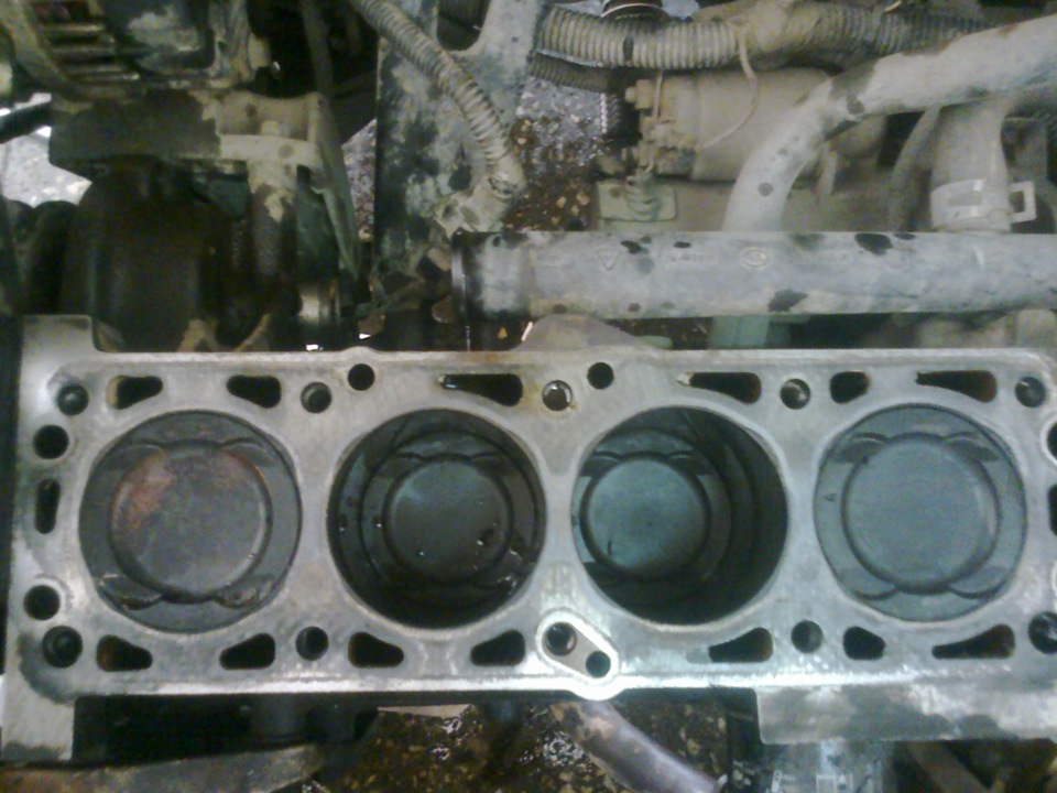
In detail: do-it-yourself repair of the cylinder head of a Daewoo Nexia 16 valves from a real master for the site my.housecope.com.
The order of tightening the cylinder head bolts
Cylinder block gasket marks
Removal and installation of the cylinder head is carried out on a cold engine. The exhaust manifold cannot be removed. The cylinder head can be removed and installed without removing the engine.
Features of removal and installation of the cylinder head of a diesel engine are given in subsection 2.6.1.2.
Defective cylinder head gaskets can be determined by the following features:
- power loss;
- coolant leak. White clouds of exhaust gas when the engine is warm;
- oil leak;
- coolant in engine oil. The oil level does not decrease, but increases. Engine oil gray, foam bubbles on the oil level gauge, liquid oil;
- engine oil in the coolant;
- the coolant boils violently;
- there is no compression in two adjacent cylinders.
Good afternoon, please tell me how much is the chrome plating of the valves now there is the same head with a mileage of 300 thousand and a large backlash of the valves I checked the valve stem the same trouble
Zhen, and on Solaris never "studied" the head?
I had 16 cells. Nexia, 1.5, and so on the highway when I was driving faster than 120-140 km / h ... the consumption was slightly less than when I was driving 100-110 ... this is such a paradox, I think the cylinder head is the same by design
You were probably in 5th gear?
You were probably in 5th gear?
not always, of course, I was just in a hurry and pressed on the trigger ... and the more I pressed on the trigger (well, up to 140 km / h), the less she ate, and when 110-120 trudged ... the consumption per liter was greater (well, very approximately)
| Video (click to play). |
And you try to go to the 4th 100 - 110, the consumption will also not be very large
well, I turn on the 5th only at a speed of over 100 km / h, because before it makes no sense to turn it on
And you try to go to the 4th 100 - 110, the consumption will also not be very large
16 cl. there was the main pair 4.1, and on the 8th class. now it is 3.9, and 16 cl. up to 3500 rpm was just dead
Thank you very much for the information, I watched a lot of your videos, very informative and interesting.
I had a question, capital for a Subaru engine, ej204, you had one somewhere, but I'm capital for an earlier version, 2000, of course the quality was different, but that's not the question.
Looking at the manual, I see the following data:
Guide bush inner diameter
valve: 6,000 - 6,012 mm
Valve stem outer diameters:
Intake 5.955 - 5.970 mm
Exhaust 5.945 - 5.960 mm
In the worst case, with a guide of 6.01 and even if the intake valve is 5.96, we have 0.05mm, and in the exhaust one 0.06mm, and this is a tolerance. What to do if the parameters are within tolerances, to collect the motor, or how is it necessary to achieve a reduction in this data, and again what data should be? After all, the manufacturer gives such tolerances. Thanks!
such parameters are a guarantee against hanging valves, if you suddenly fill in fired oil or fired gasoline, this is a reinsurance for the manufacturer, this has already been done on the Lacetti
It turns out that 5-6 acres is a necessary tolerance? Today I measured my heads and valves, and it turns out, 4-6 acres. But the engine was in excellent condition, there were no broken seats or anything else, all the valves were ground in place, the engine passed from 90 to 120.
Thank you very much for the information, I watched a lot of your videos, very informative and interesting.
I had a question, capital for a Subaru engine, ej204, you had one somewhere, but I'm capital for an earlier version, 2000, of course the quality was different, but that's not the question.
Looking at the manual, I see the following data:
Guide bush inner diameter
valve: 6,000 - 6,012 mm
Valve stem outer diameters:
Intake 5.955 - 5.970 mm
Exhaust 5.945 - 5.960 mm
In the worst case, with a guide of 6.01 and even if the intake valve is 5.96, we have 0.05mm, and in the exhaust one 0.06mm, and this is a tolerance. What to do if the parameters are within tolerances, to collect the motor, or how is it necessary to achieve a reduction in this data, and again what data should be? After all, the manufacturer gives such tolerances. Thanks!
Unfortunately, they now do everything with the maximum tolerance. This affects the resource, that is, the larger the initial clearance, the less the total mileage will be.
Good day. Did you get engines from Italian cars for inspection such as Lancia Thema 2.0 Turbo gasoline Lancia Kappa or Alfa Romeo?
Only such a head
Thank you very much for the information, I watched a lot of your videos, very informative and interesting.
I had a question, capital for a Subaru engine, ej204, you had one somewhere, but I'm capital for an earlier version, 2000, of course the quality was different, but that's not the question.
Looking at the manual, I see the following data:
Guide bush inner diameter
valve: 6,000 - 6,012 mm
Valve stem outer diameters:
Intake 5.955 - 5.970 mm
Exhaust 5.945 - 5.960 mm
In the worst case, with a guide of 6.01 and even if the intake valve is 5.96, we have 0.05mm, and in the exhaust one 0.06mm, and this is a tolerance. What to do if the parameters are within tolerances, to collect the motor, or how is it necessary to achieve a reduction in this data, and again what data should be? After all, the manufacturer gives such tolerances. Thanks!
By the way, in general, there should be 2 hundred parts inlet and 3 hundred parts out, the internal Japanese engines did this, here the head passed 300 thousand km, and the gap increased by only 0.005 mm and the setting there was 2 and 3 hundred parts.
"DAEWOO NEXIA from 1994 to 2008. release with engines 1.5 SOHC (G15MF), 1.5 DOHC (A15MF) and 1.6 DOHC (F16D3). Operation, maintenance and repair manual with step-by-step descriptions of operations and color photo illustrations.
To replace the gasket, it is advisable to remove the cylinder head assembly with the timing belt, with the exhaust manifold and the intake manifold.
1. We prepare the car for the job.
2. We drain the engine oil and coolant.
3. Remove the rear timing belt cover.
4. Finally, we unscrew the upper generator mounting bolt.
5. We remove high-voltage wires.
6. Disconnect the wiring harness pads from the idle speed sensor, throttle position sensor, camshaft position sensor, coolant temperature gauge sensor, EGR valve, fuel injectors, coolant temperature sensor, ignition coils and move the wiring harness back.
7. Disconnect the block of the wiring harness of the control oxygen concentration sensor.
8. Key by 12 mm unscrew the nut that secures the tip of the "ground" wires to the cylinder head.
9. Disconnect the three vacuum tubes from the intake manifold.
Warning!
When disconnecting, label the tubes in any way you can to ensure they are connected correctly during reassembly.
10. Key by 17 mm we hold the union from turning, and with the key by 19 mm unscrew the tip of the brake booster hose from the intake manifold.
11. Disconnect from the throttle assembly and move the throttle cable to the side.
12. Disconnect the fuel lines from the fuel rail.
13. Using the pliers, we loosen the clamp and disconnect the heater radiator hose from the tee of the cooling system.
14. Key by 12 mm we unscrew the two upper bolts of the intake manifold bracket.
15. Key by 14 mm we unscrew the lower bolt of the intake manifold bracket and remove the bracket.
16. Disconnect the main catalytic converter from the exhaust manifold.
17. Remove the cylinder head cover
18. Using the pliers, we loosen the tightening of the clamp and disconnect the cooling system hose from the thermostat cover.
19. We cut the clamp and disconnect the hose of the crankcase ventilation system (a new clamp will be needed during assembly).
20. Key by 13 mm we unscrew the ten bolts securing the cylinder head in the indicated order.
21. Separate from the cylinder head and remove the camshaft housing assembly with the ignition module and the camshaft position sensor.
Steps 22, 23 and 24 are not necessary to replace the cylinder head gasket; the head assembly can be removed.
22. We remove the rockers of the valves and lay them out in such a way that during assembly they are installed on
former places.
23. We remove the hydraulic lifters from the wells. If old hydraulic compensators are installed, then we lay them out in such a way that during assembly
install in the same places.
24. We remove the thrust washers of the rockers and lay them out in such a way that they can be installed in their original places during assembly.
25. Remove the cylinder head assembly with the intake manifold, exhaust manifold, throttle assembly and elements of the engine control system.
Recommendation
The operation is best done with an assistant.
Recommendation
Cover the catalytic converter with any suitable material to prevent foreign matter from entering the catalytic converter.
26. Remove the cylinder head gasket (if necessary, separate it from the cylinder block using a sharpened knife).
27. We clean the mating surfaces of the cylinder block and the block head, as well as the bolts of the block head and their fastening holes.
Warning!
Make sure that dirt does not get into the oil channels, the jacket of the cooling system and the engine cylinders.
28. We carefully inspect the mating surfaces of the block head and cylinder block for damage, especially in the place of damage to the head gasket.
29. Install a new head gasket.
30. We clean the mating surface of the camshaft bearing housing ...
... and the cylinder head.
31. We apply a flange sealant designed for cars with oxygen concentration sensors on the seating surface of the camshaft housing.
32. We install the block head and the camshaft bearing housing.
Tighten the bolts of their fastening with a torque 25 Nm in the specified sequence.
33. In the same sequence, we turn the cylinder head bolts to an angle of 70 °,
and then at an angle of 30 °.
34. If removed, install hydraulic lifters, rocker thrust washers and rockers themselves in their original places.
Recommendation
Before installing new hydraulic lifters, immerse the hydraulic lifter in a container with fresh engine oil. Press the compensator valve several times until air bubbles stop escaping to fill its internal cavity with oil.
35. Install the rest of the parts in reverse order.
Before starting work on replacing the cylinder head gasket, it is necessary to drain the oil and coolant from the engine, remove the BB wires. Remove the timing belt protective cover and completely unscrew the upper alternator mounting bolt.
- throttle position sensor
- camshaft position sensor
- coolant temperature sensor
- coolant temperature gauge sensor
- oxygen concentration sensor
- idle speed regulator
- EGR valve
- fuel injectors
- ignition coils
Using the keys to “17” and to “19”, unscrew the hose fitting that goes to the vacuum brake booster.
Disconnect the throttle cable from the throttle. Disconnect the fuel lines from the fuel rail
... and the intake manifold bracket lower mounting bolt.
Disconnect the main catalyst from the exhaust manifold.
Remove the cylinder head cover
We unscrew ten bolts of fastening of the cylinder head in the indicated sequence with a key on “13”.
We separate it from the cylinder head and remove the camshaft housing assembly with the ignition module and the camshaft position sensor.
Remove the cylinder head assembly with the intake manifold, exhaust manifold and throttle. To prevent foreign objects from getting into the catalyst, it is advisable to cover it with a piece of cloth.
Remove the old cylinder head gasket. We clean the head of the block and the cylinder block from the gasket, if necessary, if the gasket has become attached, we clean it with a knife to the metal. Perform this operation carefully so that dirt does not get inside the engine.
We inspect the mating surfaces of the cylinder head and cylinder block for damage, especially in the place of damage to the cylinder head gasket.
Installing a new gasket
Install the cylinder head and the camshaft bearing housing by tightening the mounting bolts in the specified sequence to a torque of 25 Nm. In the same sequence, we turn the cylinder head mounting bolts at an angle of 70 degrees, and then at an angle of 30 degrees.
We install the rest of the removal of the part, we connect the sensor connectors
The K-POWER Workshop received a cylinder head (cylinder head) from a Daewoo Nexia 1.5 SOHC car for repairs (one camshaft, 2 valves per cylinder). Machine '98, engine mileage 310 thousand km The machine is operated on gas in Nizhnekamsk and Naberezhnye Chelny. The cylinder block is capitalized by the forces of the car owner, and our range of responsibilities is to carry out a high-quality head repair.
Let's look at the “patient”. The exhaust and inlet channels are located on different sides of the head axis, each valve has 1 spring, the camshaft is in a removable housing (like on the VAZ classic), the valve is driven by rockers, there are hydraulic supports. The head leaves a pleasant impression - it is competently and beautifully designed (this engine has a German engine from the Opel Cadet in its roots).
We dry out the valves, inspect and defect parts. The owner of the car has already repaired the head, or rather, just rubbed the valve. As a result, we observe a huge working chamfer in width. The valves in the guide bushings are very loose - the bushings need to be replaced.
The rocker (valve lever) for 310 thousand km has acquired a noticeable wear hole on the working part, so the levers should be replaced. The valves have a stem of 7 mm, we observe strong seizures and nicks on the stems - they were clearly damaged when the valves were rubbed in. The valve is also under replacement.
Ordered spare parts for repair:
1) Valves inlet and outlet - 4 + 4 pieces
2) Valve sleeve guides GM - 8 pcs
3) Levers (rocker arms) valves FEBI 8 pcs
4) Oil scraper seals VR - 8 pcs
5) Hydraulic lifters (supports) QML - 8 pcs
6) Tablets-supports for levers GM - 8 pcs
Surprisingly, spare parts for this cylinder head are very cheap and a full set of spare parts for repair cost a little more than 5 thousand rubles.
Daewoo Nexia 1.5 SOHC cylinder head valve bushings are made of pearlitic cast iron, original GM bushings are quite cheap. Unlike the unsuccessful Opel Vectra cylinder head, these bushings have a lock groove that prevents the cap from sliding off the bushing. The bushings have different heights of protrusion from the cylinder head and it is important to maintain these dimensions when repressing the bushings. We were also faced with the fact that the new bushings have an inner diameter of 6.40 mm - and it is possible to turn them qualitatively without loss of alignment only on the machine. We unrolled the bushings on a CNC machine.
It is interesting that the combustion chamber has an excellent shape - if the cylinder head was refined, then, in general, there is nothing to refine the combustion chamber.
Daewoo Nexia 2008. REMOVING THE CAMSHAFT AND PUSHERS OF THE F16D3 ENGINE VALVES
We carry out work to replace failed camshafts (wear of camshafts, seizure of the shaft journals) or valve pushers (loss of performance), as well as when replacing valve stem seals and repairing the cylinder head.We perform operations to identify a faulty hydraulic pusher after a short period of time (15-20 minutes) after stopping the engine.
Remove the cylinder head cover (see "Replacing the cylinder head cover gasket", page 77).
To check the serviceability of the hydraulic pusher.
... press on it with a screwdriver, trying to press the pusher into the socket of the cylinder head (while the corresponding cam of the camshaft must face the pusher with its "back", ie do not press on it).
In this case, a serviceable hydraulic pusher will move in the cylinder head socket with significant effort, compressing the valve spring. If, with a little effort, the hydraulic pusher itself is squeezed, it must be replaced. To do this, remove the camshaft pulley a (see "Replacing the camshaft oil seal", p. 77).
Using the "10" head, evenly, in several steps (half a turn per pass), unscrew two bolts of each of the five camshaft bearing caps.
Remove the camshaft bearing caps.
The first (far right) cover is different from the other covers.
We take out the exhaust camshaft from the beds of the cylinder head.
If necessary, dismantle the intake camshaft in the same way.
We take out the hydraulic pusher from the socket in the cylinder head.
Before installing, we lower the new hydraulic pusher into a container with clean engine oil and press the plunger pair of the hydraulic pusher several times until air bubbles stop escaping from the hole in its groove.
Install the hydraulic pusher in reverse order. Other hydraulic pushers are replaced in the same way. Before laying the camshaft in the bed of the cylinder head, apply a thin layer of engine oil to the bearing journals and cams of the shaft.
Having laid the shaft, we install the shaft bearing caps in accordance with the order of their designation in the cylinder head and the markings on the outer surface of the caps.
The order of designation of covers in the cylinder head
Cleaning the valve guides
Checking the flatness of the cylinder head contact surface
Measuring the height of the cylinder head
The need to remove the cylinder head can arise for several reasons. One of these reasons is the replacement of the head gasket due to its “breakdown”, as a result of which the coolant from the cooling system enters the engine cylinders. It is not difficult to determine this malfunction - the level of the coolant in the expansion tank decreases, and there are no noticeable leaks at the joints of the hoses and pipes of the cooling system, the oil pressure in the lubrication system drops, the exhaust gases escaping from the muffler acquire a characteristic white color.
When replacing the cylinder head gasket, complete disassembly of the head itself, as well as removing the intake and exhaust manifolds from it, is not required.
Difficulty: 4.
Lead time: 8 hours.
Withdrawal:
1. We install the vehicle securely on a viewing pit or overpass (see “Standard Operations”).
2. Remove the pressure in the fuel system. To do this, with the ignition off, remove the fuse F7 from the fuse box, start the engine and leave it running until it stops. Then turn off the ignition.
3. Disconnect the cable from the negative terminal of the storage battery (see “Standard Operations”).
4. Drain the coolant from the radiator (see “Replacing the coolant”).
5.Remove the timing belt and the rear timing cover (see "Rear timing cover - removal and installation").
6. Disconnect the front pipe of the exhaust system from the exhaust manifold of the engine. To do this, use a 14 socket wrench to unscrew 2 bolts (on the A15MF engine - 3 bolts) of the intake pipe fastening (see "Engine oil pan - removal and installation" p. 5).
7. Using a large slotted screwdriver, remove the tip of the vacuum hose from the amplifier housing.
8. Remove the throttle cable.
9. Disconnect the fuel line from the fuel rail on both sides.
10. Pressing on the metal latches, disconnect the electrical connectors from the injectors.
11. Disconnect the 2 electrical connectors from the ignition distributor.
12. Using a 12 spanner spanner, unscrew the nut of the ignition distributor bracket and remove the ignition distributor.
13. Disconnect the electrical connector from the coolant temperature sensor.
14. Disconnect the electrical connectors from the idle speed controller and throttle position sensor.
15. Unscrew the bolt securing the negative wires from the camshaft bearing housing and disconnect the wires.
16. We transfer the wiring harness with all connectors behind the intake manifold of the engine.
17. Disconnect the coolant temperature gauge sensor connector (pos. 1). Using pliers, squeeze the clamp and disconnect the engine cooling hose (item 2) from the cylinder head. Using a 12 spanner spanner, unscrew the bolt securing the tension adjustment bar for the alternator drive belt (item 3) and remove the bar.
18. Using pliers, squeeze the clamp and disconnect the hose from the cylinder head that connects the upper radiator reservoir with the thermostat housing pipe.
19. Disconnect the throttle body heating hoses.
20. Having loosened the clamp, disconnect the hose of the gas evacuation system from the line.
21. Using a 13 socket wrench with a ratchet, unscrew 10 bolts securing the cylinder head.
22.. and remove the cylinder head together with the camshaft, intake and exhaust manifolds.
23. Remove the cylinder head gasket, thoroughly clean the mating surfaces of the head and cylinder block, install a new gasket.
If there are deepened grooves on the mating surfaces of the cylinder head or cylinder block, left by coolant that pierced the gasket, then the head or cylinder block should be replaced or sent to a specialized workshop for milling.
We install the cylinder head in the reverse order. Tightening the cylinder head bolts should be done from the center to the edges of the head. The bolts are pre-tightened to a torque of 25 Nm. Then the bolts are tightened to a torque of 100 Nm. After that, each of the bolts is rotated sequentially by 60 degrees, then another 60 degrees, and then another 30.
Daewoo Nexia cylinder block
This article on replacing the cylinder head gasket is suitable for Daewoo Nexia cars of all years of production with engine variations 1.5 DOHC, 1.6 DOHC, 1.5 SOHC.
To replace the cylinder head gasket, it is wiser to remove the cylinder head along with the timing, intake pipes and exhaust manifold.
Detailed instructions for performing this operation:
Such a procedure is a matter that requires increased attention, patience and certain skills. Of course, it is best of all, in case of such breakdowns, to drive the car to a service station, where the mechanics will skillfully and quickly complete the specified task.
replacement gaskets cylinder head on nexia 16 valves
DAEWOO NEXIA from 1994 to 2008 Release P with engines P1,5 SOHC (G15MF), 1.5 DOHC (A15MF) and 1.6 DOHC (F16D3).
Operation, maintenance and repair department with step-by-step descriptions of operations and color photo illustrations. Head cylinder block. Replacement gaskets... To replace gaskets it is advisable to remove the head cylinder block complete with timing, with exhaust manifold and intake manifold.Replacing the timing belt on the Priora 16 valves - photo and. Sequence of execution 1. Prepare the car for work.
2. Drain the engine oil and coolant. 3. Remove the rear timing belt cover. 4. Finally, unscrew the upper bolt of the generator mounting.
5. Replacing the timing belt Daewoo Nexia DOHC 16 valves p. VAZ 2110 engines 8 and 16 valves replacement of the alternator belt of the VAZ 2110 alternator. Remove the high-voltage wires. 6. Disconnect the wiring harness pads from the idle speed sensor, throttle position sensor, camshaft position sensor, coolant temperature gauge sensor, EGR valve, fuel injectors, coolant temperature sensor, ignition coils and move the wiring harness back.
7. Disconnect the block of the wiring harness of the control oxygen concentration sensor. 8. Using a 12 mm wrench, unscrew the nut that secures the tip of the ground wires to the head cylinder block.
9. Disconnect the three vacuum tubes from the intake manifold. 10. Use a 17 mm wrench to keep the fitting from turning, and with a 19 mm wrench, unscrew the brake booster hose tip from the intake manifold.
11. Disconnect from the throttle assembly and move the throttle cable to the side. 12. Disconnect the fuel lines from the fuel rail. thirteen.


