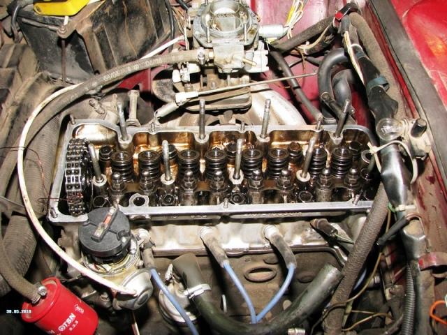
In detail: DIY repair of the cylinder head of a VAZ 2105 from a real master for the site my.housecope.com.
Lectures on the topic "Theory of internal combustion engines"
No, you don't need to make such a collector. For the receiver in more detail in the video "Intake systems"
damn guys, you are doing a good job, I can only dream (
Okovsky collectors look like two frightened monkeys :)))
how many watts is it powerful? and turns, more precisely, please
i dont understand a thing your saying 😛 but i enjoyed it anny way
Eugene, but you can order in your city such 2 inlet pipes from the "eye" in our city there are no such spare parts I tried to find on the Internet, I did not find it, I have long wanted to do something similar on my car mail for contact
Nazareth - Please Don’t Judas Me
And why is there no video of the head installed on the machine. Those. actually for the sake of what everything was done and what gave in the end. The process is certainly interesting. But what is the result?
q this option can choke dvidatel, abem 1.7 is not enough right
Will give, whether, an increase in power, if you just modify the intake ports, and leave the carb the same (and how to modify the carb 2101, the one that is called Weber)
I have a Volvo 340 B19A engine, there are square channels, how can I modify them?
the engine was equipped with a horizontal STROMBERG 175 carburetor, but due to the lack of repair kits, I installed the 2101 carburetor through a homemade adapter, what are the minuses awaiting me during operation?
in my opinion, connecting the collector with a profile is not correct. split collectors exclude the consequences of phase overlap, especially on tuning camshafts with wide angles.
Hello, can you please tell me where to get these cutters from 20-40mm?
| Video (click to play). |
Yes, "nonsense", except that the inlet has fallen into place. You always have the opportunity to show how to do it more correctly and more effectively, show it.
hello, is it not a video on the 402 engine?
ATP large is very informative FOR THE AUTHOR RESPECT
Please explain why 25:05?
and why did they come up with a synchronizer for carburetors using the example of motorcycles 4 cylinder 4 carbas are not connected at all for good, they are simply syncronized, only throttle valves are connected in general, the best option for carb per cylinder is better than ethers in general
as for me the video is excellent
kanaly nuzna poliravac do bleska potomu stob patok vozduxa ne imelby prepiatctvija, tak delal mojevo otca dvajuradny brat na vaz 2103, i znakomyj katoryj na sport delajet avtamabili toze tak gavarit taksto seryx
The issue of the surface, structure and design of the channels is considered in detail in the form of "Cylinder head channels"
Kstaci kolektor vpusknoi nenuznabyla soediniac, potomu karbu budut stoiat rabotac kak odin, tolka topliva bolsze budet avtomobil jesc, kaneszna umna ty zdelal soedinil, dvigatel plavneje stool karbotar gambar budet, no dvigatel plavneje rabotac trolbut potomu stoby v cylindry papadala odinakova kolicestwo topliwa i vozduxa, z 1 karbiratoram etava ni palucetsa, u kalektara z 1 karbam truby raznyje dla etava ne rovna vsio razpredelajitsa :)
my father's double brother from a friend)))))))))))) you zhzhosh, just killed))
Hello Eugene, please tell me where to buy these cutters?
What can I say handsome, everything is very good and informative, but there is no adjustment, we did not try to replace the spider with 4-2-1, you have 4-1
Evgeniy. Everything is done beautifully, competently and efficiently. Respect. One moment remained unclear to me - why was it necessary to connect the collector profile. After all, it turns out that 60% of the mixture will come from the nearest carburetor, and the remaining 40% from the far one through the connection. only now the volume of this connection + the volume of the second manifold is much more than 40% of the volume of the cylinder. those. the mixture from the far carburetor will not even have time to reach the cylinder. Can you shed some light on this point?
(continued) It's just that this profile has really confused me. I probably wouldn’t put it on at all, or did the collector completely myself, so that the carburetors were located “close” to each other and the space under them was in the form of a single “barrel” -receiver, from which the channels would already go to the head. If my reasoning is not correct, please correct me. The question really hurt me, and it won't let me exist in peace.
cool 2 handle on the drill
what good duck is that the channels are straight and you can go through completely
Zheka, this is all, of course, fucking, but it all looks like everyone has 30 ball cutters with a run-up in the size of 1mm. You can buy them, but you know how to order.
33:24 “IN, everything superfluous will burn. ... . " and already in a quieter voice - "I hope")))
Dear Eugene! Dvig.03 standard which camshaft and cylinder head bore (dimensions) is needed to increase power during everyday travel?
There is a video about the head "road version with a camshaft OKB 780", that's actually what you need
I still don’t understand, should I shoot the tide or not?
Will these rings that are cut from shock absorbers burn out?
Why should they burn if they are not there?
Well, Che is not clear. need he said clearly
Really not) but I thought you left them there, but it turns out after centering you removed them)
I would very much like to see such a video about the VAZ 2108 injector engine.
There is a question about porting. Ok, we are expanding the intake ports for better filling of the cylinders. OK, we widen the exhaust ducts to make it easier for the exhaust gases to escape. Will the mixture be depleted? More air will come in terms of the number of moles, which means more oxygen. If we talk about carburetor engines, everything is more or less clear - with a direct stroke of the piston, it will take the amount of mixture it needs. And what if the engine is injector and with MAC sensor? The vacuum will be the same, the same amount of fuel.
And the question is about the volumes of the intake channels. In carburetors, it is clear - more volume - better mixture formation. In the injectors, as it were, too, but if the working volume of the cylinder is small, then perhaps it will not be able to pick up the entire prepared working mixture? Probably, this is relevant only for very small engines such as 0.8-1 liters, and even then not too much? And there is a question about the volumes of the intake manifolds of injection engines. I thought about their benefits and decided that a larger volume is better. stabilizes the air flow. Right?
everything is very clear and clear! Thank you. Looking forward to continuing !!
1. Remove the cylinder head with the intake and exhaust manifolds.
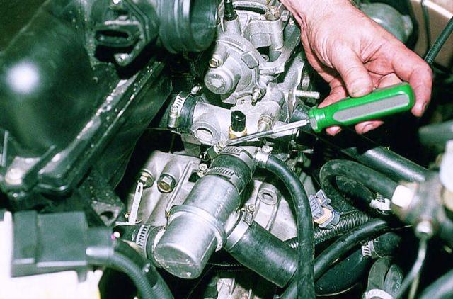
2. Remove the coolant temperature sensor.
3. Remove the exhaust manifold heat shield.
4. Remove the exhaust manifold.
5. Remove the exhaust manifold gasket.
6. Remove the exhaust manifold retaining studs.
7. Remove the spark plugs.
8. Remove the intake manifold.
9. Remove the intake manifold gasket.
10. Remove the intake manifold studs.
11. Unscrew the screws on the thermostat housing.
12. Remove the thermostat housing.
13. Remove the thermostat gasket and thermostat.
14. Using a valve spring compressor, compress the valve springs.
15. Remove the crackers and remove the upper valve spring plates.
16. Remove the valve springs.
17. Remove the valve stem seals.
20. Remove the camshaft housing centering sleeves.
For the engines described, the manufacturer provides for the restoration of the pair "guide sleeve - valve stem" by using valves with repair dimensions of the stems. In this case, the worn out bushing is restored by the deployment method to repair dimensions. Work of this complexity should only be entrusted to a qualified mechanic.
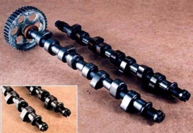
Lift the intake cams
Lifting the exhaust cams
Outer diameter of the camshaft journal
Outer diameter of the bearing
1. Clean the plane mating with the head gasket.
2. Check the cylinder head gasket and mating surfaces of the head and cylinder block for pits, traces of leaks, corrosion and gas breakthrough into the cooling jacket.
3. Check the cylinder head for cracks.
5. Determine, using a set of probes and a straight edge, the deviation from the flatness of the plane of the head mating with the gasket, which should not exceed 0.025 mm.
6. Measure the height of the block head. The cylinder head height must be between 94.70-95.65 mm g £ If the cylinder head height is less than 94.7 mm, it should be replaced.
7.Check all threaded holes for damage or dirt.
8. Inspect valve seats for excessive wear and burnout.
Valve drive control method
valve backlash compensator
Taper angle of the valve working surface (between the generatrix and the plane of the head)
Valve seat cone angle
Saddle working surface width
Valve guide inner diameter
Valve spring length under load
1. Determine the actual wear in the bushing-valve stem pair. With a gap exceeding 0.1 mm, this friction pair needs to be replaced. This diagnostic operation should only be performed by a qualified mechanic.
2. Oversize code is located on the valve guide and valve stem end. The table shows the standard and repair dimensions, the designation of the reamer used by authorized workshops, and the content of the codes applied to the bushings and valves. There are two types of codes: a code that is applied when assembling a new engine, and a code that is applied to the bushing during repair.
Code applied to parts of a new engine
Code applied to engine parts during repair
Reamer the bore of the guide bush. The direction of deployment is from the top of the cylinder head. Once deployed, cross out the code printed on the sleeve and re-code.
1. Finish the working surface of the valve seats.
The sealing surface of the valve seats is restored using three tapered cutters:
- cutter for processing the working surface of the saddle: 45 °;
- cutter for processing the upper correction angle: 30 °;
- cutter for processing the lower correction angle: 60 °;
Valve seat width:
- intake: 1.3-1.5 mm;
- outlet: 1.6-1.8 mm.
2. Check the position of the valve stem end after valve installation (this work should be done by a qualified mechanic without special gauges).
3. If the stem end is higher (closer to the camshaft axis), replace the valves with new ones and then check the position of the stem end again.
4. If the end of the valve stem is still higher despite replacing the valves, replace the cylinder head.
1. Inspect the valve for wear, pinching of the top end of the stem.
2. Inspect the grooves of the valve cotters and oil seal for wear.
3. Inspect the valve heads for burnouts and cracks.
4. Inspect valve stems for wear, scoring and scratches.
5. Inspect the valve stem - it shouldn't. wives have contortions.
6. Inspect the valve plug-in cone. If the wear of the contact cone is so great that surface repair will result in a sharp edge at the junction of the tapered and flat surfaces of the valve head, the valve should be replaced.
7. Inspect the valve spring. If the ends of the valve spring are not parallel, replace the valve spring.
8. Measure the height of the valve spring. If the valve spring height is out of specification, replace the valve spring.
9. Inspect the valve spring seating surfaces for wear or grooving. Replace if necessary.
1. Make sure there is no burnout on the valve head cone.
2. The valve can only be reground twice. Do not grind the end of the valve stem.
3. The angle between the generatrix of the valve cone and the plane of the head is 46 ″.
Lapping valves
If the development of the closing cone of the valve is not too large, the valve should be rubbed against the restored closing cone of the valve seat (as a rule, during the operation of the valve, the closing surface of the connecting rod bearings becomes wider: up to 4-5 mm). If, at the same time, there is no deep groove on the cone, then it is possible to grind the valve to the restored seat without grinding the cone.
The valve is lapped using special lapping pastes based on corundum.
In this case, the valve, installed in the guide sleeve, performs reciprocating movements with simultaneous right-left rotation, alternately. Such movements are necessary to form oblique lapping lines, located crosswise. During the lapping process, periodically rotate the valve in the seat to ensure even lapping. Lapping is complete when a uniform matte gray annular contact strip is formed on the seating surface of the valve, equal to the width of the seating surface of the seat.
1. Install the camshaft housing centering sleeves.
2. Lubricate the valve stems with engine oil.
4. Install the valve stem seals.
5. Install the valve springs.
6. Compress the valve springs and install the crackers.
7. Install the valve cover.
9. Install the thermostat housing
10. Install the thermostat housing screws and tighten them to 20 Nm.
11. Install the intake manifold studs.
12. Install the intake manifold gasket.
13. Install the intake manifold and tighten the nuts to 25 Nm.
14. Install the spark plugs and tighten to 40 Nm.
15. Install the exhaust manifold studs.
16. Install the exhaust manifold gasket.
17. Install the exhaust manifold and tighten the nuts to 25 Nm.
18. Install the exhaust manifold heat shield and tighten the screws to 15Nm.
19. Install the coolant temperature sensor and tighten to 20 Nm.
20. Install the cylinder head with the intake manifold and the exhaust manifold.
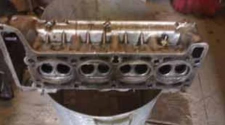
We will make an independent revision of the VAZ 2105 engine block head. Parts that were installed on the car by the manufacturer wear out during operation and need to be replaced. Tuning the cylinder head is a complex process, you need to approach such work as seriously as possible. First of all, we dismantle the block head and inspect its condition.
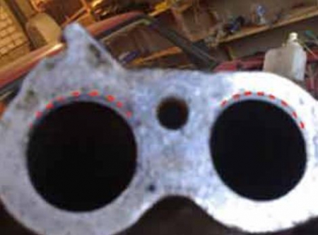
We work in an arc, without stopping in place, slowly move into the depths of the channels, its shape should not have sharp curves, humps and other irregularities, and the radius inside the channels should be as large as possible. Moving on, we check the mates with the valve seats. Be careful not to damage the chamfer of the valve seat. From the side of the combustion chambers, it will not be superfluous to make rounding in the channels. As for the guides, here you first need to draw a line on it, along which it sticks out in the channel. Our task is to remove the protruding metal as much as possible and at the same time leave the maximum area of the channel from the inside. Not everything is simple with exhaust manifolds, there is a heavy load, heat dissipation and the direction of flow is greater. It is recommended to bring only used valves, because new ones are practically impossible to cut. We hammer into place quickly, but neatly. Do not forget to remove the camshaft pin, they will get in the way. Let's go back to the cylinder head. The diameter of the holes can be increased from the manifold side. We grind to the guide bushings, then we do the processing from the side of the combustion chambers, while trying not to damage the valve seats. After the revision has been completed, everything is thoroughly washed and dried. Assembly is carried out upside-down.
Any experienced car owner will tell you that a stable cylinder head is a guarantee of the reliable functioning of a car engine. The cylinder head of the VAZ 2107 in good condition reduces fuel consumption and improves the dynamics of the car.
Inexperienced car owners should know that head repair work should be carried out only by highly qualified specialists. Otherwise, an incorrectly adjusted unit can lead to damage to many engine components. Refurbishment work can cost a lot. But experienced motorists with the required skills can replace, repair and pull the cylinder head bolts on their own.
The following symptoms may indicate a malfunction of the cylinder head on the VAZ 2107:
- the engine is troit;
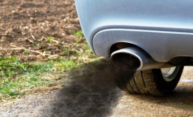
- black smoke coming out of the exhaust pipe;
Many malfunctions are resolved after pulling the bolts, but if this does not help, then a major overhaul of this unit may be necessary, involving the removal of not only the cylinder head, but also other parts of the block. Some parts may need to be replaced such as gaskets, valve stem seals and valve guides.
For work we need the following tools:
| Video (click to play). |
Before starting work on the repair of the cylinder head, it must first be removed and cleaned of dirt.
- The first step is to drain the coolant from the engine.
- We remove the carburetor.
- Having disconnected the pipes and hoses, we remove the air barrier.
Having previously set the marks with a marker, remove the rockers.
This video shows the process of removing the cylinder head.
Now it's time for the valves to dry out. This is done with a special device. If chips, cracks, rust are not visible, we carry out further inspection. We assess the condition of the saddles, the repair of which is recommended every two hundred thousand kilometers.
We inspect the guide bushings, in case of their unsatisfactory condition, they must be replaced.
A special tool is used to extract them. If this is not at hand, then you can do with pliers and a clamp. Having removed the bushings, we measure their diameter. We buy similar ones, the size of which is 0.05-0.07 millimeters larger than the replaceable ones.
The guides are pressed in with a mandrel, an electric stove, a hammer and grease.
- We put the head on a stand along the edges.
- We put an electrical device under the place of work.
- We are waiting for the metal to heat up to about a hundred degrees (so that it expands).
- Now you need to properly lubricate the bushing with grease.
- Having removed from the holders, we drive in new guides.
- When all eight are replaced, we are waiting for the cooling of the cylinder head.
- The valves should not dangle and move freely, there should not be any jamming.
To achieve a snug fit between the valves and the seats, the following must be done. Using a lapping paste, lubricate the valve and insert it into the head. There are several ways to rotate it, here are some of them:
- using a hose tightly fitted to the part;
- using a device very similar to a corkscrew.
The key to a good lapping valve will be the specific matte surface of the seat where it contacts the part.
The tightness of the head can be checked by pouring kerosene into the manifolds, you can also use gasoline. If done correctly, then there should be no leaks for the first five to seven minutes.
Attention! All engine parts must be washed with a special solution, this will ensure long-term and uninterrupted operation of the power plant for a long time.
When assembling the head, be sure to pay attention to the correct pulling of the bolts. It should be carried out strictly according to the scheme.In the event of an incorrect feed, distortions may appear and, as a result, all your previous work will be crossed out. If you have any questions, watch the video.
This video shows the repair of the cylinder head and the replacement of used parts.
Overhaul of the engine, or the eyes are afraid, but the hands are doing.
Background.
It all started, as you know, with the purchase of a "new" car in 2009. Car VAZ 21053 1997 color "safari" code 215 (for those who do not know - light beige). After the purchase, I skated no more than a couple of thousand kilometers and soon the move refused to pull normally. I checked the candles - relatively clean, adjusted the valves - it did not help. Having procured a homemade compression meter, and measured the compression, I was unpleasantly surprised.
The compression was as follows:
1 — 8;
2 — 8;
3 — 4,5;
4 — 8.
Here it is a no brainer that only an autopsy will save the patient. Like many brothers in misfortune, he began by calling the services, and, having learned the cost of the repair (15-17 thousand rubles only for work), he unanimously decided to make repairs with the forces of his limbs and gray matter.
And so, the age-old question, to which I did not find a detailed answer on the forums: "Capital of the engine, what and how to do?".
I'll start, perhaps, with a list of special tools that you may need for this ritual:
• set of heads;
• a mandrel for piston rings (about 260 rubles, but you can collect it yourself from a sheet of tin);
• mandrel for valve stem seals (20 rubles);
• valve desiccant (80-100 rubles);
• torque wrench (it is necessary to take such that the size of the square is the same as on the heads) (1300r);
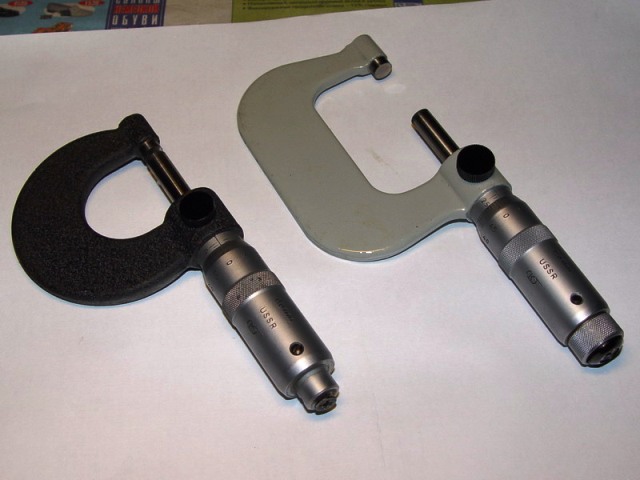
• micrometer (500-600 rubles);
• mandrel of the clutch disc (50 rubles);
• a device for adjusting valves with a hour indicator (500-800 rubles);
• two- or three-legged stripper (400-500 rubles).
For spare parts:
• pistons;
• piston rings;
• main and connecting rod inserts;
• crankcase gasket;
• block laying;
Literature:
• Repair manual for your car;
• spare parts catalog (of course, rare in our days, but you can find it on the internet)
The engine capital has been completed. Now you need to drive the first 2500 km carefully without sudden accelerations, without overloading the engine. After driving 2500 km, change the engine oil. Look under the hood frequently to check the unit.
Advice for those who will disassemble the cylinder head.
As you know, a regular drying agent is not a very convenient thing and easily flies out of the engagement on a hairpin. I advise you to tighten two nuts on the hairpin and clamp the grip of the device between them, then the chance of getting the device on the forehead will be minimal.
Removing the cylinder head on the car
The cylinder head is removed from the engine on a car if it is not necessary to remove the engine itself to eliminate the malfunction, or if it is only necessary to remove carbon deposits from the surfaces of the combustion chamber and valves. It is necessary to remove the cylinder head from the engine in the following order:
- drain the coolant from the radiator and cylinder block and remove the air filter;
- disconnect the wires from the battery, carburetor, spark plugs and from the coolant temperature gauge sensor;
- disconnect the throttle linkage from the intermediate lever on the cylinder head cover;
- disconnect the choke cable from the carburetor;
- disconnect the hose from the tube for supplying liquid to the heater, and from the exhaust manifold - the bracket for fastening the tube for removing the liquid from the heater;
- disconnect the hoses from the carburetor, inlet pipe and from the outlet pipe of the cylinder head cooling jacket;
- disconnect the starter shield and the front exhaust pipe from the exhaust manifold;
Note. The exhaust manifold and intake manifold with carburetor are best left on the head. They can be removed later when disassembling the cylinder head.
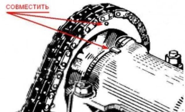
- turn the crankshaft until the mark “C” is aligned with the mark “D” on the middle protective cover, and the marks “F” on the camshaft pulley with the mark “E” on the cylinder head cover;
- remove the upper protective cover of the camshaft belt drive and the cylinder head cover;
- remove the spring 3 of the tension roller, loosen the mounting bolts of the bracket 2, move it to the extreme left position and remove the belt from the camshaft pulley;
- unscrew the fastening nuts and remove the bearing housing together with the camshaft, oil seal holder and pulley;
- unscrew the bolts securing the cylinder head to the block and remove the head with a gasket.
Installing the cylinder head
Install the gasket, the cylinder head on the cylinder block and tighten the cylinder head bolts in two steps in a certain sequence (according to the diagram): first, all the bolts to a torque of 33.3-41.16 N. m (3.4-4.2 kgf.m), and then 95.94 -118.38 N. m (9.79 - 12.08 kgf.m).
Thoroughly clean the mating surfaces of the cylinder head and the camshaft oil seal holder from the remnants of the old gasket, dirt and oil. Apply SUPER THREE BOND # 50 liquid gasket or KLT-75T sealant to the surface of the cylinder head mating with the oil seal holder with a continuous 2 - 2.5 mm diameter bundle.
Note. After applying a liquid gasket, it is allowed to start the engine no earlier than 1 hour later.
Check if the mark on the crankshaft pulley is against the long mark on the middle protective cover of the camshaft drive belt.
Turn the camshaft so that the marks on the pulley and bearing housing are aligned. Without knocking down the position of the shaft, fix the assembled bearing housing on the cylinder head by tightening the nuts in the specified sequence.
Place the belt over the camshaft pulley. Install the idler roller bracket spring. Turn the crankshaft smoothly two turns, keeping the belt in constant tension and without loosening the belt when the shaft stops. Tighten the idler roller bracket mounting bolts.
Check the alignment of the labels. If the marks do not match, then repeat the installation of the belt.
Adjust the clearance between the camshaft cams and the valve levers.
Install the cylinder head cover with gasket and fuel line bracket. Tighten the cover retaining nuts in the specified sequence. Install the upper camshaft belt guard.
Attach the starter shield and the front exhaust pipe to the exhaust manifold.
Connect the hoses to the carburetor, inlet pipe, cylinder head cooling jacket outlet and to the heater fluid supply pipe.
Connect the throttle actuator rod to the intermediate arm on the cylinder head cover. Connect the choke cable to the carburetor.
Reconnect the removed wires and fill the cooling system with fluid.
Check and adjust the ignition timing.
Disassembly and assembly
Install the cylinder head on board A.60335.
Disconnect the cooling jacket outlet and the heater fluid outlet.
Disconnect the exhaust manifold and intake manifold with carburetor (hot air intake is removed at the same time).
Remove the levers 11 (Fig. Above) of the valves, freeing them from the springs. Remove the springs of the levers.
Install the A.60311 / R tool as shown in the figure below, squeeze the calpan springs and release the crackers. Instead of the portable device А.6ОЗ 11/11, the stationary device 02.7823.9505 can also be used.
Remove the valve springs with poppets and support washers. Turn the cylinder head and remove the valves from the bottom.
Remove the valve stem seals from the guide bushings.
Unscrew the spark plugs with the key 67.7812.9515.
Assemble the cylinder head in reverse order.
Cleaning the cylinder head
Place the head on the stand A.60353.
Carefully remove carbon deposits from all combustion chambers and all exhaust ports with a wire brush powered by an electric drill.Clean and inspect all valve arm oil inlets and oil passages.
Checking and grinding valve seats
The valve seat chamfer shape is shown in the figures below.
On the working chamfers of the seats (the contact area with the valves) there should be no pinholes, corrosion and damage. Minor damage can be repaired by grinding the seats. In doing so, remove as little metal as possible. Grinding can be done either by hand or with a grinder.
Sand in the following order:
- install the head on the support A.60353, insert the rod A.94059 into the valve guide sleeve and clean the chamfers of the seats from carbon deposits with countersinks A.94031 and A.94092 for exhaust valve seats and with countersinks A.94003 and A.94101 for inlet valve seats. Countersinks are put on the spindle А.94058 and are centered by the guiding rod А.94059;
Note. Rods A.94059 exist in two different diameters: A.94059 / 1 - for the guides of the intake valves and A. 94059/2 - for the guides of the exhaust valves.
- put the spring A.94069 / 5 on the guide rod A.94059, install the tapered disc A.94078 for the exhaust valve seats or the disc A.94100 for the inlet valve seats on the spindle A.94069, fix the spindle in a grinder and grind the valve seat ( (see figure below).
At the moment the wheel touches the saddle, the machine must be turned off, otherwise vibration will occur and the chamfer will be incorrect.
It is recommended to dress the wheel more often with a diamond.
For exhaust valve seats, bring the width of the working chamfer to the values indicated in the figure (see above) with a 94031 countersink (angle 20 °), and A.94092 countersink, which removes work hardening on the inner diameter. Countersinks are put on the spindle А.94058 and, as in grinding, are centered with the rod А.94059.
At the inlet valve seats, bring the width of the working chamfer to the values indicated in the figure (see above), first machining the internal chamfer with A.94003 countersink (Fig. Below) until a diameter of 33 mm is obtained, and then a 20 ° chamfer with A.94101 countersinks to obtaining a working chamfer with a width of 1.9-2 mm.
Remove carbon deposits from valves (fig. Below). Check carefully if the rod is deformed or cracked on the plate. If damage or defects are found, the valve must be replaced.
Check if the working chamfer is too worn or damaged. When grinding the working chamfer of the valve on a grinding machine, maintain a chamfer angle of 45 ″ 30 '+ 5 ′ and make sure that the thickness of the cylindrical part of the valve disc after grinding is not less than 0.5 mm, and also that the exhaust valve does not have a layer of hard removed alloy overlaid on a chamfer.
Valve guides
Check the clearance between the guide bushings and the valve stem by measuring the diameter of the valve stem and the bore of the guide bush.
Design clearance for new bushings: 0.022-0.055 mm for intake valves and 0.029-0.062 mm for exhaust valves; the maximum allowable limit clearance (with wear) is 0.15 mm.
If the increased clearance between the guide bush and the valve cannot be eliminated by replacing the valve, replace the valve bushings using a mandrel A .60153 / R (Fig. Below).
To replace the two intake and exhaust valve guides for cylinders # 1 and # 4, unscrew the two camshaft bearing housing retaining pins as they interfere with the mandrel installation.
Press in the guide bushings with the retaining ring put on until the ring stops in the plane of the cylinder head.
After pressing in, open the holes in the guide bushings with reamers A.90310 / I (for bushings of inlet valves) and A.90310 / 2 (for bushings of exhaust valves). Then grind the valve seat and adjust the bevel width to the desired dimensions as described above.
Oil deflector seals of guide bushings
At the valve stem seals, rubber peeling from the reinforcement, cracks and excessive wear of the working edge are not allowed.
When repairing the engine, it is recommended to always replace the valve stem seals with new ones, even if the old ones are not defective or damaged.
It is recommended to replace damaged valve stem seals on the removed cylinder head so as not to bend the valve stems. Use mandrel 41.7853.4016 to press on the caps.
Valve levers
Check the condition of the working surfaces of the lever in contact with the valve stem, the camshaft cam and the ball end of the adjusting bolt. If these surfaces are scored or scratched, replace the lever with a new one.
If deformation or other damage is found to the adjusting bolt bushing or bolt itself, replace the parts.
Make sure the springs are not cracked and the spring elasticity has not decreased, for which check the deformation of the springs under load (pictures below).
For lever springs (figure below), dimension A (spring in a free state) should be 35 mm, and dimension B under a load of 51-73.5 N (5.2-7.5 kgf) - 43 mm.
The engine of the "seven" has a working volume of 1500 cm 3, which provides the car with good technical characteristics. Intensive and long-term operation of the VAZ 2107 car leads to wear of the cylinder-piston group and the gas distribution mechanism. Medium and overhaul repairs involve the removal of a faulty head and the dismantling of many parts from the cylinder block. Many parts will also need to be replaced, including the gasket, valve stem seals and valve guides.
To carry out repair work on the VAZ 2107 engine, you will need the following tools and accessories:
- Micrometer for measuring and detecting parts.
- Mandrels for disassembly and installation of new valve guides and valve stem seals.
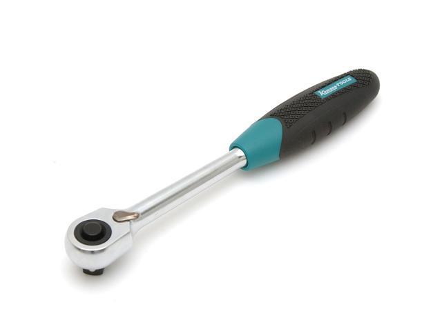
- Torque wrench.
- Closed spiral tile.
- Valve spring compressor.
Repair work on the cylinder head is preceded by removing it from the cylinder block, cleaning it from dirt and then replacing defective elements.
Performing work of this kind requires a fairly high qualification and special equipment. Removal of the cylinder head is carried out in the following sequence:
- The car is installed in a garage box, the battery is disconnected.
- The following elements are dismantled from the engine: air filter housing, carburetor and head cover.
- The upper timing sprocket is unscrewed from the camshaft and removed.
- With the help of the head and a powerful wrench, the head fastening bolts are turned out.
- After that, the assembly is carefully removed from the cylinder block.
- The gasket remains on the surface, or rather its remnants, they must be removed while using a non-metallic tool to avoid damage.
On VAZ 2107 engines, gaskets made of a fire-resistant composition are used. After dismantling the head during the repair process from the cylinder block, it is necessary to transfer it to the workbench for inspection and repair. It is necessary to start with a thorough examination and inspection of all assemblies to identify parts with significant deviations from the nominal values. All such parts will need replacement parts.
The head of the VAZ 2107 block is installed on a wooden stand on the desktop. It plays the role of fixing the fixing valve when disassembling them. Defective parts are removed and replaced; all gaskets are also subject to renewal. At this stage, the preparation for the repair preparation can be considered complete.
The cylinder head of a VAZ 2107 car is made of aluminum, which made it possible to simplify the processing of parts and reduce the total weight of the power unit. The repair head is removed from the cylinder block and placed on the work table. With the help of it, the crankshaft in the housing with sleeve bearings is dismantled.
The next stage of the restoration work on the VAZ 2107 engine units is the removal of the valves and the replacement of the guide bushings.For this, devices are used to compress the springs and tweezers to take out the biscuits. The valves are removed from the sockets and the stem diameter is measured with a micrometer. With significant deviations from the nominal, they change together and the guides. The remnants of the old gasket are removed from the mating surface with a scraper made of soft material. It should be remembered that aluminum is soft enough and the head can be easily damaged.
The assembly of the cylinder head begins with the installation of new guides and the assembly of valve mechanisms. Then a new gasket is installed on the surface of the cylinder block. An assembled and tested head is installed on it, which is attached with bolts. Tightening is done with a torque wrench in the prescribed manner. The last step is to replace the valve box cover gasket.


