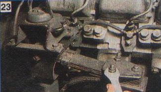
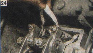
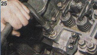
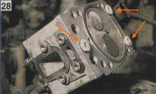
In detail: do-it-yourself repair of a KAMAZ euro head from a real master for the site my.housecope.com.
TECHNOLOGICAL CARD № 1.4.
REPAIR OF THE CYLINDER HEAD OF THE KAMAZ-740 ENGINE
Total labor intensity - 57.0 people. min
DISASSEMBLY OF THE CYLINDER HEAD OF THE KAMAZ-740 ENGINE
Labor intensity - 17.0 people. min
1. Install the cylinder head assembly onto the disassembly tool. (Workbench for locksmiths, device for disassembling and assembling the head).
2. Unbend the antennae of the lock washer securing the rocker arm strut. (Hammer, chisel).
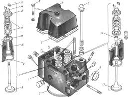
3. Unscrew the nuts 18 (Fig. 1) fastening the rocker arm axle struts. (Replaceable head 17 mm, wrench with p. K.).
4. Remove the rocker arm post, lock washers and rocker retainer.
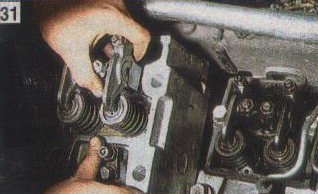
5. Remove the rocker arms 8 (Fig. 2) of the valves from the rocker arm post.
6. Unscrew and remove the nut 7 from the adjusting screw and unscrew the adjusting screw 5 of the rocker arm. (Wrench 17 mm, screwdriver 10.0 mm).
7. Remove the cylinder head from the disassembly tool. (Workbench for locksmiths, device for disassembling and assembling the head).
8. Install the cylinder head on the valve remover).
9. Rotate the handle 2 to squeeze the spring plate 12 (Fig. 1) together with the bushing 11, and remove the 10 valve crackers, 11 valve spring plates, valve spring plates 12, outer 13 and inner 14 springs and 16 valve spring washers. (Screwdriver 10.0 mm).
10. Remove the sealing collar 15 (Fig. 4) of the inlet valve assembly with the collar ring 16 from the guide sleeve 18 of the inlet valve. (Screwdriver 10.0 mm).
11. Remove the inlet 20 and outlet 1 valves.
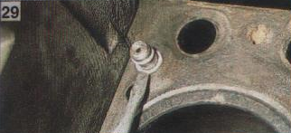
12. Unscrew the screw 29 fastening the intake manifold and the screw 30 fastening the water pipe.
| Video (click to play). |
Perform work if necessary to replace the screwdriver. (Key for turning the screw-in
return the studs 21 for attaching the exhaust manifold pipe, studs 26 for attaching the rocker arm struts and pins 24 for attaching the injector bracket. Perform the work if necessary to replace the studs. (Tool for unscrewing the studs).
14. Remove cylinder head 31 from the tool. (Valve remover).
WASHING THE CYLINDER HEAD PARTS
15. Rinse the removed parts and the cylinder head, clean the valve, valve seats, valve guides, the block head and blow them off with compressed air. (Installation for washing parts model 196 M or "Typhoon", metal brush; metal brushes, sandpaper No. 280-320, gun for blowing parts with compressed air mrd S-417).
DEFECTIVE CYLINDER HEAD PARTS
16. Defect the parts of the cylinder head. Troubleshooting should be performed according to the troubleshooting card No. 1.3.
17. Install the cylinder head on a stand for crimping the head, check the head tightness and, if necessary, eliminate the leakage. Check at a pressure of 0.4 MPa (4 kgf / cmg) for 2 minutes. Fluid leaks and leaks are not allowed. (Stand for crimping, stopwatch).
Each head of the Kamaz-740 block is installed on two locating pins, pressed into the cylinder block, and fastened with four alloy steel bolts.
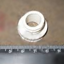
One of the locating pins simultaneously serves as a bushing for supplying oil to lubricate the rocker arms. The sleeve is sealed with rubber rings.
In the Kamaz-740 cylinder head, in comparison with the 740.10 engine head, the engine oil drain hole from under the valve cover into the rod cavity is increased. The intake and exhaust ports are located on opposite sides of the cylinder head.
The inlet channel has a tangential profile to ensure optimal rotational movement of the air charge, which determines the parameters of the working process and the environmental performance of the engine, therefore, replacement with the cylinder heads of the 740.10 engine is not allowed.
Cast iron seats and sintered valve guides are pressed into the head of the Kamaz-740 cylinder block. The valve seats have an increased interference fit compared to the 740.10 engine seats, and are fixed with a sharp edge.
The outlet seat and valve are profiled to provide less resistance to exhaust gas discharge. The use of outlet valve 740.10 is not recommended.
The joint "cylinder head - sleeve" Kamaz-740 (gas joint) is unlined. A steel O-ring is pressed into the bore groove on the lower plane of the head.
Through this ring, the Kamaz-740 cylinder head is installed on the liner collar. The tightness of the seal is ensured by high precision machining of the mating surfaces of the O-ring and the cylinder liner.
The O-ring has an additional lead coating to compensate for the roughness of the sealing surfaces.
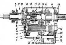
1 - cylinder head, 2 - head cover gasket, 3 - cover fastening bolt, 4 - cylinder head cover, 5 - head fastening bolt, 6 - pipe gasket bushing, 7 - gas joint sealing ring, 8 - intake valve, 9 - saddle valve, 10 - valve guide sleeve, 11 - valve spring washer, 12 - external and internal valve springs, 13 - valve spring plate, 14 - disc bushing, 15 - valve cracker, 16 - sealing collar, 17 - inlet valve
The cylinder heads contain the valve mechanism and the injector. The valve mechanism of the head is closed by an aluminum cover, sealed with a gasket. Cast iron seats and sintered valve guides are bored after being pressed into the head.
Each head is secured to the cylinder block with four bolts. To avoid breaking the tightness of the gas joint, the bolts are tightened in a cross pattern in three steps.
The inlet and outlet ports are located on opposite sides of the head. When looking at the engine from the side, the intake valves of the heads are on the right, and the exhaust valves are on the left.
The inlet channel has a tangential profile, providing a vortex movement of air in the cylinder, improving mixture formation and accelerating the combustion process of the injected fuel. The injector socket is located on the side of the exhaust valve at an angle to the cylinder axis.
It is necessary to remove the cylinder head quite often. At least every 40-50 thousand kilometers. This is how the KamAZ engine is structurally arranged. Leaking coolant or oil is the cause. Dismantling the cylinder head will also be required to repair the piston group or the gas distribution mechanism.
Let's take a step-by-step and detailed look at the process of dismantling the head of the KamAZ 740 engine block.
1. Drain at least half of the coolant from the cooling system.
2. To dismantle the heads of the block of some cylinders, it will be necessary to dismantle the coolant expansion tank and the compressor.
3. Remove the intake and exhaust manifolds, and also unscrew all interfering fuel pipes.
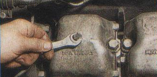
4. Unscrew the bolt securing the block head cover with a 13 key.
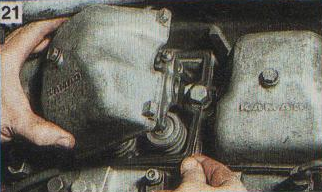
5. Remove the cover and gasket.
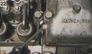
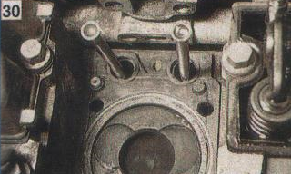
9. Unscrew the four bolts securing the head to the block using a 19 socket or box wrench.
11. The head should be cleaned of dirt and carbon deposits. After that, replace the three O-rings ("barrels") of the water holes.
12.Place a new O-ring on the oil channel bushing.
The final tightening torque of the bolts of the KamAZ 740 engine block head is 16-18 kgf * m.
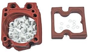
The kit consists of:
1.740.1003 040 Oil channel sealing ring - 16 pcs.
2. 740.1003 214-04 Sealing ring (cylinder head) "barrel", installed in the holes of the coolant channels - 24 pcs.
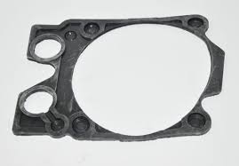
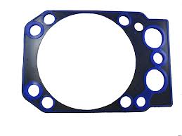
3.740.1003 213-26 Cylinder head gasket - 8 pcs.
4.740.1003270 Cylinder head sealing cover gasket - 8 pcs.
Cylinder head gaskets can be old or new.
Taking into account the interchangeability of the heads of the KamAZ 740 engine block, it is preferable for repairs to replace the cylinder head with a new one.
If necessary, repairs are often carried out:
- Replacing valve seats.
- Seat machining - valve lapping.
- Saddle socket boring.
- Plane restoration
Since the discussion is in this thread, I will add:
The cylinder heads were the same and the gas joint O-ring was of a different shape. It, as it were, pressed the steel gasket for a fracture into the sleeve. Therefore, the cylinder head, without replacing the gas joint ring, were not interchangeable.
Sealing gas joint with steel ring:
1 - support ring; 2 - steel cylinder head gasket; 3 - cylinder head; 4 - rubber sealing gasket; 5 - cylinder block; 6 - sleeve sealing ring; 7 - cylinder liner.
Gas joint seal without steel ring:
1 - cylinder head; 2 - gas joint sealing ring; 3 - gasket; 4 - cylinder liner
Since October 1984, a gas joint seal without a steel ring has been introduced. The tightness of the gas joint is ensured by high precision machining of the surfaces of the ring and cylinder liner. To compensate for the microroughness of the mates, a lead coating is applied to the mating surface of the gas joint ring.
1. cylinder head housing:
reinforced bottom
additional rib
tangential inlet
overload saddles
2.valve - different profile and material composition
3.The rods are 3mm shorter
4. ring of gas joint for "filler"
+ remember - the valve stroke on the euro motor is more than 740.10
1. cylinder head housing:
reinforced bottom
additional rib
tangential inlet
overload saddles
2.valve - different profile and material composition
3.The rods are 3mm shorter
4. ring of gas joint for "filler"
+ remember - the valve stroke on the euro motor is more than 740.10
Again the mechanicus is muddying.
1. is possible.
2.The profile of the valves is the same, interchangeable.
3. it depends on the block and the camshaft, at the moment "same type" blocks are produced for the "Euro" camshaft, that is, the rods are now short both in euro and in simple.
5. the rings of the gas joint are identical.
+ Once again, the dimensional parameters of the camshafts are now the same, both for euros and for simple ones, so the valve travel has become the same.
On my own I note that the cooling cavity of the nozzle is increased on the euro heads, the other parameters seem to be the same.
In practice, I can say; heads are interchangeable, some "comrades" prefer to install simple heads on the euro motor (they are cheaper).
1. cylinder head housing:
reinforced bottom
additional rib
tangential inlet
overload saddles
2.valve - different profile and material composition
3.The rods are 3mm shorter
4. ring of gas joint for "filler"
+ remember - the valve stroke on the euro motor is more than 740.10
Nikk! The motors of the E3 line of the 740.60 series are equipped with a cylinder head of increased strength, i.e. This applies both to the material of the valve bushings and to the material of the body, i.e. brand of aluminum. Look at the heads you changed, maybe the valves with the guides just “sat down” because of such a load and temperature. Also, do not forget that the E3 heads have an original intake channel, which can affect the filling of the cylinders with air, etc. , which in turn affects the CPG and just after a long time.
Uv.Engineer - I ask you to provide not empty words, but documentary evidence refuting those differences (which, by the way, have technical confirmation and documentary ground) that were indicated here.
1. cylinder head housing:
reinforced bottom
additional rib
tangential inlet
overload saddles
2.valve - different profile and material composition
3.The rods are 3mm shorter
4. ring of gas joint for "filler"
+ remember - the valve stroke on the euro motor is more than 740.10
Again the mechanicus is muddying.
1. is possible.
2.The profile of the valves is the same, interchangeable.
3. it depends on the block and the camshaft, at the moment "same type" blocks are produced for the "Euro" camshaft, that is, the rods are now short both in euro and in simple.
5. the rings of the gas joint are identical.
+ Once again, the dimensional parameters of the camshafts are now the same, both for euros and for simple ones, so the valve travel has become the same.
On my own I note that the cooling cavity of the nozzle is increased on the euro heads, the other parameters seem to be the same.
In practice, I can say; heads are interchangeable, some "comrades" prefer to install simple heads on the euro motor (they are cheaper). [/ quote]
Let's take a look at the points, everything that is written here is taken not from the ceiling, but from many years of practice.
And yet, for some reason it seems to me that you have never seen a simple head of a new sample. On this let me ask one question; What is the difference between the new-type head and the old-style head? If you have dealt with them in practice, then you can easily answer the question.
The engine of KamAZ 740 cars is designed in such a way that its own head is installed on each cylinder of the block. Accordingly, under each Cylinder head KamAZ there is a separate gasket that ensures its tight fit to the block, or rather the tightness of the water and oil channels.
However, in consequence, temperature exposure, incorrect installation, Bad quality and a number of other destructive factors, breakdown (burnout) of such gaskets quite often happens. Therefore, replacing the gasket under one or more heads is quite a common procedure.
- leakage of oil or coolant from under the head to the outside... The most common option for KamAZ vehicles. It is detected by the presence of streaks on the block. Often, due to the exhaust manifold, it is difficult to determine unambiguously which of the heads "leaked". After dismantling it, it becomes clear which of the heads needs to be removed.
- exit from under the head of the exhaust gases, which is manifested by a rather loud soundtrack when the engine is running. Quite a rare occurrence for the KamAZ engine. Considering that the function of sealing the head and cylinder (combustion chamber) is taken over by the steel ring of the gas joint, the gasket will burn out as a result of damage to this part. If the ring seat has not been deformed, it will need to be replaced. Otherwise, it may be necessary to replace the head with a new one.
- after dismantling the cylinder head for any of the above reasons, and for cylinder head repair, gas distribution and crank mechanism, replacement of the worn-out head bolt to the block, etc.
In addition to the rubber gasket, for each head it will be necessary to replace 2 O-rings on the bushings of the oil channels, as well as 3 seals for the water holes, which have the shape of a "barrel", for which they are nicknamed in the jargon of auto technicians. The gas joint can be provided with a fluoroplastic gasket.
Also, it may be necessary to replace the valve cover gasket and gaskets under the intake and exhaust manifolds.
- Before starting work, you will need to drain at least half of the total volume of the coolant. And also, dismantle the interfering expansion tank and compressor.
- Using a 19 wrench, unscrew the union nuts of the high pressure pipe from the injection pump section
- Also, it is necessary to unscrew the fuel pipe from the injector of the head to be dismantled.
- Using a spanner or socket wrench 14, unscrew the union of the drain tube of the injectors and remove it.
- Dismantle the water pipe using a 13 socket wrench and the intake manifold with a 17 socket wrench.
- Using a 13 key, unscrew the bolt securing the valve cover of the block head. And remove the cover along with the gasket. You will also have to remove the adjacent cover, the protrusion of which will interfere with the dismantling of the cylinder head of the block.
The tightening torque must be:
- the first reception - 39 ... 49 N m (4 ... .5 kgf m);
- the second reception - 98 ... 127 N m (10 ... 13 kgf m);
- the third reception - 186 ... 206 N m (19 ... 21 kgf m) the limiting value.
After tightening the bolts, it is necessary to adjust the clearances between the valves and the rocker arms. The clearance is necessary to ensure a tight fit of the valve to the seat during thermal expansion of parts during engine operation.
Small repair of the KamAZ head.
cylinder head kamaz cylinder head kamaz cylinder head repair kamaz
Detailed disassembly of the KamAZ 740 engine!
Ural 4320 part 10. Repair, lapping valves engine kamaz 740
I rub the valves on the KAMAZ head with an interesting device
repair of fuel injection pump kamaz with your own hands without a stand
A simple (old-fashioned) way of adjusting the KamAZ 740 valves. And a long-awaited purchase!
Frequent valve head problems on a kamaz engine
Valve adjustment KamAZ 740
If you love your KamAZ and undertook to provide it with emergency technical assistance with your own hands, do not forget that when servicing trucks you need to follow certain rules and sequence of actions, especially when it comes to its engine or removable engine elements.
Lapping engine valves
To ensure that the valves are lapped in, the valve train must be disassembled. Now you need to carry out the procedure for preparing a special paste. It will consist of three components in a certain ratio. Half of the paste will be green silicon carbide micropowder, 1/3 of the volume will be diesel oil and 1/6 will be diesel fuel. Immediately before use, the already prepared lapping paste must be thoroughly mixed in order to stir up the micropowder, which tends to precipitate.
Now apply a thin layer of paste to the chamfer of the valve seat carefully and evenly. Do not forget to clean the valve stem with a cloth that has been previously soaked in engine oil. Lapping is carried out by the reciprocating movement of the valve using a drill fitted with a suction cup or similar. When the valve is pressed, it turns in a circular motion, first by 1/3 of a turn, and then by ¼ of a turn, only in the opposite direction. The grinding process does not stop until a uniform matte belt appears on the chamfers of the valve and seat, the width of which is at least 1.5 mm.
Checking the quality of valve lapping
At the end of the lapping procedure, the valves and cylinder head are flushed with diesel fuel and blown with air. The valve train can now be reassembled. In doing so, the quality of the valve lapping should be determined using a standard tightness test.
Such a check begins with the fact that the cylinder head is installed in turn, the intake and exhaust ports are upwards, and diesel fuel is poured into them. If the valves are lapped well, then they do not allow fuel to pass through the seals for 30 seconds. If the fuel still leaks, take a rubber mallet and tap it on the end of the valve. If this does not help and the leakage continues, the valves are lapped again.
Also, the quality of lapping can be checked by applying marks (5 pieces, maximum 8) with a soft graphite pencil perpendicular to the chamfer of the valve at approximately the same distance from each other. The valve is now gently pushed into the seat with a push and a ¼ turn. It is necessary that all marks are erased, if this does not happen, grinding the valves also requires a second procedure.
In case of an immediate need to repair the engine, you can do it yourself, guided by some manuals or instructions.
Repair work with a KamAZ engine consists of many procedures and tricks that will help prolong the life of your car. Below are presented.
When the engine fails, you can do a lot of work to fix its malfunctions. The main thing is to first figure out what is the reason for these.
Timely identification of truck engine malfunctions, as well as knowledge of the causes of specific signs of damage to parts, helps.
In case of a certain malfunction in the KamAZ engine, it is possible to independently provide the unit with all the necessary maintenance,.
We replace the cylinder head gaskets when a coolant and oil leak appears in the connection between the cylinder head and the cylinder block.
To do the job, we need a tool: keys 8x10, 12x13, 17x19, 22x24, 27x30, replaceable heads for 13, 14, 17, 19 mm, a knob, a knob blade, a screwdriver, a chisel, a hammer, a flat scraper, a jack, a stand, dishes for fuel, oil and coolant, torque wrench.
First of all, we disconnect the electric wires from the batteries.
We drain the coolant.
We unscrew the bolts and remove the cover of the front hatch of the clutch housing.
Raise the front of the car and place the support under the first frame cross member.
Unscrew the drainage pipeline (return line) with a 14 head and a wrench, Figure 1.
We unscrew the high pressure pipes from the engine injectors.
We unscrew the high-pressure pipes from the injection pump, Figure 3.
We loosen the tightening of the exhaust manifold mounting bolts (Fig. 4).
Remove the intake manifolds.
Unscrew the bolts with a 13 head and disconnect the thermostat box flange.
If the valve does not fit snugly against the seat, gaps will form in some areas of the valve and seat. In this case, gases under pressure and at high speed pass into the formed slots, therefore, in this place the chamfers are subjected to strong corrosion and the adhesion of the valve to the seat deteriorates. Combustion products accumulate on the surface of the valve chamfer, as a result of which the tightness of the connection is broken.
We replace the valve stem seals with increased oil consumption and with the next repair of the cylinder heads.
Removing and lapping valves
We install the cylinder head on the workbench or on the base of the I801.06.000 puller, if available. If there is no such a puller as in the picture (Fig. 1), then you can use a puller for VAZ cars (Fig. 2).
Before compressing the springs, tap the spring plates with a hammer to make the locking crackers come out easier. We squeeze the valve springs until the crackers come out of the bushing cone completely and remove the crackers.
Remove the sleeve 5 (Fig. 3), plate 7, springs 10 and 11, washer 13, and take out the valve.
Using pliers (Fig. 4), remove the valve stem seals.
We clean the valve and valve seats from carbon deposits and clean the rest of the parts in diesel fuel.
The angles of inclination of the working chamfers should be within the limits of the saddle = 44˚45 ′; at the valve 45˚30 '. These angles are set when restoring the cylinder head and valve before lapping.
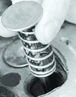
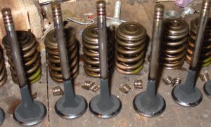
We put a pre-selected spring on the valve stem (Fig. 5) and insert the valve into the guide sleeve from the side of the combustion chamber, lubricating the valve stem with a layer of graphite grease. The graphite grease prevents abrasive from the lapping paste from getting into the guide bore holes and facilitates the rotation of the valve during lapping.
We put on the valve stem a device for grinding the valves (or with some tightness a rubber tube to connect the valve with a reversible drill).
Apply a uniform thin layer of lapping paste to the working surface of the valve chamfer.
Turning on the drill at the minimum speed (in reverse mode) or rotating the device (in the case of manual lapping) alternately in both directions by half a turn, we grind the valve, periodically pressing it against the seat, then weakening the pressing force.
We continue grinding until a uniform matte band with a width of at least 1.5 mm appears on the chamfers of the valves and seats.
We wash the valve seats and valves in diesel fuel, blow them with compressed air and check the quality of lapping. To check the quality of lapping, apply six to eight dashes with a soft pencil across the valve chamfer at an equal distance, insert the valve into the seat and, pressing firmly, turn it a quarter of a turn. If all lines are worn out, then the valve is worn in well.
Cylinder head assembly
We insert the valves into the guide bushings, lubricating them with engine oil. Install washers 13 (Fig. 3).
Using the tool (Fig. 6), press in the valve stem seals.
We install the springs, spring plates and, compressing the springs, insert the locking crackers.
After installing the crackers and removing the valve spring compressor, apply a few gentle blows with a hammer to the end of the valve stem so that the crackers are guaranteed to be fixed in the groove in the stem. If the skewed crackers are left unsecured, when the engine is started, the "dry" valve will fall into the cylinder, which will lead to a serious engine accident.
We check the tightness of the valves. We put the head with the combustion chambers up, and pour a little kerosene along the shoulder into the combustion chamber. If, within 3 minutes, kerosene does not seep into the head channel, the valve is sealed. When kerosene leaks, we lightly tap with a rubber hammer on the end of the valve. If the leakage persists, we rub the valves again.
Timely prevention is a sure way to prevent breakdowns, therefore, for a KamAZ-type truck, maintenance and repair work is carried out strictly according to the schedule drawn up on the basis of factory recommendations. The initial period of operation of the new KAMAZ, set by the manufacturer, is one thousand kilometers. During this stage, it is important to observe the speed limit (no more than fifty kilometers / hour) and avoid excessive load on the truck (no more than 75% of the norm).
Any configuration of a new KAMAZ is accompanied by the necessary documentation, which includes a manual for its repair.
Scheduled car repairs are carried out in order to prevent significant breakdowns. One of the main preventive measures is the regular replacement of all automotive fluids (coolant, lubricant and brake) in systems selected in accordance with the standards and requirements of the manufacturer. The occurrence of leaks in the cooling system, violation of the integrity of the valves and tank gaskets are breakdowns that the driver must eliminate immediately.
Delays in repairs can cause cavitation damage in the structure of the unit and pump, which will negatively affect the operation of the entire vehicle.
In case of a signal notification of a decrease in pressure in the lubrication system, it will be necessary to urgently repair the KAMAZ engine by the driver's own forces. Further movement of the truck with such a breakdown is undesirable.
Operation of a vehicle with a violation of the tightness of the intake tract of the internal combustion engine system can lead to premature wear of the car engine.
Preventing cracks in the cylinder head mountings will require reliable isolation of the bolt holes to prevent internal fluid and contamination from entering. The described manipulations are also recommended when replacing the cylinder heads of the internal combustion engine.
Certain repairs require welding. An important point in their implementation is to disconnect the battery. At the same time, the positive contact is removed from the generator. In this case, the ground wire of the welding machine should be connected at a short distance from the weld.
Regular maintenance of the car and its preventive inspection allow you to forget about the problem of breakdowns occurring along the way and the need to eliminate them. It is recommended to inspect the main parts of KAMAZ before each trip, as well as to check the level of all working fluids in its systems.
The driver independently performs the following actions:
- checks the integrity of the wheels and tire pressure;
- checks the functioning of the steering system drive;
- tests the response of the brake system.
It is recommended to carry out scheduled technical inspections of KAMAZ in a car service at least twice a calendar year. The seasonality of such events is due to the preparation of the truck for use in the summer and winter periods.
Under proper operating conditions of the vehicle, repair work is required much less frequently. There are specific recommendations to the driver regarding situations that arise unexpectedly on the road:
- if a coolant leak is detected in the system, water can be topped up. This measure is from the category of forced ones, allowing the driver to get to the place where a full-fledged repair is being carried out;
- when towing a truck with an inoperative engine, it is imperative to remove the propeller shaft. Ignoring this requirement will lead to scuffing of the bearings of the gears of the output shaft in the gearbox, which will subsequently require early repair of the gearbox;
- when the car is driving on a road filled with liquid mud for a long time, it is recommended to rinse the radiator surface from time to time under a strong pressure of water. To do this, you will need to raise the KAMAZ cab and carefully, without getting water on the generator, carry out the manipulation. Regular flushing will prevent radiator repair work for the foreseeable future.
42 posters that will surely come in handy when repairing a KAMAZ with your own hands
KAMAZ 5320 and Ural-4320 vehicles. Tutorial.
For cadets of technical schools and vocational technical schools, drivers and workers of transport organizations.
Do-it-yourself maintenance and repair of KAMAZ
Repair and maintenance manual
DIY KAMAZ car repair
| Video (click to play). |


