In detail: do-it-yourself repair of a KamAZ head from a real master for the site my.housecope.com.
TECHNOLOGICAL CARD № 1.4.
REPAIR OF THE CYLINDER HEAD OF THE KAMAZ-740 ENGINE
Total labor intensity - 57.0 people. min
DISASSEMBLY OF THE CYLINDER HEAD OF THE KAMAZ-740 ENGINE
Labor intensity - 17.0 people. min
1. Install the cylinder head assembly onto the disassembly tool. (Workbench for locksmiths, device for disassembling and assembling the head).
2. Unbend the antennae of the lock washer securing the rocker arm strut. (Hammer, chisel).
3. Unscrew the nuts 18 (Fig. 1) fastening the rocker arm axle struts. (Replaceable head 17 mm, wrench with p. K.).
4. Remove the rocker arm post, lock washers and rocker retainer.
5. Remove the rocker arms 8 (Fig. 2) of the valves from the rocker arm post.
6. Unscrew and remove the nut 7 from the adjusting screw and unscrew the adjusting screw 5 of the rocker arm. (Wrench 17 mm, screwdriver 10.0 mm).
7. Remove the cylinder head from the disassembly tool. (Workbench for locksmiths, device for disassembling and assembling the head).
8. Install the cylinder head on the valve remover).
9. Rotate the handle 2 to squeeze the spring plate 12 (Fig. 1) together with the bushing 11, and remove the 10 valve crackers, 11 valve spring plates, valve spring plates 12, outer 13 and inner 14 springs and 16 valve spring washers. (Screwdriver 10.0 mm).
10. Remove the sealing collar 15 (Fig. 4) of the inlet valve assembly with the collar ring 16 from the guide sleeve 18 of the inlet valve. (Screwdriver 10.0 mm).
11. Remove the inlet 20 and outlet 1 valves.
12. Unscrew the screw 29 fastening the intake manifold and the screw 30 fastening the water pipe.
| Video (click to play). |
Perform work if necessary to replace the screwdriver. (Key for turning the screw-in
return the studs 21 for attaching the exhaust manifold pipe, studs 26 for attaching the rocker arm struts and pins 24 for attaching the injector bracket. Perform the work if necessary to replace the studs. (Tool for unscrewing the studs).
14. Remove cylinder head 31 from the tool. (Valve remover).
WASHING THE CYLINDER HEAD PARTS
15. Rinse the removed parts and the cylinder head, clean the valve, valve seats, valve guides, the block head and blow them off with compressed air. (Installation for washing parts, model 196 M or "Typhoon", metal brush; metal brushes, emery paper No. 280-320, a gun for blowing parts with compressed air mrd S-417).
DEFECTIVE CYLINDER HEAD PARTS
16. Defect parts of the cylinder head. Troubleshooting should be performed according to the troubleshooting card No. 1.3.
17. Install the cylinder head on a stand for crimping the head, check the head tightness and, if necessary, eliminate the leakage. Check at a pressure of 0.4 MPa (4 kgf / cmg) for 2 minutes. Fluid leaks and leaks are not allowed. (Stand for crimping, stopwatch).
If you love your KamAZ and undertook to provide it with emergency technical assistance with your own hands, do not forget that when servicing trucks you need to follow certain rules and sequence of actions, especially when it comes to its engine or removable engine elements.
Lapping engine valves
To ensure that the valves are lapped in, the valve train must be disassembled. Now you need to carry out the procedure for preparing a special paste. It will consist of three components in a certain ratio. Half of the paste will be green silicon carbide micropowder, 1/3 of the volume will be diesel oil and 1/6 will be diesel fuel.Immediately before use, the already prepared lapping paste must be thoroughly mixed in order to stir up the micropowder, which tends to precipitate.
Now apply a thin layer of paste to the chamfer of the valve seat carefully and evenly. Do not forget to clean the valve stem with a cloth that has been previously soaked in engine oil. Lapping is carried out by the reciprocating movement of the valve using a drill fitted with a suction cup or similar. When the valve is pressed, it turns in a circular motion, first by 1/3 of a turn, and then by ¼ of a turn, only in the opposite direction. The grinding process does not stop until a uniform matte belt appears on the chamfers of the valve and seat, the width of which is at least 1.5 mm.
Checking the quality of valve lapping
At the end of the lapping procedure, the valves and cylinder head are flushed with diesel fuel and blown with air. The valve train can now be reassembled. In doing so, the quality of the valve lapping should be determined using a standard tightness test.
Such a check begins with the fact that the cylinder head is installed in turn, the intake and exhaust ports are upwards, and diesel fuel is poured into them. If the valves are lapped well, then they do not allow fuel to pass through the seals for 30 seconds. If the fuel still leaks, take a rubber mallet and tap it on the end of the valve. If this does not help and the leakage continues, the valves are lapped again.
Also, the quality of lapping can be checked by applying marks (5 pieces, maximum 8) with a soft graphite pencil perpendicular to the chamfer of the valve at approximately the same distance from each other. The valve is now gently pushed into the seat with a push and a ¼ turn. It is necessary that all marks are erased, if this does not happen, grinding the valves also requires a second procedure.
In case of an immediate need to repair the engine, you can do it yourself, guided by some manuals or instructions.
Repair work with a KamAZ engine consists of many procedures and tricks that will help prolong the life of your car. Below are presented.
When the engine fails, you can do a lot of work to fix its malfunctions. The main thing is to first figure out what is the reason for these.
Timely identification of truck engine malfunctions, as well as knowledge of the causes of specific signs of damage to parts, helps.
In case of a certain malfunction in the KamAZ engine, it is possible to independently provide the unit with all the necessary maintenance,.
Each head of the Kamaz-740 block is installed on two locating pins, pressed into the cylinder block, and fastened with four alloy steel bolts.
One of the locating pins simultaneously serves as a bushing for supplying oil to lubricate the rocker arms. The sleeve is sealed with rubber rings.
In the Kamaz-740 cylinder head, in comparison with the 740.10 engine head, the engine oil drain hole from under the valve cover into the rod cavity is increased. The intake and exhaust ports are located on opposite sides of the cylinder head.
The inlet channel has a tangential profile to ensure optimal rotational movement of the air charge, which determines the parameters of the working process and the environmental performance of the engine, therefore, replacement with the cylinder heads of the 740.10 engine is not allowed.
Cast iron seats and sintered valve guides are pressed into the cylinder head of the Kamaz-740. The valve seats have an increased interference fit compared to the 740.10 engine seats, and are fixed with a sharp edge.
The outlet seat and valve are profiled to provide less resistance to exhaust gas discharge. The use of outlet valve 740.10 is not recommended.
The joint "cylinder head - sleeve" Kamaz-740 (gas joint) is unlined. A steel O-ring is pressed into the bore groove on the lower plane of the head.
Through this ring, the Kamaz-740 cylinder head is installed on the liner collar. The tightness of the seal is ensured by high precision machining of the mating surfaces of the O-ring and the cylinder liner.
The O-ring has an additional lead coating to compensate for the roughness of the sealing surfaces.
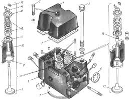
1 - cylinder head, 2 - head cover gasket, 3 - cover fastening bolt, 4 - cylinder head cover, 5 - head fastening bolt, 6 - pipe gasket bushing, 7 - gas joint sealing ring, 8 - intake valve, 9 - saddle valve, 10 - valve guide sleeve, 11 - valve spring washer, 12 - external and internal valve springs, 13 - valve spring plate, 14 - disc bushing, 15 - valve cracker, 16 - sealing collar, 17 - inlet valve
The cylinder heads contain the valve mechanism and the injector. The valve mechanism of the head is closed by an aluminum cover, sealed with a gasket. Cast iron seats and sintered valve guides are bored after being pressed into the head.
Each head is secured to the cylinder block with four bolts. To avoid breaking the tightness of the gas joint, the bolts are tightened in a cross pattern in three steps.
The inlet and outlet ports are located on opposite sides of the head. When looking at the engine from the side, the intake valves of the heads are on the right, and the exhaust valves are on the left.
The inlet channel has a tangential profile, providing a vortex movement of air in the cylinder, improving mixture formation and accelerating the combustion process of the injected fuel. The injector socket is located on the side of the exhaust valve at an angle to the cylinder axis.
It is necessary to remove the cylinder head quite often. At least every 40-50 thousand kilometers. This is how the KamAZ engine is structurally arranged. Leaking coolant or oil is the cause. Dismantling the cylinder head will also be required to repair the piston group or the gas distribution mechanism.
Let's take a step-by-step and detailed look at the process of dismantling the head of the KamAZ 740 engine block.
1. Drain at least half of the coolant from the cooling system.
2. To dismantle the heads of the block of some cylinders, it will be necessary to dismantle the coolant expansion tank and the compressor.
3. Remove the intake and exhaust manifolds, and also unscrew all interfering fuel pipes.
4. Unscrew the bolt securing the block head cover with a 13 key.
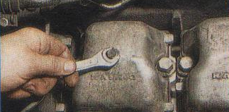
5. Remove the cover and gasket.
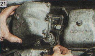
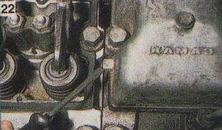
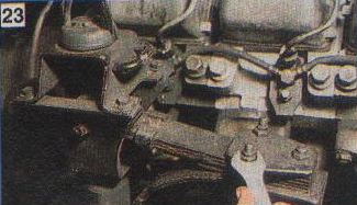
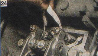
9. Unscrew the four bolts securing the head to the block using a 19 socket or box wrench.
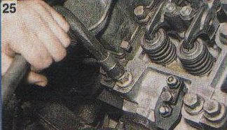
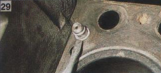
11. The head should be cleaned of dirt and carbon deposits. After that, replace the three O-rings ("barrels") of the water holes.
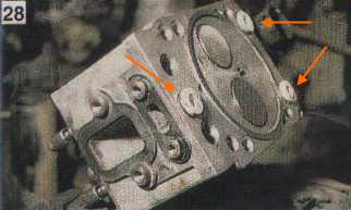
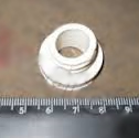
12.Place a new O-ring on the oil channel bushing.
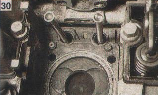
The final tightening torque of the bolts of the KamAZ 740 engine block head is 16-18 kgf * m.
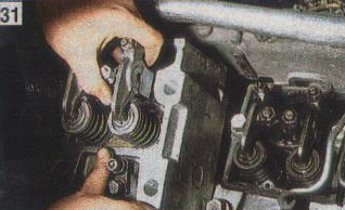
The kit consists of:
1.740.1003 040 Oil channel sealing ring - 16 pcs.
2. 740.1003 214-04 Sealing ring (cylinder head) "barrel", installed in the holes of the coolant channels - 24 pcs.
3.740.1003 213-26 Cylinder head gasket - 8 pcs.
4.740.1003270 Cylinder head sealing cover gasket - 8 pcs.
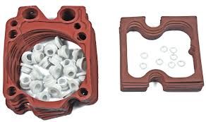
Cylinder head gaskets can be old or new.
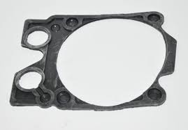
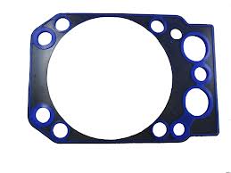
Taking into account the interchangeability of the heads of the KamAZ 740 engine block, it is preferable for repairs to replace the cylinder head with a new one.
If necessary, repairs are often carried out:
- Replacing valve seats.
- Seat machining - valve lapping.
- Saddle socket boring.
- Plane restoration
The engine of KamAZ 740 cars is designed in such a way that each cylinder of the block has its own head. Accordingly, under each Cylinder head KamAZ there is a separate gasket that ensures its tight fit to the block, or rather the tightness of the water and oil channels.
However, in consequence, temperature exposure, incorrect installation, Bad quality and a number of other destructive factors, breakdown (burnout) of such gaskets quite often happens. Therefore, replacing the gasket under one or more heads is quite a common procedure.
- leakage of oil or coolant from under the head to the outside... The most common option for KamAZ vehicles. It is detected by the presence of streaks on the block. Often, due to the exhaust manifold, it is difficult to determine unambiguously which of the heads "leaked". After dismantling it, it becomes clear which of the heads needs to be removed.
- exit from under the head of the exhaust gases, which is manifested by a rather loud soundtrack when the engine is running. Quite a rare occurrence for a KamAZ engine. Considering that the function of sealing the head and cylinder (combustion chamber) is taken over by the steel ring of the gas joint, the gasket will burn out as a result of damage to this part. If the ring seat has not been deformed, it will need to be replaced. Otherwise, it may be necessary to replace the head with a new one.
- after dismantling the cylinder head for any of the above reasons, and for cylinder head repair, gas distribution and crank mechanism, replacement of the worn-out head bolt to the block, etc.
In addition to the rubber gasket, for each head it will be necessary to replace 2 O-rings on the bushings of the oil channels, as well as 3 seals for the water holes, which have the shape of a "barrel", for which they are nicknamed in the jargon of auto technicians. The gas joint can be provided with a fluoroplastic gasket.
Also, it may be necessary to replace the valve cover gasket and gaskets under the intake and exhaust manifolds.
- Before starting work, you will need to drain at least half of the total volume of the coolant. And also, dismantle the interfering expansion tank and compressor.
- Using a 19 wrench, unscrew the union nuts of the high pressure pipe from the injection pump section
- Also, it is necessary to unscrew the fuel pipe from the injector of the head to be dismantled.
- Using a spanner or socket wrench 14, unscrew the union of the drain tube of the injectors and remove it.
- Remove the water pipe using a 13 socket wrench and the intake manifold with a 17 socket wrench.
- Using a 13 key, unscrew the bolt securing the valve cover of the block head. And remove the cover along with the gasket. You will also have to remove the adjacent cover, the protrusion of which will interfere with the dismantling of the cylinder head of the block.
The tightening torque must be:
- the first reception - 39 ... 49 N m (4 ... .5 kgf m);
- the second reception - 98 ... 127 N m (10 ... 13 kgf m);
- the third reception - 186 ... 206 N m (19 ... 21 kgf m) the limiting value.
After tightening the bolts, it is necessary to adjust the clearances between the valves and the rocker arms. The clearance is necessary to ensure a tight fit of the valve to the seat during thermal expansion of parts during engine operation.
Small repair of the KamAZ head.
cylinder head kamaz cylinder head kamaz cylinder head repair kamaz
Detailed disassembly of the KamAZ 740 engine!
Ural 4320 part 10. Repair, lapping valves engine kamaz 740
I rub the valves on the KAMAZ head with an interesting device
repair of fuel injection pump kamaz with your own hands without a stand
A simple (old-fashioned) way of adjusting the KamAZ 740 valves. And a long-awaited purchase!
Frequent valve head problems on a kamaz engine
Valve adjustment KamAZ 740
Repair, service and device, cylinder heads KAMAZ vehicle.
The cylinder head is mounted on a 7831-4044 disassembly / assembly tool or workbench. Having unbent the tendrils of the lock washer securing the rocker arm strut, unscrew the fastening nuts of the rocker arm axle struts and remove the rocker arm strut, lock washers and the rocker arm retainer, and then the rocker arms 11 (see Fig. 5.15) of the valves from the rocker arm post. Having unscrewed and removed the nut 10 of the adjusting screw, screw in the adjusting screw 8 of the rocker arm, remove the cylinder head from the device for disassembly-assembly and install it on the device for removing and installing the valves (Fig.5.18) so that the pins 4 enter the holes for the head bolts.
Rice. 5.18. Dismantling the cylinder head in the I-801.06.000 tool:
1 - screw; 2 - handle; 3 - valve plates; 4 - pin; 5 - cylinder head
By rotating the handle 2, the device squeezes the plates 14 (see Fig. 5.11) of the valve springs together with the bushings 7 and remove the crackers 8 of the valves, the plates with bushings, the outer 5 and inner 6 springs and the washers 4 of the valve springs. From the guide sleeve 18 of the intake valve, remove the sealing lip 17 in the assembly, after which the intake valves 20 and exhaust valves 1 are removed from the cylinder head.
If it is necessary to replace, unscrew the following parts: screw-in 27 for fastening the intake manifold, screw-in 26 for fastening the water pipe, studs 21 for fastening the exhaust manifold pipe, studs 30 for fastening the rocker arms and studs 32 for fastening the nozzle bracket. The cylinder head is removed from the tool.
The cylinder head and removed parts are washed, valves, seats and valve guides are cleaned of carbon deposits, parts are blown with compressed air and defective.
The cylinder head is installed on a pressure testing stand 470.085 and checked under an air pressure of 0.3 MPa (3 kgf / cm 2) for 2 minutes. the tightness of the cooling jacket and under pressure of 0.6. 0.65 MPa (6.6.5 kgf / cm 2) - tightness of oil channels. If air leaks, the cylinder head is discarded. It is also subject to rejection in the presence of cracks capturing the internal channels, cavities of the holes for the nozzle, guide bushings and the interface with the cylinder block, with the destruction of the seats for the valve seats and the bridges between them, with damage or cavitation destruction of the interface with the cylinder block.
The weakening of the seating of the valve seats in the seats is detected with light blows with a copper hammer. In the presence of this defect and wear of the seats for the inlet valve seats to a diameter greater than 55.03 mm, and the exhaust valve seats - 52.03 mm, the seats for the inlet valve seats are machined to a repair size of 55.5 + (0.03) mm, and the exhaust valve seats - 52 .5 + (0.03) mm. In the event of a weakening of the seating of the valve seats in the seats previously machined to the oversize, the cylinder head is rejected. Similarly, the weakening of the fit of the valve guides is determined and eliminated. The limiting diameter of the hole for the guide bush is 18.04 mm, the overhaul dimension is 18.4 + (0.023) mm.
In the presence of a working surface or cavities on the working surface of the valve seats, they are processed before removing the defect by lapping, preventing an increase in the diameter of the outlet valve seat by more than 43 mm, and the inlet valve - 48 mm. If it is impossible to eliminate the defect, the seats are replaced.
If there are cracks, chips, mechanical damage on the surface of the valve guide bushings, as well as when the hole in the guide bushing is worn up to a diameter of more than 10.04 mm, the bushing is replaced. The gas joint sealing ring must also be replaced if it burns out or is mechanically damaged.
The cylinder head cover is discarded if there are breaks and cracks. The flatness of the contact surface with the cylinder head is checked with a feeler gauge on a surface plate. It should be no more than 0.15 mm. Otherwise, the surface is treated until the defect is eliminated, removing a metal layer of no more than 0.5 mm. If it is impossible to eliminate the defect, the part is rejected.
The rocker arm of the valve with the bushing assembly is rejected if there are breaks or cracks, as well as when the toe of the rocker arm is worn in height. The distance from the horizontal, passing through the center of the hole in the bushing of the rocker arm, to the toe of the rocker arm, should be no more than 6.0 mm. When the hole in the bushing is worn out, it is replaced and processed to a repair size in accordance with the repair size of the rocker arm strut (Table 5.2).
The rocker rack is discarded if there are breaks or cracks. When the supporting surfaces are worn out, they are processed to a repair size (see Table 5.2), with a diameter of more than 24.66 mm, they are rejected.
The inlet and outlet valves are rejected in the presence of cracks, breaks, wear or burnout of the working chamfer of the valve. If the inlet valve stem is worn down to a diameter of less than 9.94 mm, and the outlet valve is 9.90 mm in diameter, the valve is rejected or sent for restoration. In case of uneven wear of the end of the valve stem, it is processed until the defect is eliminated, avoiding a decrease in the height from the end to the annular groove in excess of 6.3 mm. If it is impossible to eliminate the defect, the valve is rejected.
After eliminating the defects, the cylinder head assembly with valve guide bushings is placed on a 7831-4044 disassembly-assembly device or a workbench and installed in place, if they were removed, the following parts: studs 21 (see Figure 5.11) fastening the exhaust manifold pipe ( protrusion height of the studs 52 ± 1 mm), studs 32 for fastening the nozzle brackets, studs 30 for fastening the rocker arms, screw 27 for fastening the intake manifold and screw 26 for fastening the water pipe. The cylinder head is removed from the assembly tool and placed on a valve grinding stand with valve seats facing up.
Having prepared a lapping paste from 81% granular electrocorundum and 13% paraffin, diluted in M10G2k engine oil to a creamy state, apply the paste to the working surface of the valve seats. Having installed the inlet and outlet valves in the cylinder head, they are lapped until a continuous matte belt with a width of at least 1.5 mm appears on the chamfers of the valve and seat, without scratches and breaks on the surface of the belt. When properly lapped, the matte shoulder on the saddle should start at the base of the large cone of the saddle.
The cylinder head and valves are placed in a container, the cells of which are numbered and ensure that the valves and seats, to which they are ground, are retained. Parts are washed in KM-1 washing solution with EAP-40 defoamer. Concentration KM-1 - 5 g / l, EAP-40 - 0.2. 0.3%. The composition of the washing solution: sodium carbonate - 22.5%, trisodium phosphate - 18.9%, sodium tripolyphosphate - 50.6%, sulfanol - 2.3%, synthanol DT-7 - 5.7%. The temperature of the washing solution is 70. 80 ° С, the holding time is 2 min.
After washing, the cylinder head is installed on the valve removal and installation tool (see Fig. 5.18), the valve stems and the working surfaces of the guide bushings are lubricated with clean engine oil and the valves are installed in their places according to the numbering after lapping.
On the guide sleeve 18 (see Fig. 5.11) of the intake valve, a sealing collar 17 is assembled, 4 valve spring washers are installed, internal 6 and external 5 springs, valve spring plates 14 with bushings 7 and the rotation of the handle of the device compress the springs with plates and bushings ... Having installed the crackers of 8 valves, the springs are released, making sure that the crackers enter the sleeve 7.
After removing the cylinder head from the device, check the tightness of the valves. To do this, the cylinder head is installed alternately with the intake and exhaust ports upwards and diesel fuel is poured into them. Well-lapped valves should not allow fuel to pass through the seals for 30 seconds. If fuel leaks, tap the end of the valve with a rubber hammer. If the leakage persists, the valves must be ground in again. The quality of lapping can be checked with a pencil, for which six to eight lines are applied across the valve chamfer at an equal distance. The valve is inserted into the seat and, pressing firmly on it, is turned 1/4 turn. With a good lapping, all lines should be erased.
The cylinder head is mounted on a 7831-4044 assembly tool or workbench. Adjusting screws 8 (see Fig. 5.15) are screwed into the rocker arms and nuts 10 are screwed onto them without tightening. Then the rocker arms 11 are installed on the rocker arm struts, the rocker arm lock and the rocker arm assembly with the valve rockers - on the cylinder head. Having tightened the nuts for securing the rocker arm axle struts [tightening torque 42.54 N * m (4.2. 5.4 kgf * m)], the tendrils of the lock washer fastening the rocker arm strut are bent, after which they remove the cylinder head from the device and send it to the engine assembly ...
Repair, service and device, cylinder heads KAMAZ vehicle.
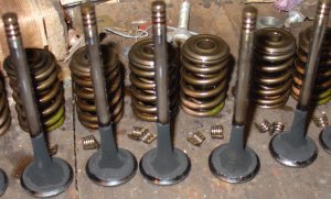

If you love your KamAZ and undertook to provide it with emergency technical assistance with your own hands, do not forget that when servicing trucks you need to follow certain rules and sequence of actions, especially when it comes to its engine or removable engine elements.
Lapping engine valves
To ensure that the valves are lapped in, the valve train must be disassembled. Now you need to carry out the procedure for preparing a special paste. It will consist of three components in a certain ratio. Half of the paste will be green silicon carbide micropowder, 1/3 of the volume will be diesel oil and 1/6 will be diesel fuel. Immediately before use, the already prepared lapping paste must be thoroughly mixed in order to stir up the micropowder, which tends to precipitate.
Now apply a thin layer of paste to the chamfer of the valve seat carefully and evenly. Do not forget to clean the valve stem with a cloth that has been previously soaked in engine oil. Lapping is carried out by the reciprocating movement of the valve using a drill fitted with a suction cup or similar. When the valve is pressed, it turns in a circular motion, first by 1/3 of a turn, and then by ¼ of a turn, only in the opposite direction.The grinding process does not stop until a uniform matte belt appears on the chamfers of the valve and seat, the width of which is at least 1.5 mm.
Checking the quality of valve lapping
At the end of the lapping procedure, the valves and cylinder head are flushed with diesel fuel and blown with air. The valve train can now be reassembled. In doing so, the quality of the valve lapping should be determined using a standard tightness test.
Such a check begins with the fact that the cylinder head is installed in turn, the intake and exhaust ports are upwards, and diesel fuel is poured into them. If the valves are lapped well, then they do not allow fuel to pass through the seals for 30 seconds. If the fuel still leaks, take a rubber mallet and tap it on the end of the valve. If this does not help and the leakage continues, the valves are lapped again.
Also, the quality of lapping can be checked by applying marks (5 pieces, maximum 8) with a soft graphite pencil perpendicular to the chamfer of the valve at approximately the same distance from each other. The valve is now gently pushed into the seat with a push and a ¼ turn. It is necessary that all marks are erased, if this does not happen, grinding the valves also requires a second procedure.
In case of an immediate need to repair the engine, you can do it yourself, guided by some manuals or instructions.
Repair work with a KamAZ engine consists of many procedures and tricks that will help prolong the life of your car. Below are presented.
When the engine fails, you can do a lot of work to fix its malfunctions. The main thing is to first figure out what is the reason for these.
Timely identification of truck engine malfunctions, as well as knowledge of the causes of specific signs of damage to parts, helps.
In case of a certain malfunction in the KamAZ engine, it is possible to independently provide the unit with all the necessary maintenance,.
1 VEHICLE ASSEMBLY TECHNOLOGY
1.1 Purpose of the structural features of the unit.
1.2 Technical conditions for the overhaul of the timing.
2. TECHNOLOGICAL PROCESS OF CYLINDER HEAD RESTORATION.
2.1 Purpose of the part
2.2 Brief description of the method for restoring a part.
2.3 Project of the route for the restoration of the block head.
2.4 Calculation of the processing mode of one operation.
3. Safety precautions when performing work
3.1. General requirements.
3.2. Requirements before starting work.
3.3. Requirements during work.
3.4. Requirements at the end of work.
3.5. Emergency requirements.
4. REFERENCES
Defect 1 - Cracks on the cooling jacket of any nature and location, with the exception of cracks passing through the threaded holes for the spark plugs.
Defect 2 - Cracks of any nature on the contact surface with the cylinder block, not passing through the combustion chamber.
Repair method: Bonding with epoxy resin paste.
1 - Carry out a hydraulic test of the cylinder head under the pressure of water heated to 600 C, 3-4 kg / cm2. Mark with chalk the location of the crack boundaries.
Electric hoist with a lifting capacity of 0.25 tons. Stand for hydraulic testing of cylinder heads.
Cylinder head hanger, set of tools for stand maintenance, chalk. Metal ruler 300 mm, seven-fold magnifier LP1-7.
- - Roll and drill the ends of the cracks with a 4 mm drill. Pack up the crack at an angle of 1200 to a depth of 0.7-0.8 of the wall thickness. Grind the surface to a metallic shine along each crack on both sides at a distance of 15-20 mm. Degrease the prepared surface. Heat the area of the cut crack to a temperature of 70-800C.
- Grind the bosses for the cylinder head nuts.Grind the surface of the head adjoining the block until the warpage is eliminated, but to a size not less than that allowed by the specifications for the cylinder head grading.
Surface grinding machine type 3B71M or 6H11, clamps for fastening the cylinder head.
Grinding wheel PP 350x50x127 GOST 2424-60 KCh No. 80-40 CM1 K, front attachment cutter with insert knives D 200-250 mm, mandrel for installing the cutter.
Test plate, set of probes No. 3 - No. 4, template for controlling the depth of the combustion chamber.
1. Explanatory note - A4.
2. Drawing of the driven gear wheel of the main transfer - A2:
3. Operating card - A4:
4. Operating card - A4;
5. Operating map of grinding - A4.
6. operational map of milling -A4.
7. Technology for disassembling the gas distribution mechanism - 1 -A1.
| Video (click to play). |
For the rest of the drawings, see the "Screens" folder, archive


