In detail: do-it-yourself repair of imported radio tape recorders from a real master for the site my.housecope.com.
Danny the section of the site is devoted to the issues of repairing car radios with your own hands. It's no secret that car players of various modifications and manufacturers break down.
Non the pages This section will not be a simple listing of specific malfunctions of certain car radio models, but methods of repair and restoration of these devices will be revealed. The presentation will be conducted without interrupting practice, with examples of repairing specific models of car turntables.
Introduction article. It describes the necessary devices that will be required in the process of repairing car radios.
How to connect a car radio or car CD / MP3 receiver to a computer power supply (PSU)? Anyone who wants to "power" a car radio from a 220V network faces this question. This makes sense if you plan to repair the car radio or upgrade it to a stationary music center.
Here you will learn about typical car player malfunctions and their causes.
What is a complex malfunction and how can error codes help in car radio repair? A real example of troubleshooting a complex malfunction of the Pioneer DEH-P3500MP car CD receiver.
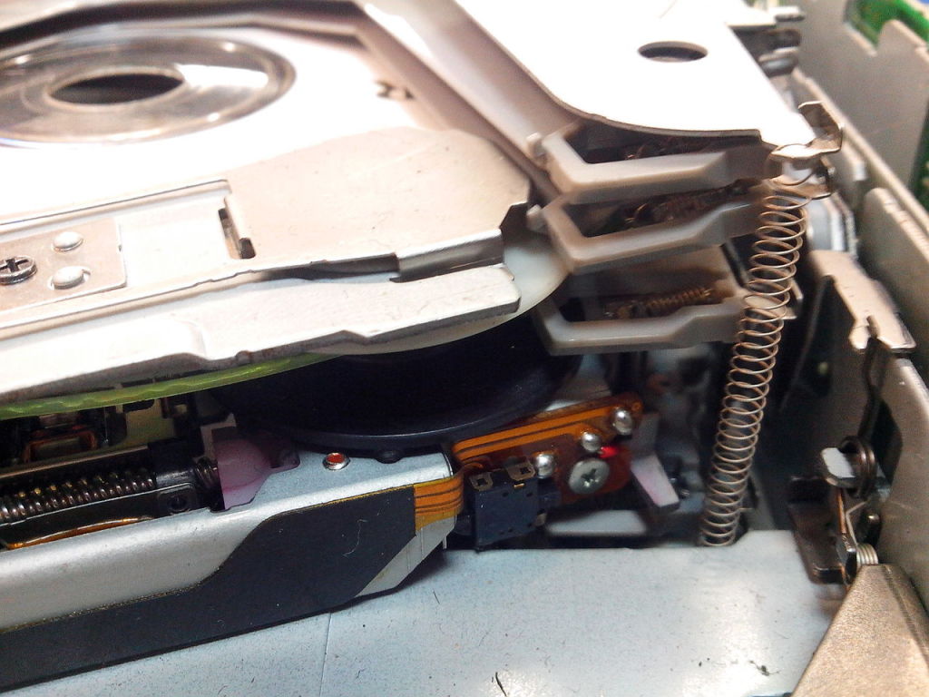
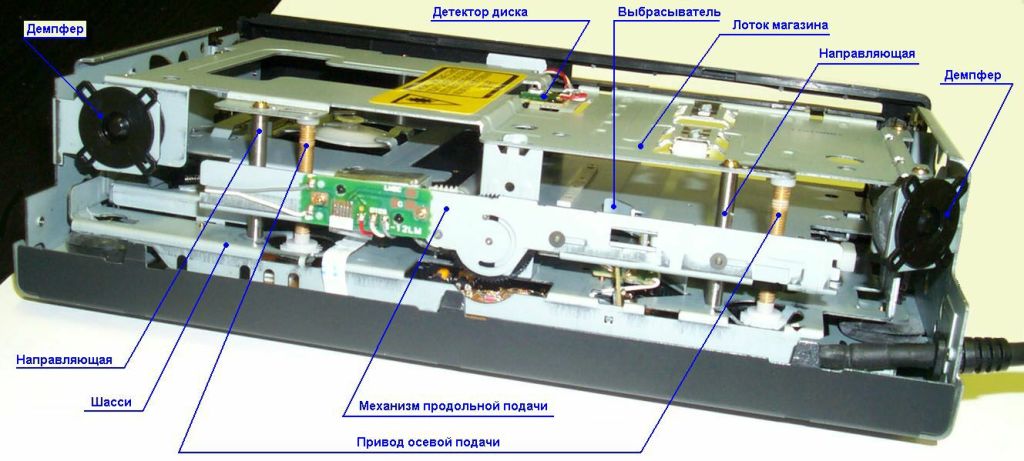
When repairing disc car radios, it is often necessary to disassemble the CD mechanism. Shown in detail is the method of disassembling the CD mechanism, which is widespread among modern car CD / MP3 players.
CD drives for car receivers of different brands differ in their design. This means that you need to be able to disassemble CD mechanisms of different types. Here you will learn how to disassemble the CD drive of the Kenwood car radio without errors.
| Video (click to play). |
An article that tells about one of the typical malfunctions of car CD / MP3-receivers - there is no display backlight. How to fix this breakdown will be discussed.
Here we talk about an atypical breakdown of the Mystery MCD-778MP car CD / MP3 receiver. A real example of repair using an oscilloscope.
The volume control of the car radio does not work? The knob may be the cause of the problem. The rotary encoder is very often used in digital equipment to adjust various functions and control the device. Is it really necessary to replace the rotary encoder if it does not work correctly? How to restore the correct operation of the knob and avoid replacing it is described in this article.
In the practice of repairing car players and CD-receivers, there are cases when a schematic diagram, information on the pinout of the connector or a table for decoding error codes is needed. This information is contained in the service manual for a specific car radio model. You can download the service manual for some models of popular car radios by clicking on the link above.
Which brand of car radio should you choose? Read this article and this question will disappear forever.
Find out about the device of SD / MP3 car receivers. Among all kinds of modifications of car radios, so-called flash car radios have found their place under the sun.This article examines the device and the elemental composition of car SD / MP3-receivers without a disk using the Velas V-201U model as an example.
The “POWER” LED (if any) on the front panel does not light up, there is no characteristic click in the speakers.
In this case, it is most logical to check the A / M power circuits in the following sequence: plus power supply - fuse - power switch - radio / tape recorder switch - other circuits (radio receiver unit, signal processing unit, tape recorder panel), first of all check the fuse. If it burns out, ring (relative to the case) for a short circuit the power filter elements, the power amplifier (s) (via the power bus), the filtering capacitors of the blocks. Often so-called breaking resistors are installed in the A / M, which are located between the supply network and the consumer of high currents (power amplifier, drive motor).
Burnout (charring) of this resistor indicates a short circuit in this unit. You should also visually check the integrity of the electrolytic capacitors.
On top of these capacitors there is a so-called cross-notch. A bulging or opening of a notch indicates a defective capacitor. Even if the A / M is working properly, the swollen capacitors will sooner or later show themselves, but with more unpleasant consequences. They should be replaced in any case.
You should also not forget about checking the car's on-board network. A significant excess of the voltage norm in the on-board network, as well as an increased level of interference, leads to many A / M malfunctions. Here it is necessary to check the voltage regulator, generator, noise suppression filters of the on-board network in the car. It often happens that in case of malfunctions of the on-board network, even already repaired vehicles fail again.
The car turns on, the motor is running in the tape recorder panel, the indication is on - there is no sound.
The volume control is out of order. In this case, it is enough to unsolder the regulator outputs and ring it.
The power amplifier (PA) or the separating capacitor between the PA and the dynamic heads is out of order, it is also possible that the lead wiring to the dynamic head breaks down, cutting off the speaker coils. When eliminating this malfunction, you should check the lead wires to the speakers, the isolating capacitor, the PA, as well as the absence of breakdowns on the case of the dynamic head coil (see Fig. 1), which overloads the PA and leads to its failure.
In the latter case, proceed as follows: connect an ohmmeter according to Fig. 2 and, carefully pressing on the speaker diffuser, make sure that there are no short circuits (Ohm) between the speaker case and the coil.
If this check is not done, a speaker defect can damage the PA again.
There is no sound in the A / M in the “Tape recorder” mode.
First of all, check the presence of the supply voltages of the magnetic head preamplifier and the drive motor. The absence of these voltages indicates a malfunction of the "RADIO - RECORDER" switch or a break in the supply wires.
Use a screwdriver to touch the views of the magnetic head (“PLAY” mode). AC hum should appear. If this check did not lead to anything, repeat the touch after the output of the magnetic head preamplifier (Fig. 3). Accordingly, the background should be quieter, etc. Consecutively check the path of the low-frequency signal, find the faulty element. In this situation, the decoupling capacitors most often fail (in Fig. 3 they are shown as C and C "), less often the elements of the preliminary ULF.
In the latter case, you should measure the DC modes of the elements of the preliminary ULF or check it in detail.
In conclusion, it should be said that such a check with a screwdriver (probe) is rather approximate and is possible only when the A / M is powered from a power supply unit.Of course, you can use a sound generator, an oscilloscope and other devices, but we do not expect that users of radio equipment will have at least a small part of the necessary set of devices, and we offer the minimum that is always at hand.
First you need to figure out what is not working in the radio channel. There may be several options here:
А / М does not work in "RADIO" mode in any mode.
check the operating modes of the microcircuits and blocks for direct current. If, for example, stop at the A / M "FERARI", here you should check the Zener diode D2 (3.3V) and the voltage consumption circuits 3.3V (see the diagram "FERARI") - this is 12, 13, 14,15,16, 6th legs TA2003P. The lack of power supply of the 3.3V channel after checking D2 indicates a malfunction (short circuit) of the TA2003R radio signal microcircuit. It should be noted that if D2 burns out and contracts to a point (short circuit), it is very likely that the TA2003P is still operational. If D2, when it burns out, breaks off (the legs do not ring), then in this case, leave hopes for the operability of this microcircuit, since it does not withstand increased voltages. We only add that some types of microcircuits can withstand short-term overvoltages: CXA1238, KA22471, TA7640R, VA42342 and others, so TDA2003, TDA 12208 and the like are a small exception. In general, in all cases, one should be guided by a schematic diagram and, if DC modes are not indicated on it, be guided by methods that indirectly indicate a faulty element.
If the DC test did not lead to anything, the following method is proposed:
Determine (according to the structural diagram) the purpose of the blocks and microcircuits of the radio signal path.
Where the IF filters (3x output flooded piezofilters) are located, apply the IF signal to the input-output of the filters (see Fig. 4) or touch the same terminal with a screwdriver
Note. The IF signal must be supplied from the reference receiver from the appropriate stages: AM - 455 (465) kHz FM -10.7 MHz
If you set the reference receiver to FM mode, then the subject is also to FM. Likewise - in AM mode. Remember to tune the reference receiver to a powerful radio station while in test mode.
We have checked the UPR. Similarly, you can check the stereo decoder (if any). The only difference is that the reference signal must be removed after the IF amplifier unit through a capacitance of approximately = 0.01 μF. With a working amplifier and a stereo decoder, the absence of reception indicates a malfunction of the mixer, local oscillator, and amplifier. These blocks are most often made on the 1st microcircuit or several transistors. It is cheaper and easier to check transistors and replace the input microcircuit.
For reference, here are the connection points for several components of the microcircuits:
CXA1238 (AM / FM tuner + stereo decoder)
UPCH input - 14,13th legs VA4234 (UPCH - FM + AM tuner)
UPCH FM input - 7th leg UPCH AM input - 6th leg UPCH input -11th leg LA1805 (UPCH, stereo decoder)
UPCH AM input - 5th leg UPCH FM input - 1st leg TA2003 (tuner, UPCH)
output-input UPCH AM - 4, 7th legs
the output of the UPCH is the 9th leg.
A / M does not work in AM or FM mode
The check is similar to the previous one, it is only important to understand the circuit solutions for separating FM and AM. You should also check the operation of the FM / AM switch. The above technique is rather crude, but we rely on the fact that our readers have in their hands at best a tester and some similar receiver. And even in this case, the technique in most cases gives positive solutions.
Note. Checking the stereo decoder should be done by a similar receiver with a similar stereo decoder. It should also be noted that microcircuits combining a tuner, an amplifier and other units, with sufficient localization, should simply be replaced.
Several alterations of car radios from American to European standard: Toshiba TX-10 (unsolder D 710), Craig D 309 (rearrange to D 304), Panasoniс CQ-I05EU (unsolder D 625), Pioneer KEH-7500 (unsolder D 508), Toshiba TX -90 SM11 (unsolder D 864), JVC KS-RT45 (unsolder D 717), Panasonik CR 301 EVA D 621-add, Pioneer KEH-5500 unsolder D706, Pioneer DEN 415 R607 swap to R611, Panasoniс R 520EUS unsolder R613, Audiovo -949 (D607, D609 rearrange to D608, D615), Sony XR-7070 (D 322 add), Pioneer KE 1550 (add D - ES), Pioneer KEH P4400 (R 683 add), Sony XR - C300 (unsolder JC 12 ), Pioneer KE 1818 (D954 to rearrange to D952).
Decoding car sound systems: If Brother asks for a code, press 6 2 6 1 2 1 (the display will show - 7621) then BAND and that's it. If you dial the new Blaupunkt with the tuner 9507, then BAND. And if Hyundai H-810 JE - press and hold the BAND button and turn on the power.
LG TCC573, etc. - the muzzle does not work The problem of IR LEDs To check them and also to repair the remote controls I use the following gadget.
D1- any is better than red
D2 - from any video sensor of the beginning or end of the cassette
TR- any I have it built into the tester does not consume 3V power in STBY. Sent by Panov Valery
CDX 805, 505. The defect manifests itself approximately like a half-dead laser (loses tracks, works unstable, etc.) the whole point is that you need to solder the variable resistor RV14, it stands near the driver, which gets very hot.
I wonder what's inside the KEY card?
LG TCC-570. Fault: the radio tape recorder does not work, power is not supplied. The cause of this malfunction turned out to be an open circuit of the low-resistance resistor R813 (
0.5. 1 ohm) in the front panel power supply circuit. After replacing it with a new one, the operation of the radio was restored. A similar malfunction was also in the LG TCC-673 car radio (the same R813). One case is an incident, the second is suggestive, and the third is a pattern. It remains only to find this third case.
Fujitsu Ten Limited of different models (installed as a head unit in TOYOTA's 87-94). Externally manifests itself as a failure of mechanics or lack of sound, or self-excitation of the amplifier or lack of stereo reception. Treatment: electrolytes in red shells are looked for on the board and removed, the board under them is thoroughly washed and any others are soldered in their place (as a rule, these are 100x10 and one 220x16).
Autoradio tape recorder Sony XR-242 Conversion of the range from Japanese (76.0-90.0) to ours (88.0-108.0), unsolder the diode D701, in addition, in a particular instance, the tuning voltage had a smaller range (could it have been calculated that way?) From 0.5 to 4.5v instead of 7.5. Resistor R752 (planar) 10K is changed to 2.2K. They set the voltage to the FM VT.
JVC KS-RT404 Conversion of the car radio from American to European standard: solder D701
FUJITSU TEN car radios installed as standard in TOYOTA - quiet or gurgling sound in one or both channels - electrolytes flow near the playback preamplifier (M51524L), the tracks under them are destroyed, especially the transitions on the boards. This defect has become widespread - it reproduces records in one direction normally, in the other - the words vice versa. The playback amplifier is M51524L 4-channel, the head is switched by a signal from the MB808505 processor (pin 12). At a low level, playback is normal, high-above 2 volts does not rise. If you disconnect pin 7 M51524L from the processor and apply 5 volts to it, then the reverse starts working normally. processor output is hooked up. You can do without replacing it, with a minimum of alterations - just apply 5 volts to this leg through 100 ohms, for example, from the processor power supply regulator - the defect was caught 5 times in a month!
Clarion PN-9401 car radio is standard in Nissan of the early 90s. The playback quality of magnetic recordings gradually decreased, the sound became quieter until it disappeared altogether. The sound came from the receiver perfectly. On the right, under the CVL, there is a ceramic scarf - on the reverse side, there is a playback amplifier (TA7705F) and a DOLLBI system, and about a dozen electrolytes for surface mounting are installed on top - EVERYTHING leaked and lost capacity. They are replaced with ordinary small-sized ones, well, it is very difficult to solder them - the substrate strongly removes heat and there is very little space.
CD + tuner ADZEST DRX 5475 Does not accept disc - works only for ejection. The loading start sensor is made on optocouplers - on the bottom board there are IR LEDs, at the top - phototransistors - a typical disease - a decrease in LED emission, by the number of failures for this reason (in any equipment) they approach dried electrolytes. The cure is simple - halve the limiting resistor.
Fri 23 Jan 2015
 Category: Car audio
Recently, in a radio technical store, I was able to buy a car radio from AddZes very cheaply (for only 100 rubles), with only one problem - there was no sound. I brought it home, found all the necessary connector pinouts on the Internet, and successfully connected the car radio.
As a result, it turned out that there was sound, but not always, and the first thing to do for repair was to buy a connector. However, in stores such a connector cost about 500 rubles, so I decided to make it myself. But it turned out that ATX computer power supplies have about the same connector, which, having slightly altered, we get an ideal option for our device.And for this it was only necessary to remove 4 slots, as shown in the picture.
Next, open the radio.
We take a tester and a magnifying glass and start troubleshooting. There was a smd resistor on the board with the number 681, its legs fell off the board, soldering it again, I connected the radio tape recorder.
And there was another problem - this car radio was produced by Japan, and it could not catch the ranges of our FM radio. Having learned all the details on the Internet, how exactly you need to remake it for our range, I decided to just go to the store and buy for 150 rubles. the most common converter.
All the problems were solved, when I connected the converter, all the ranges were caught, only the frequencies on the display did not coincide with the real ones, but this is not so critical.
After that, I decided to slightly modify our radio tape recorder, and add a usb input to it, for playing music from a flash drive. Since there was no audio input, I decided to use an FM transmitter for this, but as experience has shown, this reduces the quality of the music, and this is not necessary for us. To avoid this, we will use only the audio path from the transmitter (the Audio path is a chain of devices responsible for transmitting audio information) and the DAC, leaving the radio chain unused.
And so one of the cheapest versions of the BORK transmitter was bought (for only 420 rubles). The transmitter had a usb and audio input, as well as a control panel.
Having disassembled the device, I found 3 transmitter boards, a stabilizer and a connector.
Below is a photo of the transmitter and connectors.
So, at first I wanted to remove the cassette deck in order to use its audio output, but I did not succeed, since this output did not turn on in any way without this cassette deck.
The cogwheel was the culprit, it kept track of the normal state of the soundboard. Photo gear below:
As a result, I left the deck in place, I just altered it a little, turning off the tape drive motor (so that the sound of the motor stops). But a new problem appeared - the cassette went off unloading autonomously, since the car radio considered that the cassette had jammed.
I had to study everything in the deck and finally found a sensor that is responsible for the movement of the tape. This sensor was assembled on the basis of a receiver and an infrared emitter. The problem was solved with the help of an infrared diode (it can be found in the TV remote control), a cap from a simple knob and a flasher. The blinker was in the form of a star, which blinked blue and only 3 batteries were enough for operation. And so instead of this LED, the infrared diode from the remote control was soldered.
Here is the tape movement sensor itself:
And here is our infrared diode:
And everything is already assembled:
And so the idea turned out - the car radio thought that the cassette was playing and turned on the audio input. It remains only to modify the front panel of the radio.
The USB port was installed instead of the cassette return button, but nothing changed - the port clearly entered.
But there was a piece on the board that interfered with the insertion of the USB port, I had to cut it off and solder wires instead of tracks.
Then in the garage I found the front panel from the old music center, and I removed the buttons from it to insert into the hole of the cassette receiver, since I had removed this socket in advance. Result in the picture:
Next to the buttons, I also inserted an audio input for connecting mobile phones, players and other sound-reproducing equipment. A 3.5mm mini-jack was used as an audio input.
Then, instead of the factory IR receiver, I inserted a previously prepared IR receiver of the transmitter (there was no remote control with the car radio, so it was useless).
To power the USB port, I added one stabilizer to charge any equipment (USB is constantly connected to the plus from inside the car radio).
And one more stabilizer, which goes to power the infrared diode and the transmitter, which was turned on instead of the tape drive motor, and it turns on autonomously when the cassette deck is working. These two stabilizers are built on the 7805 microcircuit, if this is not found, then you can use KREN5A as an analog.
After soldering all the parts, our car radio looks like this:
As a result, we got a car radio with a USB input (for playing music from a flash drive), with a remote control for the transmitter, and of course with an audio input that was not available before. That's all, good luck to everyone in the assembly.
What for? if for the spent 560 rubles you can buy a normal used radio tape recorder with a decent looking front panel
It is not the result that is important, but the process itself. Of course, you can buy it, but it's interesting to do something with your own hands. Well done author))))
Data (D-, D +) USB where can I connect if the designations are different?
The car radio, like any other device or mechanism in the car, can fail. As practice shows, the repair of car radios is usually carried out in the event of improper operation of the device or in the event of malfunctions not related to use. In this article, we suggest that you familiarize yourself with the main causes and methods of eliminating audio system breakdowns.
It's no secret that over time, the mechanical elements of a multimedia system tend to wear out. So, if the system does not turn on or off, it is necessary to either repair or replace it.
But first, let's figure out the main reasons why the radio tape recorder does not work:
- Dirty device. If the radio tape recorder stops working, this may be due to contamination of the mechanisms - dirt or dust can accumulate between them, especially if the system is used in harsh conditions. As a rule, optical or mechanical components break in this case. One of the signs of contamination is a disc that is stuck and cannot play properly.
- Also, mechanical failures can be the reason. This type of failure is usually associated with the power circuit. If the connection of the head unit was made incorrectly initially, or the electrical circuit is characterized by sharp drops, then there is nothing to be surprised at. The first symptom of problems with the power circuit is the lack of screen backlighting or the inability to start the radio.
Before removing the radio from the car and starting to repair it, read the list of faults specific to audio systems. Getting and repairing the car radio from the car is not such a problem, but before you pull it out, you need to know exactly what to repair.
- Perhaps the problem is the lack of power at +5. If you decide to get the device and repair it yourself, first of all you need to pay attention to diagnostics of the second contact of the CN701 connector. It should have a voltage in positive territory of 14 volts, this voltage should be transmitted to the collectors of the transistors. If there is no voltage, repairing car radios consists in replacing transistors or a zener diode.
- There is no power activation signal. Before repairing car radios, you need to check the voltage of + 4.8 volts at the fortieth contact of the IZ901 controller. You should also check for a pulse on the third contact of the controller.
Repair of car radios on your own or by a specialist is required if there is no sound volume or when the volume is increased and the tracks are played, the sound fills.
There may be several options:
Why does the radio tape recorder not read a USB flash drive or disc after starting the engine? The disk is stuck, stutters, the system does not see the USB flash drive?
The reasons may be as follows:
- The radio tape recorder does not read the USB flash drive, does not see the disc, or the disc stutters or is stuck after starting the engine. Perhaps the device simply does not understand the recording format. Repair of radio tape recorders in this case is not required, you just need to burn the disc in a different format.
- If the system does not see the disc when starting the engine, the disc is stuck, stutters or heats up, this may be due to contamination of the optical lens.As mentioned above, problems in the operation of buttons and the device as a whole after starting the engine can be associated with dirt. In this case, the problem is solved by using a special cleaning disc. The operation of such a disk is carried out in accordance with the requirements specified in the instructions. You can self-clean the system by blowing the elements or cleaning with a cotton swab.
- Another reason may be the lack of laser current; you can get rid of such a malfunction by adjusting it.
- Inoperability of loops and wires. Perhaps, during the operation of the car, the screws inside the structure simply loosened, or it could be a leakage of resistors.
Buttons do not work - there are several reasons. First, it may be mechanical damage to the buttons. To restore the functionality of the buttons, you need to disassemble the front panel and check the condition of the contacts. Perhaps the contacts from the buttons simply leave and they need to be re-soldered. If the button is inoperative, then it will have to be changed.
Secondly, the problem with the buttons may be due to a software malfunction. The malfunction is solved by rebooting the audio system and returning its functionality to the factory configuration. All settings will be erased from memory. After returning to factory settings, the device must be turned off for a few minutes.
If the radio tape recorder heats up and turns off arbitrarily, there may be several reasons:
- The system heats up and shuts down as a result of poor power supply. Lack of power will cause the radio to turn off arbitrarily, or this is due to power failures. When the radio tape recorder heats up and turns off, you need to check the power cable - it may just come off or break, then it will have to be changed.
- The device heats up due to poor ventilation and turns off when overheated. If the system heats up, this indicates insufficient ventilation. Such a malfunction is relevant for Pioneer radio tape recorders and, as car owners of such systems assure, there is nothing to worry about. But if the system heats up constantly and turns off at the same time, you need to think about additional ventilation.
- Sometimes the device turns off due to software glitch. You can try to solve such a malfunction by resetting the radio to factory settings.
Repair of standard car radios
Repair of OEM car radios is a process that is often entrusted to specialists. Is it possible to carry out troubleshooting by yourself?
Repair of a regular car radio, despite the quality of the device and reliability, nevertheless becomes inevitable over time. For various reasons, the car radio may fail.
Improper self-repair, difficult operating conditions and much more can contribute to this.
Scheme of standard car radios
Repair of any stock car radio may depend on various factors. Sometimes there is not enough time, and the user, taking this into account, entrusts the work to the masters.
But even here he may not be given a guarantee of a quick start, since there are reasons for this:
- Lack of spare parts that are suitable for OEM car radios.
- Lack of time to spend on testing equipment.
- The complexity of the repair or a large amount of work.
In addition to the above factor, the unattractiveness of repairing car radios from masters may also lie in the cost that they assign.
And this, in turn, has its own reasons:
- The necessary spare parts are not available from a familiar dealer and you have to order for a high price.
- It is necessary to carry out diagnostics directly inside the car.
- Difficulties with dismantling and installation, which can be explained by the characteristics of a particular car model.
Self-commissioning will help speed up repairs and make them practically free (money will only go to spare parts).Of course, a car owner who does not have broad knowledge of radio engineering will not be able to repair complex microcircuits inside the car radio, but he will be able to easily eliminate the "sores" of the head unit common today.
The power supply of the car radio is the most important component that the person carrying out the repair must be able to provide. As you know, head units, unlike music centers, do not have a built-in power supply.
It is forbidden to use the battery as a power source. And therefore a separate power supply unit is needed.
First of all, the power supply must provide a voltage of 12-13 V at the output. As for the load current in Amperes, it should be 10A.
Although other, lower load values can be used, since during repairs it is not necessary to provide a loud sound of the car radio in order to use the full power of the device.
Note. It will be useful to know that the greatest energy consumption occurs when the car radio is playing bass, the so-called low frequencies. In addition, a CD drive with tiny electric motors inside will require considerable power.
So, you can buy a power supply unit, or you can make it yourself. To assemble it, you will still have to buy or find a powerful transformer, on the basis of which you can turn the whole thing.
There is another option, no less successful: use the power supply unit of your PC in AT or ATX format.
As you know, modern car radios differ from previously produced head units. In particular, the difference may lie both in the circuit and in the presence of one or another microcircuit, diode or drive inside.
Most often, it is this part that fails on standard car radios. Thanks to this element, it is possible to listen to a large number of musical compositions without being distracted from driving.
Unfortunately, due to various reasons, this mechanism is susceptible to failure.
Basically, the following components are replaced in the changer:
- Device drive mechanism.
- Carriage with a laser head.
- Slide potentiometer.
An indication that the CD changer is having problems. In this case, the changer itself can regularly receive and return the store.
You can try to fix the problem, but it is unlikely that something will work out in this case. In such cases, which are regarded as difficult, it is advisable to entrust the repair to a professional, since not everything is completely clear here and it is necessary to carry out a full diagnosis.
This is our case. When the changer works, but makes a “squishing sound” when reading discs, you can fix this malfunction on your own.
Let's get started:
- Remove the block with power connectors from the back of the radio.
- We unscrew the bolts that we see in a circle. In this case, it is recommended to use a small screwdriver with a good tip.
- Remove the cover.
- We see the changer, which must be removed from the dampers.
Repair of standard car radios
Note. On the sides of the changer there are 4-re dampers on almost all standard car radios, designed to absorb vibrations and shaking.
Inside they are filled with white mass. These components can be easily removed, but they are difficult to dress (they are clearly visible in the photo below). Therefore, you need to be careful and not damage anything.
OEM car radio repair
- On the sides, the changer is also held by springs, which must also be removed.
- The changer is now removed from the box.
- We are presented with a fee that will need to be removed.
Car radio CD drive repair
Note. And in this case, one must act extremely carefully, because in the changer itself there are many small components that can simply get lost or even break.
- Usually, the board in the changers of modern standard car radios is held by 3 bolts, which must be unscrewed. In addition, there are 2 small screws located in a recess, right on the board.Do not forget to turn them out too.
- We must not forget about the black limiter, which must also be removed.
- Now you need to take out the wire with the chip at the end.
- Raise the board itself.
Note. The board will hold on to two loops. It is important to remember the position of each, so as not to confuse it during the reverse installation (which is quite easy to do, due to their similarity).
Repair of CD drive car radios
Now you can work with the board. If the slide potentiometer breaks down here, which happens often, you can replace it by buying a new one in a radio store by number. Although it may not be in stores.
As the handymen advise, there is nothing better than always having old and damaged car radios on hand. It is likely that the slide potentiometer in them will be serviceable. All that remains is to replace and that's it.
Note. This element is located right on the board that we removed. It will be necessary to unsolder the legs of the old potentiometer and install a new one, securing it again with a soldering iron.
It is also a common type of malfunction that has arisen since time on all OEM car radios. Dust, dirt and even tobacco tar accumulate in the head unit if you smoke in the car. Carbon deposits form.
Note. If you do not clean the head for a long time, the laser can simply "die". In this case, only a replacement will help correct the situation.
There may be another problem with the laser. A current can go out of it, which is adjusted by regulation.
The problem may even lie not in the laser itself, but in the loops, even screws or resistors.
Note. The disks themselves can also be of poor quality. They can be spoiled, read on various devices and, without being played on a certain radio tape recorder, "cast a shadow" on it.
Attention - high-quality equipment, be it a car radio or another device, will not read bad and faulty disks, which cannot be said, for example, about Chinese head units of dubious assembly!
To clean a lens or head, as it is commonly called, you just need to buy a special disc with liquid.
Note. An important nuance to remember. Some heads of standard car radios are not glass, but plastic. They (heads) from liquids in which alcohol or other corrosive substances deteriorate. For this reason, in these cases, instead of the purchased liquid, it is better to use a regular soap solution.
In 90% of cases, this cleaning will help set up the laser head and it will start working as before.
Head cleaning fluid disc
A very effective way, but requiring disassembly of the radio tape recorder:
- The device is removed from the car dashboard.
- Then the car radio must be placed on the table and provided with good lighting.
- The top and bottom cover opens.
Note. Some car radio models have only one cover, and the second is one-piece with a cover. In this case, you just need to remove the one that is on the screws.
- We provide access to the head. This means that we have to remove the parts that prevent access to the laser head from the back side, where there is a possibility of adjustment. Each stock car radio has a different path to this part. For this reason, we will not cite what needs to be disassembled.
- Find a small variable resistor. It looks something like the one in the photo.
- Now we arm ourselves with a small screwdriver. A watchmaker's tool or something similar will do.
- We begin to turn this same resistor clockwise. About 15 turns will be enough.
Note. The number of turns again depends on the specific brand of car radio. It happens that 10 screws are enough, and sometimes 25 is not enough.
- We inspect the head itself and if we notice that it is dirty, we carry out cleaning with a special method.
- We put everything back into place.
| Video (click to play). |
All instructions given above are written from a practical point of view. There is no theory in it.
If you are more interested in the theoretical part, then you can study various materials, including videos and photos. As for the price of repairing head units, then, as mentioned above, in this case everything is done by hand, which means that the cost of work is practically zero.

