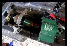
In detail: do-it-yourself repair of the 12 220 inverter from a real master for the site my.housecope.com.
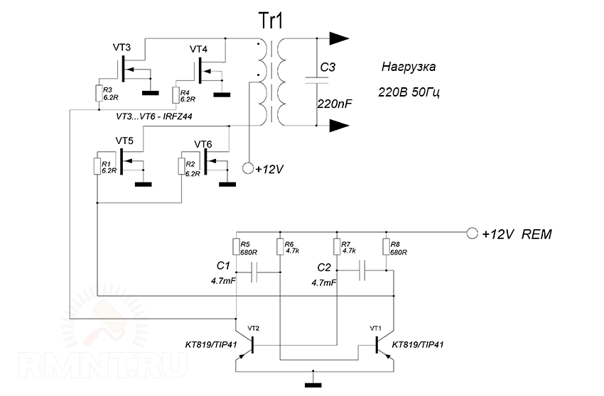
The device is built on a push-pull inverter with two powerful field-effect transistors. Any N-channel field-effect transistors with a current of 40 Amperes or more are suitable for this design, I used inexpensive IRFZ44 / 46/48 transistors, but if you need more power at the output, it is better to use more powerful IRF3205 field-effect transistors.
We wind the transformer on a ferrite ring or an E50 armored core, and it is possible on any other. The primary winding should be wound with a two-core wire with a cross section of 0.8 mm - 15 turns. If we use an armored core with two sections on the frame, the primary winding is wound in one of the sections, and the secondary one consists of 110-120 turns of 0.3-0.4 mm copper wire. At the output of the transformer, we get an alternating voltage in the range of 190-260 Volts, rectangular pulses.
The voltage converter 12 220, the circuit of which was described, can supply various loads, whose power is not more than 100 watts
Output Pulse Shape - Rectangular
A transformer in a circuit with two 7 Volt primary windings (each arm) and a 220 Volt mains winding. Almost any transformers from uninterruptible power supplies are suitable, but with a power of 300 watts or more. Primary wire diameter 2.5 mm.
In their absence, IRFZ44 transistors can be easily replaced with IRFZ40,46,48 and even more powerful ones - IRF3205, IRL3705. Transistors in the TIP41 (KT819) multivibrator circuit can be replaced with domestic KT805, KT815, KT817, etc.
Attention, the circuit has no protection at the output and input from short circuit or overload, the keys will overheat or burn out.
| Video (click to play). |
Two options for the design of the printed circuit board and a photo of the finished converter can be downloaded from the link above.
This converter is powerful enough and can be used to power a soldering iron, grinder, microwave and other devices. But do not forget that its operating frequency is not 50 Hertz.
The primary winding of the transformer is wound with 7 cores at once, with a wire with a diameter of 0.6 mm and contains 10 turns with a tap from the middle stretched along the entire ferrite ring. After winding, we insulate the winding and start winding the step-up one, with the same wire, but already 80 turns.
It is advisable to install power transistors on heat sinks. If you assemble the converter circuit correctly, then it should work immediately and does not require adjustment.
As with the previous design, the heart of the circuit is the TL494.
This is a ready-made device for a push-pull pulse converter, its full domestic analogue is 1114EU4. At the output of the circuit, high-efficiency rectifier diodes and a C-filter are used.
In the converter, I used a ferrite W-shaped core from a TPI TV transformer. All my own windings were unwound, because I rewound the secondary winding 84 turns with a 0.6 wire in enamel insulation, then a layer of insulation and go to the primary winding: 4 oblique turns of 8 0.6 leads, after winding the windings were rang and divided in half, it turned out 2 windings of 4 turns in 4 wires, I connected the beginning of one to the end of the other, that is, I made a branch from the middle, and at the end I wound the feedback winding with five turns of PEL 0.3 wire.
The voltage converter 12 220 circuit that we have considered includes a choke. It can be made by hand by winding it on a ferrite ring from a computer power supply with a diameter of 10 mm and 20 turns with PEL 2 wire.
There is also a drawing of the printed circuit board of the voltage converter circuit 12 220 volts:
And a few photos of the resulting 12-220 Volt converter:
Again the TL494 I liked paired with mosfets (This is such a modern type of field-effect transistors), this time I borrowed the transformer from an old computer power supply. When laying out the board, I took into account the conclusions of it, so be careful with your placement option.
For the manufacture of the case, I used a 0.25L can of soda, so successfully sniffed after the flight from Vladivostok, with a sharp knife we cut off the top ring and cut out the middle of it, into it I glued a circle of fiberglass with holes for a switch and a connector on it on epoxy.
To make the jar stiff, I cut out a strip from a plastic bottle the width of our body, and coated it with epoxy glue, placed it in the jar, after the glue dried, the jar became quite rigid and with insulated walls, the bottom of the jar was left clean for better thermal contact with the radiator of the transistors.
At the end of the assembly, I soldered the wires to the lid, I fixed it with hot glue, this will allow, if it becomes necessary to disassemble the voltage converter, just heating the lid with a hairdryer.
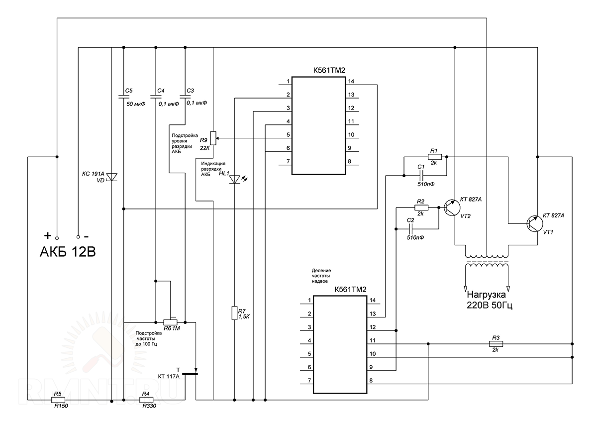
The design of the converter is designed to convert 12 volt voltage from a battery into 220 volts alternating with a frequency of 50 Hz. The idea for the circuit is borrowed from an old November 1989 issue of radio magazine.
The radio amateur design contains a master oscillator designed for a frequency of 100 Hz on a K561TM2 trigger, a frequency divider by 2 on the same microcircuit, but on the second trigger, and a transistorized power amplifier loaded with a transformer.
Transistors, taking into account the output power of the voltage converter, should be installed on radiators with a large cooling area.
The transformer can be rewound from the old TS-180 mains transformer. The mains winding can be used as a secondary winding and then windings Ia and Ib are wound.
The voltage converter assembled from the working components does not require adjustment, with the exception of the selection of the capacitor C7 with the connected load.
If you need a printed circuit board drawing made in the sprint layout program, click on the PCB drawing.
The signals from the PIC16F628A microcontroller through 470 Ohm resistances control the power transistors, forcing them to open in turn. Semi-windings of a transformer with a power of 500-1000 VA are connected to the source circuits of the field transistors. There should be 10 volts on its secondary windings. If you take a Wire with a cross section of 3 mm.kv, then the output power will be about 500 watts.
The whole design is very compact, so you can use a breadboard without etching the tracks. Archive with the firmware of the microcontroller, follow the green link just above
The converter circuit 12-220 is made on a generator that creates symmetrical pulses, following in antiphase and the output unit is implemented on field switches, into which a step-up transformer is connected to the load. On elements DD1.1 and DD1.2, a multivibrator is assembled according to the classical scheme, generating pulses with a repetition rate of 100 Hz.
To form symmetrical pulses going in antiphase, the circuit uses a D-flip-flop of the CD4013 microcircuit. It divides by two all impulses entering its input. If we have a signal going to the input with a frequency of 100Hz, then the trigger output will be only 50Hz.
Since field-effect transistors have an insulated gate, the active resistance between their channel and the gate tends to an infinitely large value. To protect the trigger outputs from overload, the circuit has two buffer elements DD1.3 and DD1.4, through which the pulses follow to the field-effect transistors.
A step-up transformer is included in the drain circuits of the transistors. To protect against self-induction of self-induction on the drains, zener diodes of increased power are connected to them. HF interference suppression is carried out by a filter on R4, C3.
The winding of the choke L1 is made by hand on a ferrite ring with a diameter of 28mm. It is wound with a PEL-2 wire 0.6 mm in one layer.The transformer is the most common network for 220 volts, but with a power of at least 100W and having two secondary windings of 9V each.
To increase the efficiency of the voltage converter and prevent severe overheating, field-effect transistors with low resistance are used in the output stage of the inverter circuit.
On DD1.1 - DD1.3, C1, R1, a rectangular pulse generator with a pulse repetition rate of 200 Hz is made. Then the pulses are fed to a frequency divider built on the elements DD2.1 - DD2.2. Therefore, at the output of the divider 6 output DD2.1, the frequency is reduced to 100Hz, and already at the 8th output DD2.2. it is 50 Hz.
The signal from the 8th output of DD1 and from the 6th output of DD2 follows to the diodes VD1 and VD2. To fully open the field-effect transistors, it is required to increase the amplitude of the signal that passes from the diodes VD1 and VD2; for this, bipolar transistors VT1 and VT2 are used in the voltage converter circuit. By means of VT3 and VT4 field-effect transistors are controlled. If no mistakes were made during the assembly of the inverter, then it starts working immediately after the power is turned on. The only thing that is recommended to do is to select the value of the resistance R1 so that the usual 50 Hz is at the output.
A transformer for a 12 220 voltage converter circuit can be made by hand. To do this, you will have to slightly redo the old power transformer from a domestic TV. We remove all windings, except for the network. Then we wind two windings with a PEL wire - 2.1 mm. Field-effect transistors are required to be installed on the radiator.
In this converter circuit, the generator generates rectangular pulses with a repetition rate of about 50 Hz with protective pauses, which exclude the simultaneous opening of field-effect transistors VT5 and VT6. When a low level appears at the output of Q1 (or Q2), the transistors VT1 and VT3 (or VT2 and VT4) will open, and the gate capacitors begin to discharge, and the transistors VT5 and VT6 are closed.
The converter itself is assembled according to the classic push-pull circuit.
If the voltage at the output of the converter exceeds the set value, the voltage across the resistor R12 will be higher than 2.5 V, and therefore the current through the DA3 stabilizer will sharply increase and a high level signal will appear at the FV input of the DA1 microcircuit.
Its outputs Q1 and Q2 will switch to the zero state and the field-effect transistors VT5 and VT6 will close, causing a decrease in the output voltage.
A current protection unit is also added to the voltage converter circuit, based on the K1 relay. If the current flowing through the winding is higher than the set value, the contacts of the reed switch K1.1 will work. At the FC input of the DA1 chip, there will be a high level and its outputs will go to a low level, causing the transistors VT5 and VT6 to close and a sharp decrease in the current consumption.
After that, DA1 will remain in a locked state. To start the converter, a voltage drop at the IN DA1 input is required, which can be achieved either by turning off the power or by short-circuiting C1. To do this, you can introduce a momentary button into the circuit, the contacts of which are soldered parallel to the capacitor.
Since the output voltage is a square wave, capacitor C8 is intended for smoothing it. The HL1 LED is required to indicate the presence of the output voltage.
The T1 transformer is made of TC-180 and can be found in the power supplies of old CRT TVs. All its secondary windings are removed, and the mains supply for a voltage of 220 V is left. It serves as the output winding of the converter. Semi-windings 1.1 and I.2 are made of PEV-2 1.8 wire, 35 turns each. The beginning of one winding is connected to the end of the other.
The relay is homemade. Its winding consists of 1-2 turns of insulated wire, designed for a current of up to 20. 30 A. The wire is wound on a reed switch housing with NO contacts.
By selecting the resistor R3, you can set the required frequency of the output voltage, and the resistor R12 - the amplitude from 215.220 V.
there are 2 inverters 12v-220v
visually all right no damage
I read that the only thing that can break there is MOSPHETS, I dropped them all and checked them with a multimeter as in the video
the first, the smaller one, when connected to 12v, loaded the source so that the source did not smoke 220v, the cooling fan does not rotate
on top he has 4 mosfets ftp10n40 2 of them are corpses judging by the check
below NCE55h12 - one of them is a corpse
after desoldering all mosfets, the fault continues to burn
the second inverter, when turned on, the fault indicator is on, the cooling fan rotates, there is 5V at the USB output. 220v is missing. after desoldering all mosfets, the fault does not burn
below it has 4 mosfets IRF3205, judging by the check, all are alive
top left to right: IRF740B is dead, IRF740A is dead, and 2 IRF740s are alive.
I tried to solder the surviving mosfets to both the first and second inverters - but neither the first nor the second worked.
what is the problem: mosfets are not interchangeable, the verification method from the video above is not perfect, or there may be other non-working parts?
As an option, evaporate and poke them (transyukas) into a voltmeter to check transistors?
In inverters, a lot of things can fail, electrolytes, diodes, anything you like, and you need to carefully consider the circuit and poke a multimeter on the voltage map.
Mosfets cannot be checked like that. they do not have a base, emitter and collector to plug into a multimeter
schemes could not be found since this is not a corporate thing, but China at its best.
the diodes checked everything - in one direction they ring in the opposite direction.
electrolytes "suspicious" on the advice from the first comment evaporated and checked with a tester as far as possible - there is not a single short circuit when dialing the resistance grows indefinitely - which indicates that they are charging
Cool mastech and the like have testers for mosfeet
The fact that the electrolyte is not in short circuit does not mean that it is in good working order, its capacity may be 1 μF, which means that it will work differently.
If you have never repaired a power supply unit that exploded into the trash, then you will not fix them either. IMHO of course, but 99.9% sure. Good luck.
Check mosfets with a tseshka, kz in any direction indicates that the fetus is dead.
check tl-ki. need an oscilloscope. if not, change it to knowingly live ones.
so-so advice, with the same success you can advise to throw
In the top photo at the top left, it looks like a bloated electrolyte - you need to look carefully.
Buy or squeeze arduin nano, build tTester M328 from it. Checks mofsets, containers, and much more. On the arduino_ru forum, you can find a circuit and firmware in the form of .ino, with them you don't even need a display - all data can be obtained via USB. A nano, even in a chipdip, costs a couple of hundred square meters, additional parts are needed for a penny.
A car voltage inverter is sometimes incredibly useful, but most of the products in stores either have a quality fault, or they do not suit in terms of power, and are not cheap at the same time. But after all, the inverter circuit consists of the simplest parts, therefore we offer instructions for assembling a voltage converter with our own hands.
The first thing to consider is the loss of electricity conversion, released in the form of heat on the keys of the circuit. On average, this value is 2–5% of the nominal power of the device, but this indicator tends to grow due to improper selection or aging of components.
The removal of heat from semiconductor elements is of key importance: transistors are very sensitive to overheating and this is expressed in the rapid degradation of the latter and, probably, their complete failure. For this reason, the base for the case should be a heat sink - an aluminum radiator.
Of the radiator profiles, a conventional "hairbrush" with a width of 80–120 mm and a length of about 300–400 mm is well suited. shields of field-effect transistors are fastened to the flat part of the profile with screws - metal spots on their back surface.But even with this, not everything is simple: there should be no electrical contact between the screens of all the transistors of the circuit, therefore the radiator and fasteners are insulated with mica films and cardboard washers, while a thermal interface is applied on both sides of the dielectric gasket with a metal-containing paste.
It is extremely important to understand why an inverter is not just a voltage transformer, and also why there is such a diverse list of such devices. First of all, remember that by connecting the transformer to a direct current source, you will not receive anything at the output: the current in the battery does not change polarity, respectively, the phenomenon of electromagnetic induction in the transformer is absent as such.
The first part of the inverter circuit is an input multivibrator that simulates the oscillations of the network for making a transformation. It is usually assembled on two bipolar transistors that can swing power switches (for example, IRFZ44, IRF1010NPBF or more powerful - IRF1404ZPBF), for which the most important parameter is the maximum permissible current. It can reach several hundred amperes, but in general, you just need to multiply the value of the current by the voltage of the battery to get an approximate number of watts of output power without taking into account losses.
The frequency of the multivibrator is not constant, calculating and stabilizing it is a waste of time. Instead, the current at the output of the transformer is converted back to constant current by means of a diode bridge. Such an inverter can be suitable for powering purely active loads - incandescent lamps or electric heaters, stoves.
On the basis of the resulting base, you can collect other circuits that differ in the frequency and purity of the output signal. The selection of components for the high-voltage part of the circuit is easier to make: the currents here are not so high, in some cases the assembly of the output multivibrator and filter can be replaced with a pair of microcircuits with the appropriate strapping. Capacitors for the load network should be electrolytic, and for circuits with a low signal level - mica.
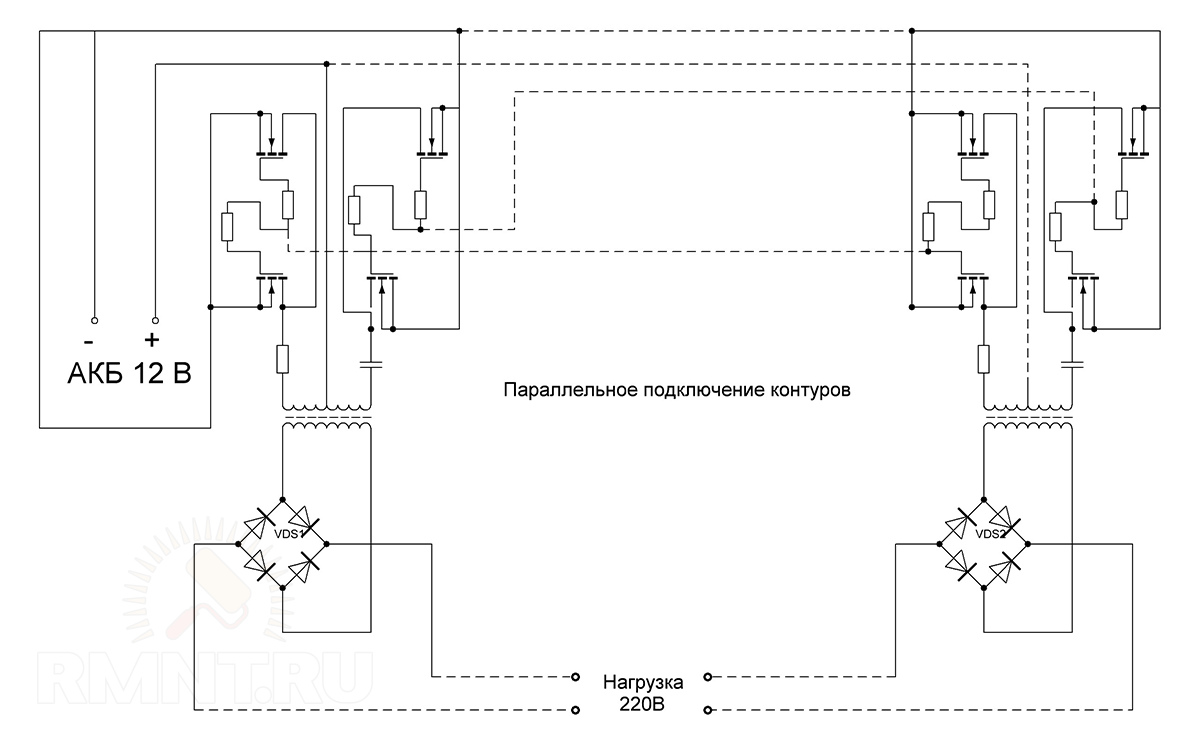
It is also worth noting that in order to increase the final power, it is not at all necessary to purchase more powerful and heat-resistant components of the primary multivibrator. The problem can be solved by increasing the number of converter circuits connected in parallel, but each of them will require its own transformer.
Voltage inverters are now used everywhere by both motorists who want to use household appliances away from home, and by residents of autonomous homes powered by solar energy. And in general, we can say that the width of the spectrum of current collectors that can be connected to it directly depends on the complexity of the converter device.
Unfortunately, a pure "sine" is present only in the main power grid, it is very, very difficult to achieve the conversion of direct current into it. But in most cases this is not required. To connect electric motors (from drills to coffee grinders), a pulsating current with a frequency of 50 to 100 hertz is sufficient without smoothing.
ESL, LED lamps and all kinds of current generators (power supplies, chargers) are more critical to the choice of frequency, since it is at 50 Hz that their operation scheme is based. In such cases, microcircuits, called a pulse generator, should be included in the secondary vibrator. They can switch a small load directly, or act as a "conductor" for a series of power switches of the inverter output circuit.
But even such a cunning plan will not work if you plan to use the inverter to provide stable power supply to networks with a mass of dissimilar consumers, including asynchronous electrical machines. Here, pure "sine" is very important and only digitally controlled frequency converters can do this.
For the assembly of the inverter, we are missing only one circuit element that performs the transformation of low voltage to high voltage. You can use transformers from power supplies of personal computers and old UPSs, their windings are just designed for the transformation of 12 / 24-250 V and vice versa, it remains only to correctly determine the conclusions.
And yet it is better to wind the transformer with your own hands, since the ferrite rings make it possible to do it yourself and with any parameters. Ferrite has excellent electromagnetic conductivity, which means that transformation losses will be minimal even if the wire is hand wound and not tight. In addition, you can easily calculate the required number of turns and the thickness of the wire using calculators available on the network.
Before winding the core ring, you need to prepare - remove the sharp edges with a file and wrap tightly with an insulator - fiberglass impregnated with epoxy glue. This is followed by the winding of the primary winding from a thick copper wire of the calculated cross-section. After dialing the required number of turns, they must be evenly distributed over the surface of the ring at equal intervals. The winding leads are connected according to the diagram and insulated with heat shrinkage.
The primary winding is covered with two layers of polyester tape, then the high-voltage secondary winding and another layer of insulation are wound. An important point - you need to wind the "secondary" in the opposite direction, otherwise the transformer will not work. Finally, a semiconductor thermal fuse must be soldered to one of the taps, the current and operating temperature of which are determined by the parameters of the secondary winding wire (the fuse case must be tightly tied to the transformer). The top of the transformer is wrapped with two layers of vinyl insulation without an adhesive backing, the end is fixed with a tie or cyanoacrylate glue.
It remains to assemble the device. Since there are not so many components in the circuit, they can be placed not on the printed circuit board, but by surface mounting with attachment to the radiator, that is, to the device body. We solder to the pin legs with a mono-core copper wire of a sufficiently large cross-section, then the junction is strengthened with 5-7 turns of thin transformer wire and a small amount of POS-61 solder. After the connection has cooled down, it is insulated with a thin heat shrink tube.
High power circuits with complex secondary circuits may require a printed circuit board with transistors in a row at the edge for free attachment to the heatsink. For the manufacture of a seal, glass fiber laminate with a foil thickness of at least 50 microns is suitable, but if the coating is thinner, reinforce the low voltage circuits with copper wire jumpers.
Making a printed circuit board at home is easy today - the Sprint-Layout program allows you to draw clipping stencils for circuits of any complexity, including for double-sided boards. The resulting image is printed by a laser printer on high-quality photo paper. Then the stencil is applied to the cleaned and defatted copper, ironed, the paper is washed off with water. The technology received the name "laser-ironing" (LUT) and is described in the network in sufficient detail.
You can etch the remains of copper with ferric chloride, electrolyte or even table salt, there are plenty of ways. After etching, the stuck toner must be washed off, the mounting holes must be drilled with a 1 mm drill and walked along all the tracks with a soldering iron (submerged arc) in order to tin the copper of the contact pads and improve the conductivity of the channels.
200A, see the 7th graph in the datasheet.
But this is closer to the truth. We look at the wahs of the field workers' diodes - at some current, the voltage dropped on them, which on the wahs of the "protective" element lies in the area of exceeding the parameters - this is a trifle and burns out, a considerable part of the converter current takes over, and the converter itself worked correctly. But, from overheating of the burnt (sih) parts it could hurt him too.
Let's wait for the author, maybe there is something new.
So I am about it. ...
Last edited by Borodach on Thu Nov 10, 2011 12:29:40 PM, edited 1 time in total.
followed by an explanation about diodes
I understand that it will fall on them even less (LH did not look)
so, how something small will burn, I still do not understand
And I did not see the transformer, the magnetic circuit, as well as the converter itself
that's why I asked for a photo
yes, and I do not insist on anything, I just assume


and there have been different cases in my practice, so I'm not surprised at anything for a long time
there was a case with a client recently
they say that the converter has discharged the battery (2 accumulators of 190 Ah in series) to 1 Volt
At night it squeaked and turned off, in the morning they could not turn it on
removed it from the battery and measured it with a tester - 1V.
brought for repair
I say, this cannot be
Yesterday I went to the object, on batteries 24.6 Volts
I say, did you charge them? NO, not charged.
They say they recovered themselves, read on the Internet, the "memory effect" is called
Well, I understood, it's useless to argue, the wife and husband (the engineer from his words) unanimously repeat - there was 1B, you saw it yourself
I arrived at work, puzzled all the way how this could be.
I told my colleagues, laughed, dispersed, there are no versions
Half an hour later, a friend comes up, I know where 1B comes from.
takes the tester and on my working battery, I look - on display 1. and it is definitely normal (battery)
it turns out that if the tester is used at the wrong limit, less than rev. voltage, it shows 1 or -1, depending on the polarity of the connection
And I forgot about it, my tester has automatic limits.
these "engineers" sometimes fool around
_________________
Don't teach me how to live, better help me financially.
To connect household appliances to the on-board electrical system of a car, an inverter is required, which can increase the voltage from 12 V to 220 V. They are in sufficient quantities on store shelves, but their price is not happy. For those who are a little familiar with electrical engineering, it is possible to assemble a 12 220 volt voltage converter with your own hands. We will analyze two simple schemes.
There are three types of converters 12-220 V. The first is that 220 V is obtained from 12 V. Such inverters are popular with motorists: through them you can connect standard devices - TVs, vacuum cleaners, etc. The reverse conversion - from 220 V to 12 - is rarely required, usually in rooms with severe operating conditions (high humidity) to ensure electrical safety. For example, in steam rooms, swimming pools or bathrooms. In order not to risk it, the standard voltage of 220 V is lowered to 12 using appropriate equipment.
There are enough voltage converters in stores
The third option is, rather, a stabilizer based on two converters. First, standard 220V is converted to 12V, then back to 220V. This double conversion allows you to have a perfect sine wave at the output. Such devices are essential for the normal operation of most electronic household appliances. In any case, when installing a gas boiler, it is strongly advised to power it through such a converter - its electronics are very sensitive to the quality of the power supply, and replacing the control board costs about half the boiler.
The circuit is simple, the parts are readily available, most of them can be removed from the computer power supply or purchased from any electronics store. The advantage of the circuit is simplicity of implementation, the disadvantage is an imperfect sinusoid at the output and a frequency higher than the standard 50 Hz. That is, devices that require power supply cannot be connected to this converter. You can directly connect not very sensitive devices to the output - incandescent lamps, iron, soldering iron, phone charger, etc.
The presented circuit in normal mode produces 1.5 A or pulls a load of 300 W, to a maximum of 2.5 A, but in this mode the transistors will noticeably warm up.
Voltage converter 12 220 V: converter circuit based on a PWM controller
The circuit is built on the popular TLT494 PWM controller. Field-effect transistors Q1 Q2 should be placed on radiators, preferably separate. When installing on one heat sink, place an insulating gasket under the transistors. Instead of the IRFZ244 shown in the diagram, you can use IRFZ46 or RFZ48 with similar characteristics.
The frequency in this 12 V to 220 V converter is set by the resistor R1 and the capacitor C2. The ratings may differ slightly from those indicated in the diagram. If you have an old non-working bezopochnik for a computer, and in it there is a working output transformer, you can put it in the circuit. If the transformer is inoperative, remove the ferrite ring from it and wind the windings with copper wire with a diameter of 0.6 mm. First, the primary winding is wound - 10 turns with an output from the middle, then, on top - 80 turns of the secondary.
As already mentioned, such a 12-220 V voltage converter can only work with a load that is insensitive to the quality of the power supply. To be able to connect more demanding devices, a rectifier is installed at the output, at the output of which the voltage is close to normal (diagram below).
A rectifier is added to improve the output characteristics.
High frequency diodes of the HER307 type are indicated in the diagram, but they can be replaced with the FR207 or FR107 series. It is advisable to select the capacities of the indicated value.
This voltage converter 12-220 V is assembled on the basis of a specialized microcircuit KR1211EU1. This is a generator of pulses that are removed from outputs 6 and 4. The pulses are antiphase, there is a small time interval between them - to exclude the simultaneous opening of both keys. The microcircuit is powered by a voltage of 9.5 V, which is set by a parametric stabilizer on a D814V zener diode.
Also in the circuit there are two field-effect transistors of increased power - IRL2505 (VT1 and VT2). They have a very low resistance of the open output channel - about 0.008 Ohm, which is comparable to the resistance of a mechanical switch. Permissible direct current - up to 104 A, pulse - up to 360 A. Similar characteristics actually allow you to get 220 V at a load of up to 400 W. It is necessary to install transistors on radiators (with a power of up to 200 W, it is possible without them).
12-220 V voltage boost converter circuit
The pulse frequency depends on the parameters of the resistor R1 and the capacitor C1, at the output capacitor C6 is installed to suppress high-frequency surges.
It is better to take the transformer ready-made. In the circuit, it turns on the other way around - the low-voltage secondary winding serves as the primary, and the voltage is removed from the high-voltage secondary.
Possible replacements in the element base:
- The Zener diode D814V indicated in the circuit can be replaced with any one that produces 8-10 V. For example, KS 182, KS 191, KS 210.
- If there are no capacitors C4 and C5 of type K50-35 for 1000 uF, you can take four 5000 uF or 4700 uF and connect them in parallel,
- Instead of an imported C3 220m capacitor, you can supply a domestic one of any type at 100-500 uF and a voltage of at least 10 V.
- Any transformer with a power from 10 W to 1000 W, but its power must be at least twice the planned load.
When installing circuits for connecting a transformer, transistors and connecting to a 12 V source, large cross-section wires must be used - the current here can reach high values (with a power of 400 W up to 40 A).
Data converter circuits are complicated even for experienced radio amateurs, so making them with your own hands is not easy at all. An example of the simplest circuit is below.
Inverter circuit 12 200 with pure sine output
In this case, it is easier to assemble such a converter from ready-made boards. How - see the video.
The next video describes how to assemble a 220 volt pure sine converter. Only the input voltage is not 12V, but 24V.
And this video just tells how you can change the input voltage, but get the required 220 V at the output.
Recently, fishermen, summer residents, hunters, beekeepers and lovers of cultural recreation in nature have used voltage converters from 12 to 220 V to illuminate tents, trailers, country houses, or as a source of emergency lighting in case of an emergency power outage in the country, in a house, garage, apartment. And for this, it is desirable to have in every home, this is a very useful and necessary device in the household.
Recently I had an idea to independently develop and assemble a compact and very economical pulse inverter from 12 to 220V, to power a 220V LED lamp, from a minimum number of radio components, capable of operating up to 14 hours from a small 7A / h 12V battery and having protection against full discharge battery. After long sleepless nights, I still managed to create an inverter that consumes only 0.5A / h and is capable of powering a super bright 220V LED lamp.
This figure shows a circuit of a single-ended pulse voltage converter from 12 to 220V. The pulse generator is assembled on the widespread NE555 microcircuit or the Soviet analogue KR1006VI1.

Pulse voltage converter from 12 to 220V with battery discharge protection
The L7809CV voltage regulator maintains a constant voltage on the microcircuit of 9V and thus the battery discharge does not affect the operating frequency of the microcircuit. Thanks to the carefully selected resistance of the resistors R2 and R3, the microcircuit produces ideally rectangular pulses, the operating mode of the microcircuit is 50% duty, and the operating frequency is 11.6 KHz. When the generator is operating in this mode, the T2 MJE13009 transistor almost does not heat up, it is enough to place it on a small radiator with a size of 30x50x10 mm.
Battery discharge protection is assembled on the T1 BD139 transistor, the P1 trimmer, the R1 resistor and the Rel1 SRD-12VDC-SL-C relay. How does protection work? After turning on the S1 switch, press the S2 button. Through the resistor R1 and the trimmer P1, power is supplied to the base of the transistor T1 and relay Rel1, the relay contacts are blocked. Trimmer resistor P1 limits the current flowing through transistor T1. As soon as the battery voltage drops to 10V, the current at the base of the T1 transistor decreases and the transistor closes, the relay contacts Rel1 open, the inverter turns off.
The protection setting consists in the correct setting of the holding current of the relay. Connect the inverter to a regulated 12V power supply. By lowering the supply voltage to 9.5 - 10V with the P1 trimming resistor, select the moment of the battery discharge protection actuation.
This figure shows a printed circuit board of a pulse voltage converter from 12 to 220V. Board size 52x24 mm. Download the board in lay format, print and transfer to PCB using laser-ironing technology. You don't need to mirror anything, everything is drawn as it should.
Printed circuit board of a pulse voltage converter from 12 to 220V with protection against battery discharge
And, now I will tell you about the most important and laborious part in manufacturing for novice radio amateurs, a pulse transformer, which you, dear friends, will have to wind on your own. In fact, there is nothing complicated in this matter, you just have to start, and then everything will go like clockwork.
And so ... you need a pulse transformer from a computer power supply or from an imported color TV. The size of each half of the "W" shaped magnetic circuit is 35x21x11mm, the size of the assembled magnetic circuit is 35x42x11mm. You got the transformer, but before you rewind, read here on how to disassemble a pulse transformer from a computer power supply or an imported color TV.
For winding a pulse transformer, I use a homemade machine, you can wind it manually, but it takes a very long time. We wind the windings in one direction, turn to turn, carefully clean the ends of the windings from the varnish with the blade of a construction knife.

In order to avoid breakdown, we insulate each layer of the wire with three layers of stationery tape. First, we wind the output winding containing 220 turns of copper wire in varnish insulation d = 0.5mm. The second one is winding a collector winding containing 50 turns of copper wire in varnish insulation d = 0.5mm. Yes, yes, that's how the first 220 turns, the second 50 turns.As practice and numerous experiments with the number of turns and the sequence of winding have shown, this is the most optimal option and, accordingly, the maximum power of the pulse voltage converter.

Yes, another important detail for a single-cycle inverter, which is this device, is to establish a non-magnetic gap between the two parts of the ferrite core 1.2 mm. Note! This figure shows two different magnetic circuits, with and without a non-magnetic gap.
Why are they so different?
This is because on the left there is a magnetic circuit from a transformer from a power supply unit of an imported color TV built according to a single-cycle circuit, and on the right is a magnetic circuit from a transformer of a computer power supply unit built according to a push-pull circuit. Therefore, if you have a transformer from an imported color TV with a non-magnetic gap of 1.2 mm, feel free to smear the halves of the magnetic circuit with glue and assemble the transformer.
And, here you will have to tinker with a transformer from a computer power supply. It is necessary to cut two circles out of thick cardboard and glue the ferrite magnetic core to the central finger, the gap between the halves should be 1.2 mm.
What kind of lamps can be connected to the inverter?
The switching voltage converter is designed to power one LED lamp Feron 230V 7W E14 6400K, it also works great with other lamps such as Saffit 230V 7W E14 6400K, Onlight 230V 7W E14 6400K and similar lamps with a power consumption of no more than 7W. In addition to the Navigator lamps, these lamps during the experiment refused to work at a frequency of 11.6 KHz, it seems they have protection. I am not advertising manufacturers of LED lamps, but simply writing about the results of my experiment.
It is strictly forbidden to connect other household electrical appliances, TVs, computers, vacuum cleaners to the inverter, because due to the high frequency of the generator, they may be damaged!
How much does this miracle inverter consume?
Due to the very low power consumption of only 0.5A / h, the inverter is capable of operating from a 12V 7A / h battery for up to 14 hours. A 12V car battery with a capacity of 60A / h will last about 120 hours of continuous operation of the voltage converter. If after assembly the inverter consumes more or less 0.5A / h, then it is necessary to select the resistance of the resistor R2.
The operating frequency of the pulse inverter is 11.6 KHz, duty is 50%, in this mode the NE555 microcircuit generates perfectly rectangular pulses.
All parts of the inverter fit easily in a small plastic junction box 75x75x45 mm.
The brightness of the lamp is sufficient for comfortable reading of an interesting book.
The pulse converter is an irreplaceable assistant for motorists. Replace a wheel, perform minor engine repairs, all this can be easily done at night or in a "shell" garage without electricity.
List of radio parts required for assembling a pulse inverter
- Chip NE555 or KR1006VI1
- Voltage stabilizer L7809CV
- Resistors R1 10K, R2 1K, R3 5.1K, R4 100R, P1 10K
- Capacitor C1 10nf, C2 1mf
- Transistors T1 BD139, T2 MJE13009, KT819
- Rel1 relay SRD-12VDS-SL-C
- Tr1 transformer from imported color TV or computer power supply with 35x42x11mm ferrite core
- Copper wire in lacquered insulation d = 0.5 mm
- LED lamp Feron 230V 7W E14 6400K, Saffit 230V 7W E14 6400K, Online 230V 7W E14 6400K and others, except for Navigator lamps
- Copper wire, stranded, double insulated 2x0.5 mm
- Cartridge E14
- Switch S1
- Button with normally open contacts S2
- Piece of PCB 52x24 mm
- Plastic junction box 75x75x45 mm
- Radiator for transistor T2 30x50x10 mm
- Connecting wires
- Straight Arms Assembly Kit
Friends, I wish you good luck and good mood! See you in new articles!
I recommend watching a video on how a self-assembled voltage converter from 12 to 220V works.
| Video (click to play). |

