In detail: do-it-yourself repair of inverter generators from a real master for the site my.housecope.com.
Gasoline, inverter generator 1.68 kW 230 V HUTER DN 2100 When the generator starts, the light (Output voltage) momentarily lights up at the output connector with a surge there is 220v, then goes into protection and the LED (Overload) is lit. In the connector (DC Output) there is 12v. No burnt-out parts were found in the electronic unit, there is no short circuit anywhere. The board with a huge heatsink is housed in a hard plastic case, filled with a dark compound, apparently “Neck is top secret”! With such a Bomb, I do it for the first time. What do you advise?
- in the ASC
The client called the service, expensive. They repair it by replacing the entire module, the repair will cost half the cost of the generator. And its price is 25,000 rubles.
Well then rip apart


(There are two faults in electronics, poor contact or none at all) proverb. Yes, that is right. I found cold soldering by touching a screwdriver to the output going somewhere inside the radiator, in the photo I marked it with a cross.
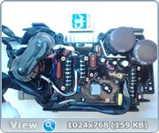
In the operation of the generator with a load of 1.5 kW, I measured the voltage where possible, see the photo.
(1) Output from 380 V alternator - phase (A)
(2) 380 V - phase (B)
(3) 380 V - phase (C)
(4) + 380V
(5) + 380V
(6) + 380V
(7) + 380 V (UCC) - inscription under the output
(8) (GND) common - label under the output
(9) + 7V
(10) + 250 V (bad soldering - went to the defense)
(11) (GND)
(12) + 250V
(13) + 250V
(14) 0V
(15) + 5 V - inscription under the output
(16) + 7V
(17) + 250V
(18) + 250V
(19) (GND)
(20) + 380 V
(21) LED (lamp control overload)
Thanks to all. All the best.
Maybe someone will come in handy. C pushed with such a misfortune. Also, a similar generator does not give out voltage. I cleaned the board with contacts 14-20. There are two GW20NC60VDs on the board and there is a thermistor between contacts 14-15, which burned out. According to the photo attached by pronnikov1. Thanks to the author.
| Video (click to play). |
All about electric generators and power plants
Everyone knows that inverter generators are much better than conventional mini-power plants in a number of indicators - they are smaller in size, which accordingly reduces their weight, work quieter, more reliable, much more fuel-efficient, while the 220V sinusoid at the generator output is much better, one might say almost flawless.
But it has become much more difficult to repair inverter generators even in Moscow, even in Magadan. The literature on repairing an inverter generator is mainly published in a foreign language, while circuit diagrams are at best depicted as functional blocks without a detailed description.
On the circuit diagrams indicated in the operating instructions, the inverter is usually indicated simply by a block or square, which makes it difficult to repair the inverter on your own at home, artisanal conditions. Experience shows that it is required to repair the electronics of an inverter generator almost at a fixed frequency: Chinese inverter generators after 200-240 hours of operation, European or Japanese ones after 2000-2400 hours of operation. Taking into account the cost of repairs in service centers, this significantly increases the average cost of 1 kW of generated electricity, and makes inverter generators not so attractive. In some cases, it is much easier for certain purposes to purchase an inexpensive gasoline generator with a synchronous generator than to develop an expensive overhaul period for an inverter generator.
The main reasons for the failure of the electronics of the inverter generator. DIY inverter generator repair
In order to increase the overhaul period as long as possible, it is necessary to understand why inverter generators fail. Then it is already possible not only to save expensive equipment from failure, but also to understand where to look for the cause of failure of the inverter electronics.
The first and most important reason for the generator failure is that the owners of power plants do not read the operating instructions and do not withstand the operation / rest and storage regime of the generator. The passport for the inverter generator indicates not only the output power of the generator, but also the operating mode of the equipment - at what ambient temperature, what load - active and reactive, can be loaded, and so on. Owners of inverter generators often prefer in practice to test the capabilities of the inverter - it will pull or not pull the load, mistakenly believing that the protection circuits themselves will throw off the load in an unacceptable mode of operation of the generator. As a result, the electrical circuit works in an extreme mode, the contacts on the board filled with compound burn out or heat up to such a temperature when the tin simply melts and spreads - as a result, either the contact disappears or a short circuit occurs in the output circuits.
The second reason, close to the first, is that manufacturers of inverter generators, especially Asian ones, deliberately overestimate the rated output power of the power plant, which is actually 30-50% less than the declared one. That is, often a Chinese inverter generator with a capacity of 3.5 kW is actually assembled from 2-2.5 kW components (especially for the motor-technical part). As a result, the owner of the power plant, loading the generator at the recommended 70% of the rated capacity, in fact rapes the power plant to the limit of its physical capabilities. As a result, the engine does not react so well to load drops, and the electronics of the inverter generator still overheats, burns, shorts and breaks down ...
Before diagnosing the reasons for the failure of the generator inverter, it is necessary to figure out what elements the electrical circuit consists of - the inverter generator board. In a simplified form, the inverter generator block can be divided into three parts PWM controller, power control switches and the output stage of the transformer.
The PWM controller generates pulses, which then form an output sine wave of 50Hz. The generated pulses are fed to transistor switches, which are increasingly being used by powerful MOSFETs with an N-channel. In this case, the voltage at the output of the transistors corresponds to the voltage of the storage battery. In order for the generated electricity to be converted into the cherished 220V 50Hz, the voltage is supplied to the output stage of the transformer.
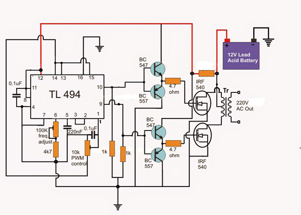
Take, for example, a typical inverter circuit based on a TL 494 PWM controller and IRF540 MOSFETs.
Check the voltage of the battery, the condition of the fuses and the electrical wires from the battery. If everything is in order, open the cover of the inverter and use a multimeter to check the correct operation of the output frequency and voltage.
Transformers are often the cause of damage to the board (block) of the inverter generator. Check the condition of the soldering, measure the windings with a multimeter for an open. As a rule, nevertheless, the transformers turn out to be tenacious, and if everything is in order with it, we turn to the main reason for the failure of the inverter generators.
About 70-80% of all troubles with electronics on the inverter generator board are associated with the failure of powerful MOS transistors and capacitors on the inverter board. In the overwhelming majority of cases, the electrical board of the inverter is filled with a thick layer of compound, while almost none of the Asian manufacturers put heatsinks on the MOS transistors for cooling. As a result, under heavy load, capacitors, diodes and transistors operate in extreme temperature conditions, which has a very, very negative effect on their service life.Chinese radioelements are not as tenacious as Japanese ones, so Asian inverters break 10 times more often than European or Japanese ones.
Any person with basic knowledge of electronics can repair an inverter generator with their own hands. The self-repair process itself is quite laborious, since the bulk of the repair will consist in carefully removing the compound from the inverter board.
Practical experience shows that the removal of the compound with chemicals is ineffective. It is much easier and more efficient to use heating and mechanical removal of the compound with a scalpel and improvised means. To warm up the compound, it is best to use a construction hair dryer, a heat gun, or an industrial hair dryer. At home, you can warm up the board in the oven at a temperature of about 100 ° C. Then free the heated inverter board from the plastic case and slowly, very carefully, remove the compound without damaging the radio elements and board tracks. When using a hairdryer, you should not use too high temperatures, while directing a stream of heated air along a tangent, ladies do not damage easily melted elements and wires.
Again, the same practice shows that when power transistors fly out, they fail together, all together, either in a break or short. Failure of transistors also entails swelling (failure) of capacitors. They will most likely also need to be replaced, at least for preventive purposes.
When replacing transistors, it is imperative to install radiators on them, even the smallest ones - everything is better than nothing. Radiators will significantly improve the temperature regime of their operation. After cleaning the compound, it is necessary to solder the dubious contacts, and cover the board itself with a thin layer of varnish. For waterproofing, you can cover the board with polyurethane foam or silicone, but it is still better not to do this, since both silicone and polyurethane foam contain aggressive components, and they will significantly worsen the heat transfer from the surface of radio components.
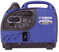
An inverter generator is called a mini-power plant that produces the most stable electric current. Such a unit is indispensable for connecting particularly sensitive electrical instruments.
An inverter electric generator is a complex technical device. Therefore, in the process of operation, failure of various elements and assemblies is almost inevitable. Routine repair of inverter generators and replacement of some parts can be done by hand.
Structurally, the inverter consists of two separate parts - the motor and the generator. Malfunctions of inverter generators can also be conditionally divided into two subgroups:
The main problems here are lack of fuel or oil, as well as a dirty air filter. In the absence of fuel or oxygen, the generator stalls or does not start.
Also, a malfunction may arise due to the lack of an ignition spark. In this case, the candles must be thoroughly cleaned and dried.
Video: how to clean an inverter generator spark plug
If the generator is not fully loaded, it is worth adjusting the carburetor.
If you have serious problems with the carburetor, speed governor or piston system, you need to contact a specialist.
First of all, the device must be de-energized. Then check the integrity of the case and disassemble the device.
The most common problems with an electric generator are:
- Poor or no contact.
- Worn or defective brushes.
- Worn or defective excitation regulator.
- If you have certain knowledge, you can replace the diode bridge and capacitor with your own hands. In the absence of the necessary knowledge, you need to turn to professionals.
Some malfunctions of inverter generators can be considered standard. They are common and you can fix most of them yourself.
The generator turns on, runs, but does not supply voltage.
This problem is very common. First of all, you need to check the health of the fuse and switch. After eliminating the found faults and in the absence of visible defects, you need to start the unit and check the voltage. If the generator is under warranty, it is worth contacting the warranty workshop.
After a certain period, the slipping and "sneezing" of the gasoline electric generator begins.
Clogged filters can be one of the reasons. Fine particles of dust and dirt get into the membranes of the cleaning filters, as a result of which the injection of fuel into the combustion chamber is impaired. This problem can be avoided by regularly cleaning the filters. If this procedure is not followed, the entire engine will eventually have to be repaired or replaced.
Video instruction for cleaning the air filter of the inverter generator:
Cleaning the fuel filter of the inverter unit
Smoke is most common when the oil level is too high. The unit, using the surplus, produces smoke. Excess smoke passes through the air filter into the chimney. In case of smoke, the first step is to check the oil level and remove the excess. You can also run the unit at full capacity to recycle it as soon as possible.
This is most often the result of prolonged installation downtime. It is worth checking if there is a sufficient amount of fuel in the tank - even if it once was, it evaporates during a long idle time. If this is the problem, just add some fuel to the tank and wait for a while. On generators with automatic start-up, the battery charge is also checked and the battery is replaced if necessary.
The current "breaks through" the body of the device.
This phenomenon occurs during long-term use of the device. It also appears when used improperly. The use of an electric generator in this case is prohibited, due to the threat to the health and life of people. Alternator rewinding is required, for which you need to contact a certified workshop.
Many troubles can be avoided by timely maintenance. This will significantly extend the life of the generator and save the owner from many problems.
Quality maintenance includes:
- Cleaning the engine from debris and dust. For hard-to-reach areas, you can use an air compressor.
- Checking the oil.
- Checking and replacing fuel during long periods of inactivity.
- Checking and replacing spark plugs, hoses.
- Check all connections for rust.
- Reliability of fastening of all parts and assemblies of the generating set.
- Replacing the air filter.
It is worth considering that carrying out any work with electrical equipment requires certain qualifications. In the absence of experience, it is worth calling the master.

Gasoline generators, even if they are made in China, very reliable with proper care... Nevertheless, during their operation, small problems can arise that can usually be quickly fixed with your own hands. Serious breakdowns with the knowledge of the owner of the device and the principle of operation of the generator will also not be able to disable it for a long time.
If you arrange possible malfunctions of the gas generator in a kind of rating, you get the following list:
- Failure or contamination of the spark plug: difficult or impossible starting, unstable operation.
- Clogged carburetor: difficult starting, excessive fuel consumption, unstable operation under constant load.
- Failure of the ignition coil: no spark, inability to start.
- Starter breakdowns: breakage, biting of the cable, destruction of the ratchet.
- Violation of valve clearances: difficult starting, increased noise during operation.
- Wear of brushes (on synchronous generators) - lack of output voltage.
- Speed governor malfunction: floating engine speed, dips when changing the load.
- Wear of the bearings of the crankshaft and the rotor of the generator - an increase in operating noise, oil leakage.
- Wear of the cylinder, piston rings - difficult starting of a cold engine, excessive oil consumption.
It does not take into account breakdowns that result from a gross violation of the rules for operating the generator: for example, seizures on the crankshaft neck due to insufficient oil level, burnout of the generator windings or voltage converter (on inverter gas generators) with frequent overloads.
In fact, malfunctions of a gasoline generator can be divided into three groups: mechanical, electrical and fuel / ignition system malfunctions.
Difficulty starting the generator, which manifested itself suddenly and not accompanied by an increase in engine noise, is a clear sign of either deviations in the operation of the carburetor (too lean or rich mixture), or a faulty ignition system (weak or intermittent spark formation). Since the diagnostics of the state of these systems is interconnected, it is combined into one section.
Remove the spark plug and inspect the carbon deposits on the electrodes.
- Dense and dry black carbon deposits - a sign of a rich mixture (the carburetor is faulty, the air filter is clogged);
- Oily black carbon - a sign of severe wear of the piston rings, oil enters the combustion chamber;
- White soot - a sign of running on a lean mixture, it is necessary to check the carburetor.
- Brick brown carbon deposits - normal for carburetor engines.
- Red, green-red carbon deposits - a consequence of working on low-quality fuel.
It is simple to check the performance of the ignition system itself because of its extreme simplicity: turn on the ignition, insert a known good spark plug into the plug cap and, putting it on the nearest metal part of the engine with its skirt, turn the recoil starter abruptly. If there is no spark, disconnect the ignition switch and the oil level sensor from the ignition coil in turn: if, when both elements are disconnected, there is still no spark, replace the ignition coil.
If the spark is present and has sufficient strength (white or blue-white), remove the spark plug after several starting attempts. A candle filled with gasoline is a sign of an over-enrichment of the mixture, a dry one is a lack of fuel.
Sometimes, after long storage, the carburetor needle and float stick and prevent gasoline from flowing inside. Several times sharply, but do not hit the float chamber lid very hard and start again.
The most common carburetor malfunction is contamination. The ingress of dirt into the air channels leads to over-enrichment of the mixture, into the fuel jets - to depletion. Dirt on the float shut-off needle leads to loss of tightness and overfilling of the float chamber, which will be immediately noticeable by the leakage of fuel from the carburetor.
Let's take a look at the carburetor maintenance using the example of a Honda GX engine installed - its design is typical of a gasoline generator.
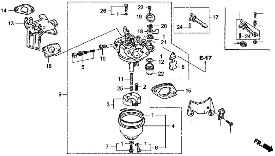
- Remove the float chamber cover (4). Wash it in gasoline or a carburetor spray cleaner - dirt and deposits accumulate at the bottom.
- Proceed in the same way with the gas valve sump (22).
- Check if the gas valve is blown in the "open" position.
- Take out the float shaft (3), take out the float and the shut-off needle (2). Blow out the channel with air.
- Blow out the fuel jet (25), emulsion tube (11) and all carburetor passages with an aerosol cleaner or compressed air.
- Remove the adjusting screw (5), blow out its channel. Then screw it in until it stops and loosen, depending on the type of air filter, by 2 (foam, paper filters) - 2.5 turns (cyclone filters).
- Assemble the carburetor.
The electrical system of gas generators is quite reliable. Most often, you can face two problems: lack of battery charging on generators with electric start or lack of voltage at the generator output.
- The lack of battery charging is a consequence of the failure of the rectifier or low-voltage winding. It is easy to check this system with your own hands: connect a 12-volt light bulb in parallel with the low-voltage winding of the generator and start it. A lit light means that the generator itself is working properly, and it is necessary to replace the rectifier.
- The absence of voltage at the generator output is most often the result of wear on the brushes. Remove them and assess the degree of wear, replace if necessary. If your generator is an inverter type, check if the voltage comes to the input of the converter by connecting a low-power 220 V lamp in parallel with it.
Video about the step-by-step repair of the gas generator
One of the routine maintenance provided by the instruction manual for gas generators is the control and adjustment, if necessary, of the valve mechanism clearances. An increase in clearances above the norm will lead to a decrease in engine power, an increase in noise during operation. The most dangerous is a decrease in the gap, since it is not audible during operation, but the pinched valves, especially the exhaust, begin to burn rapidly. As a result, the engine starts to work unstably and, when the plate is burned out, it stops starting.
Valve Adjustment Procedure pretty simple:
- Remove all components that interfere with the removal of the engine valve cover.
- Remove the spark plug.
- Remove the valve cover.
- Set the crankshaft to top dead center of the compression stroke by the mark on the flywheel (if any) or by controlling the movement of the piston through the spark plug hole. Do not confuse compression TDC (both valves are closed) with TDC issue (the outlet valve closes, the inlet valve opens).
- Loosen the locknuts of the adjusting screws and, using a flat feeler inserted between the rocker arm and the end of the valve, set the clearances by turning the screw. Typically, a clearance of 0.2 mm is adopted for the outlet valve, and 0.15 for the inlet valve (check in the operating instructions).
- Tighten the locknuts and turn the crankshaft twice to TDC. If everything is done correctly, at the next dead center both gaps will go away, after another turn they will take the set value. Increased gaps after the first revolution are a sign that they were adjusted at TDC of the exhaust stroke.
- Assemble the generator.
Manual starter malfunctions - perhaps the most common mechanical problem... Either the cable breaks, or the starter refuses to rewind it due to a broken return spring, or the ratchet does not turn the crankshaft.
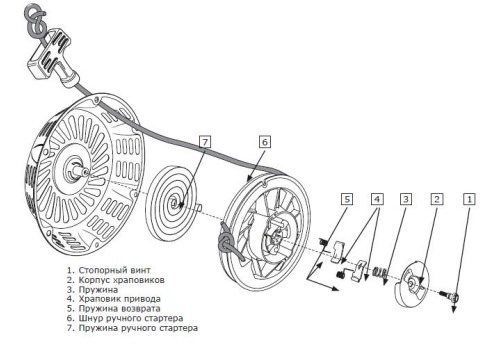
Remove the starter by unscrewing the bolts around its casing. By unscrewing the screw (1), the ratchet can be removed. Check its cams (4) and return springs (5). Then carefully remove the pulley with the spring (7). Replace a broken cable or broken spring, whichever caused the repair.
When reassembling the starter, care must be taken to ensure that the spring remains in engagement with the shroud and pulley during installation. The cable must be fully wound around the pulley. With the ratchet in place, check the cable travel and how the starter returns to its original position.
Review and repair of the Einhell STE800 gas generator
Sometimes it happens that the generator needs to be started urgently, and the recoil starter failed at that very moment. If necessary, there are several emergency start methods.
The methods listed below unsafe!
Remove the starter cover. A flywheel with a cooling impeller is located under it, which is pulled to the crankshaft by a nut. To make it spin, you can:
- With a rope wrapped around the flywheel, use it in the same way as a recoil starter rope. Note that if it snags on the fan blades, this rope will turn into a whip whip when starting the motor, so be careful.Stand so that the rope cannot get caught in your hands or head.
- Low-power engines can also be started manually: with the ignition off, turn the crankshaft several times, turning the pulley by hand in the desired direction. In this case, the gas valve must be open, and the shutter of the starting device must be closed. After that, turning on the ignition, bring the crankshaft to the compression TDC (you will feel an increase in the effort on the flywheel), and then turn the pulley with a sharp jerk so that the spark energy is enough to ignite the mixture.
- A powerful cordless drill and an extension head from the tool kit are a good replacement for a quick electric starter. Clamp the extension in the chuck, put a head of a suitable size on it and unscrew the crankshaft using the flywheel nut. True, in this way it will be possible to start only a low-power generator - for a large-volume engine, the drill torque is not enough to turn it on the compression stroke.
A number of faults, alas, are quite difficult to fix with your own hands, without sufficient qualifications: for example, a faulty inverter converter or voltage regulator can only be repaired with a good understanding of the principle of operation and circuitry of such devices. Not every owner of a gas generator will take up the engine bulkhead, although this is not as difficult as it might seem.
In this case, it is worth contacting a specialized repair shop. You can find out the coordinates of workshops in your city on the Internet or in shops selling gasoline-powered tools.
In large cities like many workshops, here are just a small part of them:
JLCPCB, 10 PP prototypes for only $ 2 and 2 days delivery!
I opened the board, kindly provided by WatchCat, the chemistry turned out to be useless, the plastic began to dissolve, with the help of a grinder and such a mother managed to pick out the board. I'll say right away, half a day work
At the output, 3 of 4 IGBT transistors are punctured, and 2 of them are short-circuited (all 3 outputs)
Input controlled rectifier, stepper control on attiny29 inverter on attiny2313
_________________
How many wonderful discoveries the spirit of enlightenment is preparing for us.
"When a society does not have a color differentiation of pants, then there is no goal!"
_________________
How many wonderful discoveries the spirit of enlightenment is preparing for us.
"When a society does not have a color differentiation of pants, then there is no goal!"
You can come up with your own, but everything is standard there, it rests only on the firmware mk))))) I have a pribluda that allows you to reset the fuses by default, but whether it will erase the firmware or not is not known)))))
A pin is a control point of some kind
For now, I'll just try to revive the board, but as soon as I buy an IGBT, a breakdown occurs, most likely due to the fact that at the moment when the engine stalls, the power supply of the output switch control circuit drops, in the end we have a breakdown. Oddly enough, I did not find anything burned out except for transistors, it seems that even the drivers are intact.
I think, put a relay to supply high voltage to the output keys and the toggle switch. accordingly, turn it on only after the engine is started, and turn it off before stopping it.
First you just have to try to read it. Phzy may not be installed. And if installed, then resetting them should erase the firmware.
Is she also revived after forcefully picking out? Surprised.
Alas - it usually dies out of the blue. It can endure repeated bullying with an electric plane, like my neighbor's, or it can die on its own when powered by a laptop and a pair of light bulbs like another neighbor's.
And if there is direct control of the keys from the MK, then this will happen with any glitch of the MK from any interference. As my Israeli friends explained to me, direct control of power keys from MK is a simple, obvious, cheap, but wrong solution.There must be a special PWM controller microcircuit, something like UC3842 or TL494, and protection against unacceptable modes must be "hardware". And MK can only interfere with the feedback signal. And so, if the MC goes to reset, the signal takes on a safe value (minimum PWM duty cycle). Then it won't die. The toggle switch will not save, since the interference in the MC arrives at an unpredictable moment in time, and the engine can also stall at any time for a bunch of different reasons.
By the way, I would not invent the inverter, but made the power plants a low-voltage output of 24V to charge the batteries, and the inverter used a ready-made Chinese DC / AC 24 to 220 even with a sine if someone really needs it, at least without a sine if, like me, I did not buy sensitive equipment to the sine.
For example a Meanwell 600 watts will do just fine. And no problems with starting currents of any refrigerators and the like - the batteries will swallow everything, unlike the internal combustion engine.
And to make a powerful converter 310 to 24 - you can use a computer power supply unit, they are now also 600 watts, but you still can't take more from this engine - the engine itself will die quickly.
He would still have to cut the operating speed by half for the purpose of a smaller and more resourceful resource, otherwise it turns under five thousand.
Power redundancy issues are still popular among power users. For these purposes, manufacturers are now mass-producing electric generators of various types and capacities. Among all the designs of such devices, a special place is given to elite models that work on the principle of generating high-quality electricity.
For this, their algorithm implements the method of inverter transformation of the main parameters of electrical signals. Due to this, they are called inverter generators.
They can be produced with various powers, but the most popular among the population are models from 800 to 3000 watts.
The source of energy for powering the engine can be:
How an inverter generator works
The design of the device, enclosed in a single body, includes:
internal combustion engine,
alternator:
inverter conversion unit;
connectors for connecting output circuits;
control and monitoring bodies for tracking technological processes.
To connect electrical appliances, a general industrial output of electricity is used through three power contacts of a conventional standard 220-volt AC outlet.
In addition to the alternating voltage, the generator provides direct current that can be used to charge various batteries, for example, used for starting a car engine. For this, the delivery set includes special clamps for connecting it to its input terminals.
The generator is equipped with protections that automatically open the supply circuit when an excessive load is applied to the output contacts. Also, protections control the technical condition of the engine, especially the achievement of a critical oil level. When it becomes insufficient to lubricate all moving parts, the engine will automatically stop from the action of the protections. To avoid this, it is necessary to monitor the oil level in the crankcase.
These generators are usually equipped with an overhead valve four-stroke engine.
The principle of operation of the inverter unit
The diagram of the interconnection of various technological processes occurring during the inversion of signals is illustrated by the figure.
The internal combustion engine spins a conventional generator that generates sinusoidal electrical energy. Its flow is directed to a rectifier bridge consisting of power diodes located on powerful cooling radiators. As a result, a ripple voltage is produced at its output.
After the bridge, a capacitor filter works, smoothing the ripple to a stable straight line, typical for DC circuits. The electrolytic capacitors are specially designed for reliable operation with voltages above 400 volts.
The reserve is made to exclude the effect of pulsating peaks of the amplitude of the operating voltage of 220 V: 220 ∙ 1.4 = 310 V. The capacitance of the capacitors is calculated according to the power of the connected load. In practice, it ranges from 470 μF and above for one capacitor.
The inverter receives a rectified stabilized direct current and generates a high-quality harmonic of the industrial frequency from it.
Various algorithms of technological processes have been developed for the operation of the inverter, but bridge circuits with a transformer have the best signal shape.
The main element that generates a sinusoidal signal is a semiconductor transistor switch, assembled on IGBT or MOSFIT elements.
For the formation of a sinusoid, the principle of creating a multiply repeating periodicity of pulse-width modulations is used. In order to realize it, each half-period of the voltage fluctuation is formed by the triggering of a certain pair of transistors in the high-frequency pulse mode with the corresponding amplitude that changes over time according to the sine law.
The final alignment of the sine wave and smoothing of the pulse peaks is done by a high-pass low-pass filter.
Thus, the inverter unit serves to convert the electricity generated by the generator windings into a stabilized value with precise metrological characteristics that provide a steady-state frequency of 50 Hz and a voltage of 220 volts.
The operation of the inverter unit is carried out by a control system that controls, through feedback, all technological processes of the generator from various states of the internal combustion engine to the shape of a sinusoid of voltage and the magnitude of the load connected to the output circuits.
In this case, the current coming from the generator windings to the conversion unit can significantly differ in frequency and signal form from the nominal values. This is the main difference between inverter models from all other designs.
The use of inverters allows you to achieve significant advantages over conventional generators:
1. They have increased efficiency due to the automatic adjustment of the engine speed during operation and the creation of an optimal mode for it according to the actual value of the load.
The more force is applied to the engine, the faster its shaft begins to rotate under conditions when the fuel consumption is strictly balanced by the control system. In traditional generators, fuel consumption is weakly dependent on the applied load.
2. Inverter generators produce an almost perfect sine wave when powering consumers under load. This high quality current is very important for the operation of sensitive digital equipment.
3. The dimensions of the elite models are compact and light in weight compared to conventional devices with the same power.
4. The reliability of inverter generators is so high that their manufacturers guarantee them twice the service life compared to simple counterparts.
Inverter generators are designed for use in three modes:
1. long-term operation under a rated load not exceeding the output power declared by the manufacturer;
2. short-term overload no more than half an hour;
3. starting the engine and reaching the operating mode of the generator, when it is required to overcome large counteracting forces of the spinning of the rotor and the capacitive load in the circuit of the power section.
In the third mode, the inverter can withstand a significant amount of opposing instantaneous power, but its run time is limited to only a few milliseconds.
To do this, you need to perform a number of operations. Let's consider their sequence on the example of one of the available models of the ER 2000 i generator. Priority of actions:
1.check the oil level, because without it, starting will not occur due to blocking by protections and a very high probability of breakdown;
2. pour fuel - without it, the engine will have nowhere to receive energy to create rotational motion;
3. open the fuel tank cap valve;
4. switch the throttle to the "Start" position;
5. set the handle of the fuel cock to the "Operation" position;
6. Start the generator by hand spinning with the cord.
At the initial start of the engine, the overload light comes on for a short time, and then for a long time - the normal mode voltage indicator, the burning of which indicates optimal operating conditions.
After starting the engine, the generator is idling and has optimal electrical parameters. The voltage and frequency shown in the picture are normal values.
After checking the idling characteristics, we connect the load to the generator, for example, using a powerful industrial hair dryer.
The power of the connected device did not change the voltage and frequency at the output of the device, and by the indication of the operating current, one can judge the power consumed by the hairdryer.
After this experiment, we connect digital computers to the DC output and see that it works reliably. When using conventional generators without an inverter unit, microprocessor digital devices fail due to the poor quality of the supply voltage.
Recommendations for safe use
Inverter generators refer to equipment using microprocessor devices and a complex electronic base. Correct observance of operating conditions, as well as careful transportation and maintenance of temperature and humidity conditions during storage are a guarantee of its long-term performance.
| Video (click to play). |
If you are constantly in the winter in an unheated garage, condensation may form on all internal parts, which will cause the failure of electronic components.

