In detail: do-it-yourself calculator repair does not work the screen from the real wizard for the site my.housecope.com.
Increase font A A A
Some of the calculator buttons stopped working.
Let's open the calculator and see what's inside. This will help us figure out why the buttons are not working.
Due to unknown circumstances, the internal board cracked (apparently brute force was used for incorrect calculations), but the copper tracks are intact. Let's remove the fee.
It is held in place by plastic rivets. They will have to be carefully cut off, after which the board can be removed.
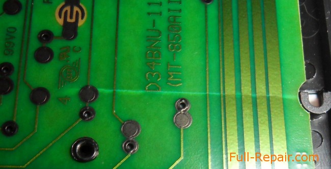
Obviously, the graphite tracks are damaged. Let's check them with a tester to make sure they are open.
We were convinced that you can start repairing.
Their big drawback is that nothing can be soldered to them. Or are there ways?
In any case, you first need to clean up the places near the damaged areas.
Conductive glue, which is, but it is not known where, will help here. Therefore, you need to build a replacement from scrap materials.
Share the article with your friends on social networks! I would be very grateful to you.


11/21/2015 at 20:00 lvl expressed:
It is also possible to precipitate copper by electrodes from copper sulfate.
11/22/2015 at 16:21 George expressed:
Yes, in theory, a good idea.
I'm not sure if the process will go fast enough due to the relatively high resistance of these tracks.
05/21/2016 at 18:08 abreu expressed:
How to cut rivets neatly?
05/21/2016 at 19:58 George expressed:
With a paper knife, it's sharp enough to cut them neatly.
05.01.2018 at 12:08 George expressed:
When I did this I did not know about the silver conductive glue. You can buy it in China and probably not only there. It could help to fix this calculator much easier and faster. I am attaching a photo.
| Video (click to play). |
and does not interfere with life, but I do not like it.
Questions:
- what is the reason for the violation? no contact?
- is it possible to repair without replacing the display?
opened it! not a single latch was damaged, although there are 6 of them in total 😀
there are no plumes, as well as conductive rubber.
everything is just like a cyst there: it is soldered, like a microcircuit
in general, the display is from the drgb-01 dosimeter, which, in particular, was used in the last bombard
there in the pictures everything is OK with the segment, because I restored it with Photoshop
in fact, at home, everything looks like this (click on the image to enlarge):
(the photo was taken so that the tracks are visible; the flare from the lamp)
from the back it looks like this:
So what do we see?
Iridescent over the output of a non-working segment - can it be air that got there during the manufacture / installation of the display, the cause of non-contact? Manufacturing defects?
Behind everything is ok.
There is an assumption that the problem may be in the K176ID2
But in general, all this is not so important, since the segment is unnecessary (its constant presence / absence does not affect the similarity of the numbers, does not entail an error in the readings).
a little pun: removing the case cover, I saw a red LED on the diagram, which lights up when the device is turned on. There is no hole on the lid to see it. So that's it. The diode is there and shines, but no one will see it until the cover is removed.
Ta-a-a-a-k. Found a way out of the situation
what have I done?
I slobber the tip of a manicure knife (which I used instead of a screwdriver) and poked it at the place indicated by the circle
before that I poked there with a slobber, - it did not help
she (saliva) seeped into this "iridescence" and everything lit up as expected
the last two questions:
- will it dry up and fail again? (here they told me that they could refuse forever 🙁 because the contacts are made of tin oxide and dissolve in water, - but I hope that the entire contact will not dissolve)
- what to poke there, so as not to refuse?
Has dried up. )
A second attempt led to the same result. It shone, and shone until it dried out, gradually dimming.
I will no longer experiment with saliva))
The question remains:
- what to poke there, so that it does not refuse and does not dry out?
Has dried up. )
A second attempt led to the same result. It shone, and shone until it dried out, gradually dimming.
I will no longer experiment with saliva))
The question remains:
- what to poke there, so that it does not refuse and does not dry out?
Conductive varnish is sold on the radio market, you can try to drip a ma-a-a-scarlet drop on (in) contact.
P.S. Not 100% sure what will help. The varnish also dries and shrinks and decreases in volume. In theory, if it gains a foothold on the contacts, it will simply stretch. It is still unclear how the deposition on glass will behave (in terms of dissolution).
You can try by taking apart some unnecessary clock or calculator (the principle of spraying on glass is the same everywhere)
I restored the indicators a couple of times, albeit without the use of varnish. In my experience, the spraying holds well, unless of course it is scratched. I repeatedly wiped (very intensively) such spraying with alcohol, everything was superb and did not wash off.
Use the same tip of the knife to drive the graphite powder into it.
PS If the LED is not parallel to the power supply, then it could serve to catch bugs.
There the hole into which you propose to “hammer in” something has a width of a fraction of a millimeter. Those. you cannot "hammer" there without destroying the display.
And the non-contact is precisely between the layers of glass, or rather, between the contact and the track to the segment.
Conductive varnish is sold on the radio market, you can try to drip a ma-a-a-scarlet drop on (in) contact.
P.S. Not 100% sure what will help. The varnish also dries and shrinks and decreases in volume. In theory, if it gains a foothold on the contacts, it will simply stretch. It is still unclear how the deposition on glass will behave (in terms of dissolution).
You can try by taking apart some unnecessary clock or calculator (the principle of spraying on glass is the same everywhere)
I restored the indicators a couple of times, albeit without the use of varnish. In my experience, the spraying holds well, unless of course it is scratched. I repeatedly wiped (very intensively) such spraying with alcohol, everything was superb and did not wash off.
Soldering is not easier =)
I was so soldered out of me that ay-ay-ay)))
My brother advised me to use some kind of marker with which they draw diagrams. What kind of if earlier the boards were varnished and etched, then there are some markers / markers with which you can draw tracks. Now this is closer to the truth - because this marker draws with a liquid, which then dries up.
Is the same conductive varnish applied there?
But my brother doesn’t have this marker, so either I’ll wait until he buys it, or I’ll have to bother myself with a visit to the radio market.
Or I take some more advice =) What is needed is a liquid, non-viscous, which can be put there on the tip of the needle, and which either does not dry out, or dries up, without ceasing to be conductive. ))
Is your TV, radio, mobile phone or kettle broken? And you want to create a new topic about this in this forum?
First of all, think about this: imagine that your father / son / brother has an appendicitis pain and you know from the symptoms that it is just appendicitis, but there is no experience of cutting it out, as well as the tool. And you turn on your computer, access the Internet on a medical site with the question: "Help to cut out appendicitis." Do you understand the absurdity of the whole situation? Even if they answer you, it is worth considering factors such as the patient's diabetes, allergies to anesthesia and other medical nuances.I think no one does this in real life and will risk trusting the life of their loved ones with advice from the Internet.
The same is in the repair of radio equipment, although of course these are all the material benefits of modern civilization and in case of unsuccessful repairs, you can always buy a new LCD TV, cell phone, iPAD or computer. And for the repair of such equipment, at least it is necessary to have the appropriate measuring (oscilloscope, multimeter, generator, etc.) and soldering equipment (hairdryer, SMD-hot tweezers, etc.), a schematic diagram, not to mention the necessary knowledge and repair experience.
Let's consider a situation if you are a beginner / advanced radio amateur soldering all sorts of electronic gizmos and having some of the necessary tools. You create an appropriate thread on the repair forum with a short description of “patient symptoms”, ie. for example “Samsung LE40R81B TV does not turn on”. So what? Yes, there can be a lot of reasons for not switching on - from malfunctions in the power system, problems with the processor or flashing firmware in the EEPROM memory.
More advanced users can find the blackened element on the board and attach a photo to the post. However, keep in mind that you are replacing this radio element with the same one - it is not yet a fact that your equipment will work. As a rule, something caused the combustion of this element and it could “pull” a couple of other elements along with it, not to mention the fact that it is quite difficult for a non-professional to find a burned-out m / s. Plus, in modern equipment, SMD radio elements are almost universally used, soldering which with an ESPN-40 soldering iron or a Chinese 60-Watt soldering iron you risk overheating the board, peeling tracks, etc. The subsequent restoration of which will be very, very problematic.
The purpose of this post is not any PR of repair shops, but I want to convey to you that sometimes self-repair can be more expensive than taking it to a professional workshop. Although, of course, this is your money and what is better or more risky is up to you.
If you nevertheless decide that you are able to independently repair the radio equipment, then when creating a post, be sure to indicate the full name of the device, modification, year of manufacture, country of origin and other detailed information. If there is a diagram, then attach it to the post or give a link to the source. Write down how long the symptoms have been manifesting, whether there were surges in the supply voltage network, whether there was a repair before that, what was done, what was checked, voltage measurements, oscillograms, etc. From a photo of a motherboard, as a rule, there is little sense, from a photo of a motherboard taken on a mobile phone there is no sense at all. Telepaths live in other forums.
Before creating a post, be sure to use the search on the forum and on the Internet. Read the relevant topics in the subsections, perhaps your problem is typical and has already been discussed. Be sure to read the article Repair strategy
The format of your post should be as follows:
Topics with the title “Help fix the Sony TV” with the content “broken” and a couple of blurred photos of the unscrewed back cover, taken with the 7th iPhone, at night, with a resolution of 8000x6000 pixels are immediately deleted. The more information you post about the breakdown, the more chances you will get a competent answer. Understand that the forum is a system of gratuitous mutual assistance in solving problems and if you are dismissive of writing your post and do not follow the above tips, then the answers to it will be appropriate, if anyone wants to answer at all. Also note that no one should answer instantly or within a day, say, no need to write after 2 hours “That no one can help”, etc. In this case, the topic will be deleted immediately.
You should make every effort to find a breakdown on your own before you get stumped and decide to go to the forum.If you outline the entire process of finding a breakdown in your topic, then the chance of getting help from a highly qualified specialist will be very great.
If you decide to take your broken equipment to the nearest workshop, but do not know where, then perhaps our online cartographic service will help you: workshops on the map (on the left, press all buttons except “Workshops”). You can leave and view user reviews for workshops.
For repairmen and workshops: you can add your services to the map. Find your object on the map from the satellite and click on it with the left mouse button. In the field “Object type:” do not forget to change to “Equipment repair”. Adding is absolutely free! All objects are checked and moderated. A discussion of the service is here.
Everything I do at work: computers, automation, controllers, programming, etc.
Amazing nearby!
If they told me in all seriousness that the earth is flat, I would be as surprised as Oleg said that the solar-powered calculator also uses the most ordinary iron battery.
Oleg said that one day his faithful friend and assistant, an accounting calculator like Citizen SDC-888, stopped working. Having opened the case, Oleg was amazed at what he saw inside the calculator. According to him, there was an iron tablet battery installed in the calculator.
The solar battery was simply not connected to the calculator board, from which he concluded that this solar battery was just a props. The internal installation of Oleg's calculator was also surprised - the boards were casually tied to each other with adhesive tape.
Oleg replaced the battery in his calculator and it magically started working again.
I have the same calculator, Oleg told his story because he saw the same device with me.
I was not used to taking my word for it, so right there, under Oleg, I decided to check the veracity of the cruel accusations myself.
Disassembled my Citizen and looked inside.
Here's what I saw there.
I was very surprised by this post.
This calculator is NOT a “solar powered calculator”!
It clearly reads “2 POWER”, i.e. powered by solar cell AND BATTERY.
In addition, measure the voltage on the solar cell when it is turned towards the table with the work surface. to put it mildly, wrong.
>> Maybe in order to work at dusk.
It is for this!

Eugene, you are right, there really is an inscription “2 Power”.
Your observation does you credit. For example, I drew attention to this inscription only after your words.
I can bet that at least 95 out of 100 users of this calculator, like me once, sincerely consider this calculator to be exactly and only solar because of carelessness and the presence of a solar battery.
—
measure the voltage on the solar cell when it is turned towards the table with the work surface. to put it mildly, wrong.
—
From what? The goal is achieved - I saw the voltage on the element, then the element works, which was required to be proved. Everyone understands that when orienting to the sun, the voltage will be higher.
But in this case, I would not have been able to photograph the experience without outside help.
I apologize for the stupid question, but what are the indicators of a solar battery?
I will state the question
I have a socket somewhere 8cm high by 3cm wide
in the sun, the multimeter shows 6v, but the 3 volt bulb does not even glow
That is, there is no current at all, so the question is what current the solar panel generates, you can measure it from your own calculators, at least I know how much on yours, so I can understand approximately how many on mine) I will be very grateful)
If you have patience until Monday, I will definitely measure it.
1.5 volts on a multimeter from a fluorescent light bulb,
The strength of the current is measured in amperes. Turn on the calculator, enter 8s on the keyboard on the full screen, take out the built-in battery.Parallel to the solar battery, that is, parallel to the consumer (as in the photo of the author of the topic), we measure the current strength. If you don't turn on the calculator, you can burn the ammeter. You will not burn at such currents, but if you do this, for example, on a car battery (measure not on the consumer, but on the battery), it will burn
If you need to know the current strength, you need to measure it sequentially.
And yet, there is a specific benefit from the post 🙂 Nowhere on the calculator itself, and even inside it, the type of battery is not indicated. As in my case, when I got the calculator for use with the battery already removed, it would be very difficult to find its type without this post.
I have this particular calculator. It stopped working. Where can I buy and replace this battery? Where can I get it repaired? I live in Moscow on Babushkinskaya, Elena.
Tablets are sold in any supermarket
In any computer supermarket like Technopolis, Foxtrot or whatever they call them in Russia.
I am such a good fellow - I opened the calculator myself and saw this battery. In the Technosila store - no, in MVideo - no. Where to "go" now? Muscovites, please respond. Elena.
It turned out to be easier for me - the battery is under the iron plate. I turned it back so that the contact was good and voila - everything worked. Since I checked the battery on another, it worked. Apparently the contacts oxidize over time - it is better to clean and bend it.
Elena, go to the store selling radio components or order on e-bay))
Now I would look for tablets in large stores.
My calculator has a slightly different board and battery mount. The solar panel is present and connected. The battery costs GP189. The photo shows the board.
Guys ! You don't know that the Chinese are shameless of us all
make a fool.
These batteries can be purchased at watch repair kiosks.
Indeed, the overwhelming majority of calculators have a battery. But you should not worry, you can replace it with any other one that is suitable in size. Well, and a suitable price, of course. In some retail outlets, batteries are more expensive than calculators themselves. It's funny that cheap calculators wear out buttons faster than batteries fail.
Pure solar calculators are easy to distinguish by their thickness, up to 3 mm. But there are not many of them.
if the calculator is not new, then the presence of a solar battery can be checked by dialing 8 to fill the scale and covering the solar panel with your finger. If the numbers fade, then the solar is working.
I read your article. Exactly the same calculator as the author has. Did not work. After replacing the battery, everything worked.
Such batteries are sold at any point in the market that sells batteries. The type (what is written on it) is not important, the main thing is that it fits in size.
Thanks to the author of the article and the commentators!
It turned out that the SDC 8860 calculator is also 2 POWER! What, by the way, is reported on the front panel (but who reads what is written there))), because we do not like to study materiel)
Hope the calculator will work after replacing the swollen GPA76 battery!
Tell me which battery is in the citizen fs-80 calculator
1) Batteries for calculators are sold in places that repair watches, as well as small electrical goods.
2) The calculator battery is dead. I threw it out. I switched on the desk lamp, the calculator works great.
If you want, send me the scheme by mail, I will post.
it's easier to buy a new battery for 10 rubles
Is it possible to charge a tablet from a solar battery? So to speak, external solar charging?
The Chinese sell such solar panels, aliexpress is full of them.
I CANNOT REMOVE the back cover, I unscrewed the screws
I took it off somehow, thanks for the article, my SDC-414N was expensive, it was a pity to throw it away, the wiring to the solar battery is soldered, but it does not work, I hope to replace the battery
A “solar cell” is installed to recharge the internal battery.So, if the calculator is exposed to the light all the time, then the battery life will be significantly lengthened. If stored in a dark place, the battery life is much shorter.
Where have you, Mr. Anonymous, saw that the batteries were charged! Even if there was a battery, the current from the solar panel would still not be enough.
I was struck by the surprise of the author and his bewilderment, they say, “how was it even allowed, so that there was also a battery inside ?!”. Like a schoolboy.
I took out the battery from mine, continued to work but a little dimmer. I have never disassembled it. The battery was inserted under the cover.
The battery is needed so that it does not extinguish when there is no sun, electricity is accumulated in it.
In general, it was you who surprised me that you were surprised at this thing. You seem to be living in the Stone Age, and you won't even surprise a schoolchild with that. First, the calculator clearly states that it is powered by two power supplies. Secondly, the metal battery is the battery, and the solar panel is the charger. What is not clear here
This, for example, is not clear: "a metal battery is a rechargeable battery." Every schoolchild knows that a battery differs from a battery in the possibility of multiple charging. How you put the GP189 battery into the batteries is completely incomprehensible.
People. You have to do what not dick.
Just renovated 2 calculators. Moreover, I threw out the old battery and soldered the usual AA for 1.5v, and in the second I had to wrestle with AAA, tk. the body is slightly smaller. But all the same, it turned out cheaper and will last for longer, tk. the capacity of such fingerlings is clearly higher than tablet ones. Good luck!
This calculator worked for me for ten years. A regular battery wouldn't last that long. And even when his insides crawled out of him from old age, he tried to give out something to the last. However, nothing lasts forever, and my comrade-in-arms rested in peace on the shelf. I miss him as hell.
Service centers and calculator repair shops
Moscow, st. Vorontsovskaya, 35B building 1 view on the map
Canon warranty repair, SHARP
- one-time repair of copiers and printers, both at the customer's site and in the conditions of our service center; contractual service; - sale of duplicating equipment, ...
Moscow, 2nd Irtyshsky pr-d, 4-1 see on the map
PHILIPS warranty repair
Moscow, 2nd Kotlyakovsky lane, 1/6 look on the map
PHILIPS warranty repair
- - delivery of the calculator for repair by the service center
- - on-site repair of the calculator at home or in the office
- - service of replacement of consumables
- - services for the installation and configuration of equipment
- - sale of spare parts for calculator repair.
 - delivery of the calculator for repair by the service center
 - on-site repair of the calculator at home or in the office
 - service of replacement of consumables
 - services for the installation and configuration of equipment
 - sale of spare parts for calculator repair.
To install or configure the purchased equipment, you can use the services of specialists from authorized organizations (authorized service center), who will carry out all the necessary work for the further operation of the calculator. The addresses of all service centers on the map of Moscow are given at the top of the page. If there is no service center at the indicated address or is located at a different address, please let us know.
They offer me one raretetic that I want to have for a long time. But here's the trouble - on its LCD (4x8 symbolic 7x5 symbols + additional icons) some columns do not work. Finding a new indicator is unrealistic due to the antiquity and rarity of the device. The construct is a flat ribbon cable on which the controller's microcircuit is connected directly to the glass; all voltage dividers are placed outside the connector and are soldered on the device board. A typical controller - judging by the interface. But the non-standard glass 3x4 cm itself is connected along one edge with a train. Is it realistic to restore (cliffs in the center).
Likewise https://my.housecope.com/wp-content/uploads/ext/1366/repair/11178/
More recently, the problem has been resolved by replacing the indicator.
I agree that it would be a solution to the problem - but the probability of finding the same indicator tends to zero, there may have been 5-10 thousand of these devices in history and since 1996 how many have survived to us, and they have never been supplied to the Russian Federation. Chances are scanty that the same indicator could be used in the equally terribly ancient DAMS cell phones. but they are rare in themselves.
Around the mid-2000s, as far as can be judged, a “new” technology was introduced to connect glass LCD indicators through the adhesive end of a flat thin ribbon. The technology is extremely unsuccessful - after six months or a year, the train was almost guaranteed to peel off, and nothing could stick it. Household adhesives were not suitable as they did not allow current to pass through. I tried to simply press the cable to the glass with a rigid crossbar, at the ends of which there are screws. It turned out badly, some of the segments in the middle of the train were not pressed tightly, the lining of the rubber pad did not help or did not help for long, before the elastic dries. In this manner, I had to throw out several cordless phones in a row, the last one a year ago. I do not know if this problem is solved with the current ones or everything is still the same.
somehow, for fun, I pasted such a loop on the hardener (there was a test of the technologies described in the net and the literature did not work; glue applied droplets of glue-liquid rubber, followed by attaching through the strip of thermoresin (from the gaskets of the microcircuits) to the HOT IRON (glue dripped onto the glass where there are no tracks
oddly enough it was fucking and it worked I don’t know how long did it take, kalk gave it to someone and didn’t follow the fate
in general, the method is only for unique devices-kontaktol-expensive but works
this method is simpler but without guarantees
It seems to me that some factory technologies cannot be repeated on their knees. Need to try. They will not be shot. 
The device was released in 1997. It is unique, of course - one of the first (more precisely, the third) in its class - it gets to me - I'll tell you. They just want money for the device, and it will be a shame if you cannot reanimate it to a state of use. Again, death is full of an indicator - this is also sad.
How much is the price of the issue? How much money do they want? Recently I got my hands on a unique camera from the early 20th century. So it costs 70-100 bucks on "ebay". Funny.
Maybe you are fooled and want too much for electronic trash?
Flexible tape bundles can be well pressed against whole flat molds on a glass LCD with a strip of foam rubber, resting, for example, against the closing lid. The principle works reliably when repairing calculators with an LCD display.
And here's how to restore the petals themselves. here it is more likely to use tin oxide for precipitation ..
we have several Citizen accounting calculators, there are a couple that work, but some segments are not included on the lcd screen.
how is this treated?


Disassembly can help, wiping the contacts on the board with a washing rubber band, where the display adjoins through conductive rubber. Or it may not help.
I still have casio, the same problem. sometimes it will lie down, and everything is in order.
maybe the train deteriorates over time 
In response to:
we have several Citizen accounting calculators, there are a couple that work, but some segments are not included on the lcd screen.
how is this treated?
Offtopic:
Announcement: a reputable company that has been working in the market for more than ten years will rent a hole punch.

Tell me how to glue the calculator screen cable? / pls /
Thank you guys!
I have a scientific CASIO. From the side of the board, a screen cable (gray with black tracks) began to leave. Moreover, several of my friends also had this problem. As you advised, I cut off the train, removed with nails, zero and white spirit the remnants of the old train.I put the new cut in place of the old one and ironed it with the edge of the iron (3-point regulator). It worked right away. Pleased with myself scary.
Probably, it was possible to fix the problem without cutting, simply by ironing, but my case - see below
P.S. Before that I tried with a soldering iron, as advised. I groped for a contact so that a sign would work on the screen, and pressed it. But the soldering iron turned out to be too hot, and it's a lot of hemorrhoids. As a result, I generally shortened the contacts with the remnants of tin or something else, and the screen was cut off. I had to do the same as described above.
Status: offline
Hello dear girls!
The online clothing store wants to offer you a large selection of dresses for 2016-2017 for the summer season:
We have a joint purchase with good conditions:
And you can also buy any product in bulk at a low price:
- Delivery to anywhere in Russia.
- Various payment methods.
- Preliminary fitting before purchasing the product.
- Purchase returns.
| Video (click to play). |
We will be glad to cooperate.
Warm summer and pleasant shopping!


