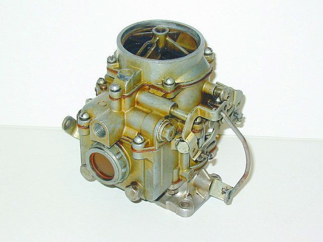
In detail: do-it-yourself repair of a carburetor to 126 gu from a real master for the site my.housecope.com.
The times of the k126 carburetor began in the 1960s. K126 carburetors were installed on domestic cars and light trucks. The k126 carburetor is still used in the vastness of the former Soviet Union and can still be easily purchased at auto parts stores.
The carburetor K 126 has many modifications, below I will give the information that I managed to find:
They differ in tops, parts, soles, diffusers, calibrations, etc.
Consider the device of the carburetor k126. The k126n carburetor has a similar structure. Carburetor K-126 - emulsion, two-chamber, with a falling flow, with sequential opening of the throttle valves and a balanced float chamber.
The carburetor has two mixing chambers: primary and secondary. The primary chamber operates in all engine modes. The secondary chamber is activated under heavy load (after about 2/3 of the throttle stroke of the primary chamber).
To ensure uninterrupted operation of the engine in all modes, the carburetor has the following metering devices: a primary chamber cold run system, a secondary chamber transition system, main metering systems of the primary and secondary chambers, an economizer system, a cold engine start system and an accelerator pump system. All elements of dosing systems are located in the body of the float chamber, its cover and the body of the mixing chambers. The body and cover of the float chamber are cast from zinc alloy TsAM-4-1. The mixing chamber body is cast from AL-9 aluminum alloy. Sealing cardboard gaskets are installed between the body of the float chamber, its cover and the body of the mixing chambers.
| Video (click to play). |
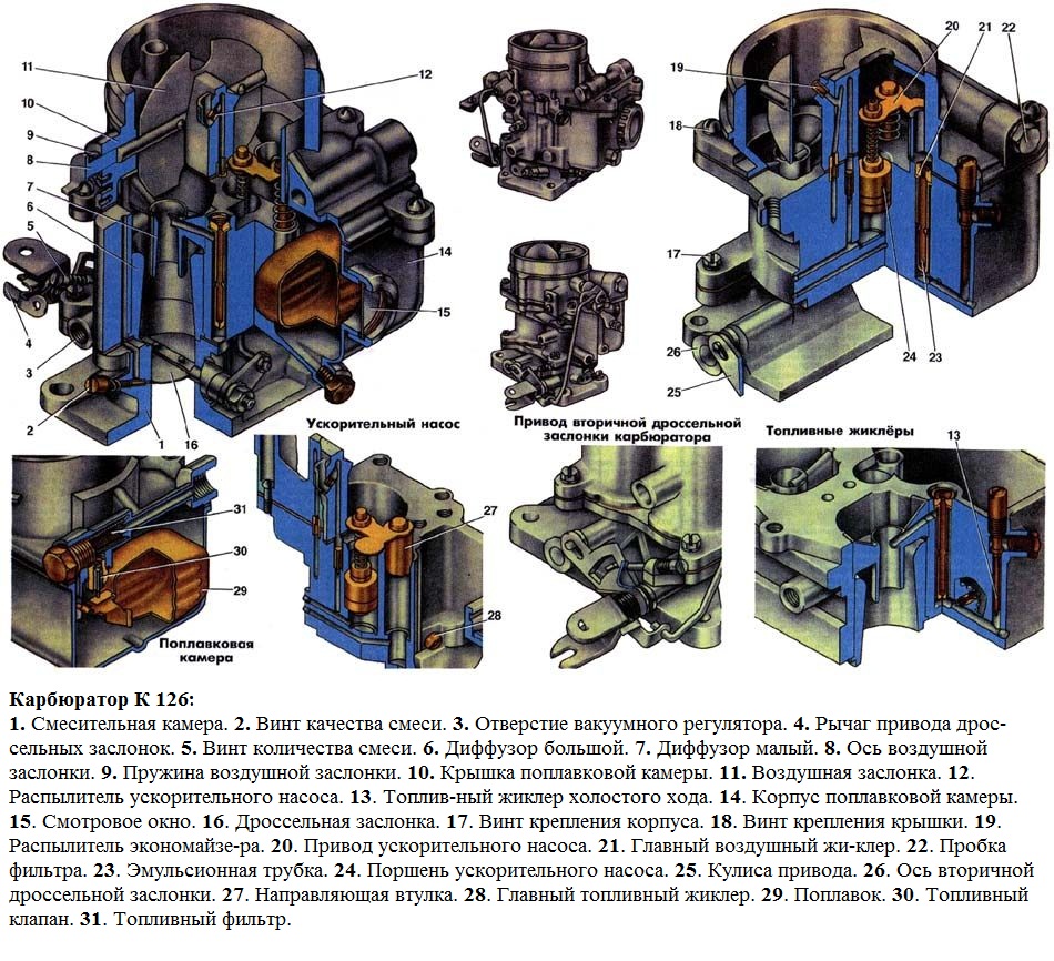
Carburetor device K-126
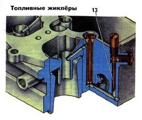
The body of the float chamber contains: two large 6 and two small diffusers 7, two main fuel jets 28, two air brake jets 21 of the main metering systems, two emulsion tubes 23 located in the wells, a fuel 13 and air jets of the idle system, an economizer and a guide sleeve 27, an accelerator pump 24 with delivery and non-return valves.
The nozzles of the main metering systems are led out into the small diffusers of the primary and secondary chambers. The diffusers are pressed into the body of the float chamber. In the body of the float chamber there is a window 15 for monitoring the fuel level and the operation of the float mechanism.
All channels of the jets are fitted with plugs to provide access to them without disassembling the carburetor. The idle fuel jet can be turned out from the outside, for which its housing is brought out through the cover up to the outside.
In the cover of the float chamber there is an air damper 11 with a semiautomatic drive. The air damper drive is connected to the primary chamber throttle valve axis by a system of levers and rods, which, when starting a cold engine, open the throttle valve to the angle necessary to maintain the starting engine speed. The secondary throttle valve is then tightly closed.
This system consists of an air damper drive lever, which acts with one arm on the choke axle lever, and with the other, through the rod to the idle lever, which, turning, presses the primary chamber damper and opens it.
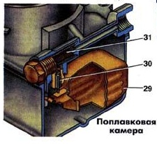
A float mechanism is mounted in the carburetor cover, which consists of a float suspended on an axle and a fuel supply valve 30. The carburetor float is made of 0.2 mm brass sheet. The fuel supply valve is collapsible; it consists of a body and a shut-off needle. Valve seat diameter 2.2 mm. The cone of the needle has a special sealing washer made of a fluoride rubber compound.
The fuel entering the float chamber passes through the 31 mesh filter.
In the housing of the mixing chambers there are two throttle valves 16 of the primary chamber and the secondary chamber, an adjusting screw 2 of the idling system, a toxicity screw, channels of the idle system, which serve to ensure the coordinated operation of the idle system and the main dosing system of the primary chamber, opening 3 of the vacuum supply to a vacuum ignition timing regulator; and a secondary chamber transition system.
The main carburetor systems operate on the principle of pneumatic (air) fuel braking. The economizer system works without braking like a simple carburetor. The idle, booster pump and cold start systems are available only in the primary chamber of the carburetor. The economizer system has a separate spray nozzle 19, which is led out into the air branch pipe of the secondary chamber. The secondary chamber is equipped with an idle transition system.
The idling system of the carburetor consists of a fuel jet 13, an air jet and two holes in the primary mixing chamber (upper and lower). The lower hole is equipped with a screw 2 for adjusting the composition of the combustible mixture. The idle fuel jet is located below the fuel level and is included after the primary chamber main jet.
Fuel jets of the carburetor k126
The fuel is emulsified with an air jet. The required performance of the system is achieved by the idle fuel jet, the air brake jet, and the size and location of the vias in the primary mixing chamber.
The main metering system of each chamber consists of large and small diffusers, emulsified tubes, main fuel jets and main air jets. The main air jet 21 controls the flow of air into the emulsion tube 23 located in the emulsion well. The emulsion tube has special holes designed to obtain the required performance characteristics of the system.
The idle system and the main metering system of the primary chamber provide the required fuel consumption at all main engine operating modes.
The economizer system consists of a guide sleeve 27, a valve 23 and an atomizer 19. The economizer system is put into operation at 5-7 until the throttle valve of the secondary chamber is fully open.
It should be noted that, in addition to the economizer system, the main metering systems of both chambers operate at full load and very little fuel continues to flow through the idle system.
The accelerating pump system consists of a piston 24, a drive mechanism 20 for the inlet and discharge (outlet) valves, and a spray nozzle 12, which is brought out into the air nozzle of the primary chamber. The system is driven from the primary chamber throttle axis and works when the vehicle is accelerating.
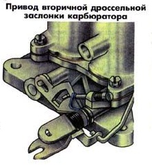
On the axis of the throttle valve of the primary chamber, the drive lever 4 is rigidly fixed. The link of the link 25 is also rigidly fixed on the axis. The link is freely installed on the axis of the damper 16 and has two grooves. In the first of them, the leash moves, and in the second, the pin with the roller of the lever 26 of the drive shaft 8 of the secondary damper fixed on it.
K126 second chamber throttle actuator
The flaps are held in the closed position by springs attached to the primary chamber axis and the secondary chamber axis.The rocker 25 also constantly tends to close the shutter of the secondary chamber, since it is acted upon by a return spring attached to the axis of the primary chamber.
When the lever 4 drives the axis of the primary chamber, the leash of the lever of the primary chamber first moves freely in the groove of the link 25 (thus only the damper of the primary chamber is opened), and after about 2/3 of its travel, the leash begins to rotate it. The rocker 25 of the secondary flap drive opens the secondary throttle valve. When the gas is released, the springs return the entire lever system to its original position.
Carburetors K-126 are very simple in design, moderately reliable and require minimal maintenance if used correctly. Most malfunctions occur either after unskilled intervention in the adjustment or in the case of clogging of the metering elements with solid particles. Among the types of maintenance, the most common are flushing, adjusting the fuel level in the float chamber, checking the operation of the accelerator pump, adjusting the starting system and the idle system.
Consider adjusting the carburetor to 126 using the example of K 126GU.
K126 fuel level adjustment
Check the fuel level with the engine off of a vehicle installed on a horizontal platform. When pumping fuel using a manual pump drive, the fuel level in the carburetor float chamber should be within the range marked by marks (tides) "a" on the walls of the inspection window. If the level deviates from the specified limits, make adjustments by removing the cover of the float chamber. Adjust the level by bending the tongue 3 (see fig.). At the same time bending the stopper 2, set the needle stroke 5 of the fuel supply valve to 1.2 - 1.5 mm. After adjusting, check the fuel level again and, if necessary, make the adjustment again. Considering that during operation, due to wear of the float mechanism, the fuel level gradually rises, set it when adjusting to the lower limit. In this case, the fuel level will be within acceptable limits for a longer time.
Note. When adjusting the fuel level in the carburetor float chamber, do not bend the float tab by pressing the float, but bend it with a screwdriver or pliers.
Adjustment of the minimum idle speed is carried out in the following sequence:
- we warm up the engine to operating temperature;
- turn screw 15 all the way, but not tight, and then unscrew it 1.5 turns;
- start up the engine and with the stop screw 43 of the throttle valve set a stable crankshaft rotation speed of 550 - 650 rpm;
Checking the adjustment results is carried out by abruptly pressing the gas pedal, the engine should not stall, there is a smooth drop in revolutions
The screw 15 of the toxicity limiter adjusts the limit value of carbon monoxide (if equipped with a gas analyzer).
It is possible to adjust the idling system of the carburetor k126 without a gas analyzer.
This is how this procedure is described in the book by N.N. Tikhomirov. "Carburetors K-126, K-135":
In the absence of a gas analyzer, almost the same control accuracy can be achieved using only a tachometer or even by ear. To do this, on a warm engine and with a constant position of the "quantity" screw, find, as described above, such a position of the "quality" screws, which ensures the maximum engine speed. Now use the "quantity" screw to set the speed to about 650 rpm "1. Check with the "quality" screws whether this frequency is the maximum for the new position of the "quantity" screw.If not, repeat the whole cycle again to achieve the required ratio: the quality of the mixture ensures the maximum possible speed, and the number of revolutions is about 650 min. ”1. Remember that the "quality" screws must be rotated synchronously.
After that, without touching the “quantity” screw, tighten the “quality” screws so much that the rotational speed decreases by 50 minutes ”1, i.e. to the regulated value. In most cases, this adjustment meets all the requirements of GOST. Adjustment in this way is convenient in that it does not require special equipment, and can be carried out every time the need arises, including for diagnosing the current state of the power supply system.
In case of inconsistency of CO and CH emissions with the GOST standards at an increased speed of rotation (Nпов ", = 2000 * 100 min" ’), the impact on the main adjusting screws will no longer help. It is necessary to check if the air jets of the main metering system are dirty, if the main fuel jets are enlarged or if the level of fuel in the float chamber is too high.
The K 126 carburetor, like all other carburetors, has its weak points. A very weak point in the carburetor k126 is the attachment of the lower part of the carburetor to the middle one, in this place the fasteners are over time exposed to heat from the engine side and in these places, with a strong constriction of the carburetor fastening, and at an increased operating temperature of the engine, the fastenings of the carburetor halves were deformed, as as a consequence, a gap appears between the lower middle part of the k126 carburetor, the transition channels of the idle system begin to suck in air and it becomes almost impossible to adjust the idle speed, this applies to almost all carburetors of the k 126 family.
Checking the plane of the carburetor flange
You can check the flange plane using a straight ruler, as shown in the figure (Solex carburetor is shown, the principle is the same). To eliminate this problem it is necessary to disassemble the carburetor completely, remove the large diffusers from the middle part, and grind both halves, replace the intermediate spacers with new ones and assemble the carburetor. After the engine has warmed up to operating temperature, adjust the idle speed and mixture quality.
A feature of the K-126 carburetors is that the adjustment is not particularly difficult and does not require the cost of tools and special tools. It is for this reason that the production of carburetor k126gm cars continues, which are used under difficult conditions, far from the services of a car service. Compliance with the frequency of maintenance will make it possible to operate the car for a long time without critical breakdowns.
Video about the device and repair of the carburetor k126.
It would seem that the era of carburetor cars has passed a long time ago, but no, these cars still roam on our roads today and at the same time "feel" quite confidently. One of these machines is the UAZ-452, better known by the nicknames "Loaf", "Baton", "Tablet".
"Loaves" from the first day of their production were equipped with carburetors of the K-126, K-129 type and their modifications. This continued until 1985, when the car was completely modernized. Along with the new, more powerful engines, the K-131 and K-151 carburetors, as well as their numerous improved versions, began to be installed on the UAZ-452.
But the simplest, most reliable and maintainable of them turned out to be the K-126 carburetor, which, among other things, was the most economical. If the engine with K-131 and K-151 consumed on average 15-17 liters of gasoline per hundred kilometers, then the K-126 made it possible to save 3-4 liters. All the latest models of UAZ-452 carburetors are interchangeable, except that the K-126 requires an additional gasket between its "fifth" and the intake pipe.
The K-126 line is a generation of carburetors produced by the Lenkars plant (Leningrad), which later became the famous Pekar.The first models of two-chamber K-126 were manufactured in 1964 for the new ZMZ-53 engine, which replaced the obsolete GAZ-51.
The carburetor consists of three main elements:
- throttle assembly (mixing chamber bodies);
- float chamber;
- cover.
K-126G has two chambers for mixing fuel with air. The first one works in all modes, and the second one only at high loads, when the first throttle opens more than 2/3 of the stroke.
An air damper with a drive mechanism and a float mechanism are installed in the cover of the device. The float chamber contains diffusers, fuel and air jets, an accelerating pump, and emulsion tubes. The throttle assembly contains dampers (one in each chamber) and adjusting screws. In addition, there is a transition hole for the idle system, as well as channels for air and fuel.
The K-126G design includes the following systems:
- cold start;
- idle move;
- dosage.
It also has such units and mechanisms:
- float mechanism (float, float axis, needle valve);
- economizer (valve, sprayer, drive mechanism);
- accelerator pump (piston, inlet and outlet valves, drive mechanism).
- Accelerator pump.
- Main air jet of the secondary chamber.
- Small diffuser of the secondary chamber.
- Balancing channel.
- Economizer sprayer.
- Air damper.
- Accelerator pump sprayer.
- Discharge (outlet) valve.
- Air damper rocker mechanism.
- Idle air jet.
- Small diffuser of the primary chamber.
- Main air jet of the primary chamber.
- Fuel valve.
- Fuel filter.
- Float.
- Observation window.
- Drain plug.
- The main fuel jet of the primary chamber.
- Primary chamber emulsion tube.
- Throttle valve drive lever.
- Primary chamber throttle valve.
- Idling via.
- Mix quality adjustment screw.
- Idling fuel jet.
- Secondary chamber throttle.
- Large diffuser.
- Secondary chamber emulsion tube.
- The main fuel jet of the secondary chamber.
- Non-return (inlet) valve.
Like any other mechanical device, the carburetor cannot run smoothly all the time. The reasons for this may be:
- clogging of jets and channels;
- wear of gaskets or seals;
- violation of the regulation of systems and mechanisms.
Symptoms that the carburetor is in emergency mode include:
- unstable idle (floating speed);
- impossibility of starting or complicated starting of the power unit;
- decrease in motor power;
- jerks when starting from a standstill, as well as dips during acceleration;
- increased fuel consumption;
- detonation.
Naturally, these signs may indicate other problems in the fuel system or ignition system, however, flushing, cleaning and adjusting the carburetor will not damage it in any way.
Use the table to determine a possible carburetor malfunction.
Maintenance of the device is reduced to cleaning and adjusting it. As for the frequency of such work, it should be carried out at least once a year, as well as when signs of a device malfunction are detected.
Carburetor cleaning involves the following activities:
- external cleaning from dirt, dust, oil deposits of the throttle assembly, the body of the float chamber and the cover;
- flushing and purging of nozzles, spray nozzle, fuel filter, emulsion tubes, holes and channels of the device;
- cleaning the air and throttle valves.
Carburetor adjustment involves setting:
- fuel level in the float chamber;
- cold start systems;
- idle system.
For complete maintenance, it is recommended to remove the carburetor from the engine and disassemble.
- set of wrenches;
- Screwdriver Set;
- clean dry cloth.
-
Remove the air filter from the carburetor. Depending on the modification of the engine and the car itself, it can have a different design and different mounts. It is usually secured with a rubber hose and clamp.
In order to disassemble the device, it is necessary to disconnect the cover from the body of the float chamber, and then the body of the mixing chambers.
- Unpin the upper end of the economizer drive rod. Disconnect the traction.
- Use a screwdriver to unscrew 7 screws that secure the cover to the body of the float chamber.
Do not put the cover float down: the float mechanism will not adjust.
The carburetor throttle assembly is disconnected from the body of the float chamber by unscrewing 4 screws (caps are at the bottom).
In order to clean the carburetor, you must:
-
Unscrew the plug and remove the strainer.
After cleaning, the device can be reassembled. Before that, it is worth assessing the condition of the gaskets, and, if necessary, replace them. The assembly of the device is carried out in the reverse order, that is, first, all the small parts that have been cleaned are installed in place, and then the float chamber is connected to the housing of the mixing chambers. The cover is screwed on last.
After completing the assembly, we install the carburetor on the engine. Pay attention to the condition of the gasket and the orientation of the device. It is not necessary to turn the gasket over to eliminate deformation. Better to replace it immediately.
When tightening the nuts that secure the device, do not overdo it. Excessive force can break the threads on the studs and deform the carburetor mating plane.
After installation, the hoses (fuel and vacuum) are connected, and the air damper drive cable and throttle control rod are connected.
The first step is to set up the float mechanism. It allows you to set the required level of gasoline in the chamber. Work order:
- We install the car on a level surface.
- We start the power unit and warm it up to operating temperature.
- We turn off the engine and use a ruler to measure the level of gasoline in the float chamber. We take measurements through a special window. The level should be between 18.0–20.5 mm.
- If the level does not correspond to these indicators, remove the cover of the float chamber and bend the tongue of the float attachment in one direction or another. At the same time, we achieve that the distance from its upper plane to the plane of the camera connector is 40–41 mm.
After that, you can start configuring the cold start system. The main element here is a semi-automatic damper that cuts off the air supply. Its mechanism by means of rods and levers is connected to the drive mechanism of the primary chamber flap and automatically opens it when starting to the desired angle.
When the control handle is recessed, the damper must be fully open, and when extended, it must be closed. If it does not close and does not open completely, you need to adjust its position by correcting the length of the rod. After adjustment, make sure that the cable moves freely and does not jam.
The final step of the adjustment is to adjust the engine idle speed. It is carried out by rotating a screw that regulates the opening angle of the throttle valve of the primary mixing chamber, as well as another screw that regulates the enrichment and depletion of the combustible mixture.
The number of revolutions of the crankshaft of a power unit idling at an operating temperature of 80-900C should be 450-550 rpm.
The idle speed is adjusted using a tachometer. If the design of the car does not provide for such a device, you can use a car tester with its function, or an autonomous tachometer. The positive probe of the device is connected to the “K” terminal of the ignition coil, and the negative one to the “mass” of the machine.
The procedure for adjusting the idle speed:
- We connect the tachometer.
- Without starting the engine, completely turn the mixture adjustment screw, but do not clamp it, and then unscrew it 2.5 turns.
- We start the power unit, warm it up to a temperature of 80–90 0 С, and set the minimum speed with the screw that regulates the value of the throttle valve opening angle.
- With the quality screw, we set the speed at 600 rpm.
- We check whether the engine does not stall or "choke" when the accelerator pedal is pressed sharply.
- With the first screw we reduce the speed to 450–550 rpm.
As you can see, adjusting the K-126G carburetor is not particularly difficult and can be carried out in your own garage. For a more accurate tuning with a check of the level of carbon monoxide in the exhaust gases, you can contact a car service station.
Cars with carburetor engines are gradually becoming a thing of the past, and such cars are becoming less and less, but since there are a lot of similar cars on the roads of Russia, spare parts for them are in regular demand. The K126 carburetor is also not forgotten by motorists, it is a two-chamber device that provides a high-quality air-fuel mixture in the required proportion, is highly reliable and unpretentious, and with proper care it serves for a long time.
Under the K126 brand, the Russian industry has produced and is producing several different modifications, such as K126B, K126V, K126I, K126N, K126G, K126GM. Carburetors of this brand can be installed on Volga cars GAZ-24, GAZ-21, IZH, Moskvich, GAZ-53 and GAZ-3307 trucks, PAZ buses, UAZ SUVs of various models. The carburetor unit (KU) cannot be called a too simple device, but many car owners disassemble, assemble, clean and adjust this unit with their own hands.
The 126 Series carburetor is a falling flow fuel / air mixer equipped with all systems for economical and efficient operation in all operating conditions. KU has the following systems:
- the main dosing unit operating constantly under all operating conditions;
- idle speed, which allows the engine to operate stably at the lowest speed without consuming a lot of fuel;
- starting, this system makes it possible to start the motor at low temperatures;
- economizer, enriches the gasoline mixture at increased loads;
- an accelerator pump, due to it, the smoothness of the speed of the internal combustion engine is ensured when the accelerator (gas) pedal is pressed sharply;
- a float chamber in which a constant fuel level is maintained.
The 126th body consists of three parts: in the lower part there is an axle with throttle valves, in the middle (main) part there is a float chamber with diffusers and the bulk of the nozzles, the upper element is a cover with fasteners for installing an air filter.
The device of the K126 carburetor for trucks and cars is somewhat different: in the KU for trucks, the throttle drive opens both dampers at once, for cars the second (driven) throttle valve is activated only at high rpm under heavy load. Also, for trucks, an additional device is provided - a speed limiter, air dampers are installed on both chambers (for cars, "air" is present only on the primary chamber). Removing and installing a unit on any car does not cause complications, and almost any driver (car owner) can replace it without special skills and locksmith experience.
The main adjustments that are carried out with the KU 126th model are:
- idle setting;
- setting the fuel level in the float chamber;
- debugging of the trigger mechanism (with a "cold" start);
- correction of the piston stroke of the accelerating pump
I would like to note right away that different modifications of the "one hundred and twenty-sixth" are structurally somewhat different from each other, therefore, the adjustment of the K126 carburetor for a certain car brand may have its own specifics.
Consider, for example, debugging idle speed (XX) on GAZ-53 trucks with an 8-cylinder engine. Since in this car, each of the two KU chambers is responsible for the operation of four cylinders, the adjustment is made separately for its cylinder group. We carry out adjustment work XX as follows:
- we warm up the engine to working condition;
- set the required idle speed by ear with the screw;
- we unscrew the quality screws for the left and right group of cylinders by about 3 turns each;
- we twist the screws alternately until the engine starts to "podtrait" and malfunction, then gradually we turn them out until the operation of the internal combustion engine stabilizes.
After such a setting, we check the operation of the engine on the move: if the car stalls at the time of the gas release, you should slightly increase the speed by tightening the number screw.

Although all versions of the 126th series are outwardly similar to each other, they differ depending on the car model, and also differ in modifications due to the year of manufacture. So, for example, initially KUs were produced with a viewing window, later the middle body began to be manufactured in one piece, without the ability to see how much gasoline was present in the float chamber. For each model "126", fuel and air jets of a certain section are installed from the factory, but there are still repair kits that allow you to adjust the parameters for a specific engine size. Also, in car dealerships, you can always purchase all the parts individually, and not just as a set, and here we will consider what jets are for K126: types and methods of their selection.

Among the metering elements that can be replaced and the parameters of the intake of the fuel-air mixture can be adjusted, it is worth noting:
- large / small diffusers for both chambers;
- GDS jets (main dosing system);
- economizer and booster pump sprayers;
- idle jets.
Not all car owners are satisfied with the factory parameters of the carburetors, the main reasons for the emerging claims to this unit:
- sluggish acceleration of the car;
- dips during sharp acceleration;
- increased fuel consumption.
In order to somehow change the situation for the better, many drivers are trying to install fuel jets of a larger cross-section, and air jets of a smaller one, use diffusers with an increased diameter. It is difficult to give specific advice on what is best for this or that modification of the K126, since in each case an individual approach is required, fitting of parts, followed by testing the car on the track. Interesting information can always be found on various forums, and on the net you can find tables with parameters of dosing elements for many modifications of the "126".
Still do not forget about one very important point: the installation of fuel jets with an increased cross-section inevitably leads to an enrichment of the fuel mixture, air - to depletion, therefore such parts are usually changed in pairs. Replacing the small diffuser of the primary chamber in car carburetors with a more efficient one often gives a positive effect (increased dynamics, more stable engine operation), but these elements of a suitable size cannot always be found on sale. In such cases, craftsmen cut, join parts of the prefabricated diffuser, and adjust it in place.
On 126 models of the old model, the body of the float chamber was equipped with a viewing window, by which it was very easy to determine the level of gasoline (visually - filling with gasoline by 2/3).

The carburetor assemblies of the new sample do not have this window, and since the fuel level mark in the K126 carburetor is outside the body, and the fuel is inside the chamber, it is almost impossible to make sure that the float mechanism is correctly adjusted without dismantling the top cover. But there is a fairly simple way to determine the level without disassembling the carburetor, and you also do not need to remove the assembly.
Let's consider how you can find out the gasoline level using the example of the K135 model (a complete analogue of the K126, which is installed on GAZ-53/3307/66 trucks):
- we take a plug (plug) from any old 126th or 135th carburetor, drill such a hole in it so that you can fix a piece of the rod from the gel pen;
- the structure must be made airtight, for example, treat the joint with epoxy;

- we put a piece of a transparent tube from the washer onto the rod;
- we turn off one of the plugs on the main body of the carburetor, having previously substituted a jar under it so as not to spill gasoline;
- instead of a factory plug, we install a homemade design, while lifting the tube up, we manually pump gasoline into the chamber with a gas pump;
- now fuel has appeared in the transparent tube, and its level in the float chamber can be clearly seen.

If the level is more or less than the prescribed norm, it must be changed. To do this, dismantle the air filter assembly with the housing, unscrew the screws and remove the carburetor cover, bend the float tab in the right direction and check again how much fuel is in the chamber, repeat the operation if necessary.
Models of the 126th series are characterized by a fairly high reliability and unpretentiousness, but they have their own typical "diseases" that often require revision (tuning). One of the main problems of this type of KU is its high "gluttony", if nothing is done with the carburetor, it can consume a lot of fuel, there are also frequent failures when picking up the speed of the car, jamming of dampers when pressing the gas pedal.
One of the settings of the K126 carburetor is the refinement of the throttle block, the accelerator pedal jamming occurs due to inaccuracy of processing in the connection of the rods of the primary and secondary chambers (relevant for cars). So that the rods do not jam, burrs and irregularities are removed at the point of their connection, and then the flaps begin to turn smoothly, without any jerks.

Other modifications used for the "126s" are the replacement of the booster pump cuff, which is taken from a repair kit for a similar Japanese carburetor, the idle needle (quality screw) is replaced with a Weber. The imported cuff fits more tightly to the cylinder walls of the accelerating pump, thereby ensuring high injection performance, and the replaced XX needle with an imported one allows more precise adjustment of the minimum engine speed.
Japanese-made jets, suitable in size and parameters, compare favorably with domestic parts with high manufacturing accuracy, and imported check valve needles guarantee a stable fuel level in the float chamber, preventing overflow, sticking and other troubles (suitable for some Mercedes models). If there is significant air leakage, the upper and lower surfaces of the main body are processed (ground).
The 126 series carburetors have been produced for more than a decade, the first models were manufactured at the Leningrad plant (Lenkarz), later renamed PECAR. They began to be used on GAZ-53 and GAZ-66 trucks starting in 1964 (K126B), in 1977 the GAZ-52-03 was equipped with the K126I model, and the Gazonchik 52-04 was equipped with K126E. The K126D version was also developed for "Lawns" and PAZ buses, later GAZ trucks were equipped with the K135 carburetor, which, in fact, is an analogue of the "one hundred and twenty-sixth".
The K126P modification was intended for four-cylinder MZMA engines, it was used on Moskvich-408 vehicles, production started in 1965. The K126N modification was already used on the Moskvich-412, the K126G and K126GM (a modernized version of the G) were intended for the Volga 24 and 24-10, and the K126S for cars with gas equipment. The model used regularly on UAZs is the K126GU version (two UMZ-417 engines), often the owners of UAZs put the Volgovsky carburetor “G” or “GM”.

In fact, many variants of the "126" are interchangeable, differ mainly in the lower part of the case ("sole"), the upper cover (different mounts for the air filter housing). Of course, each of the carburetor units is equipped with its own jets, but they can be easily changed. The only thing that cannot be done is to install a carburetor from a truck on a passenger car, and also in the reverse order, here they already have significant differences.
The modern automotive industry equips cars with electronic fuel injection, the injector serves as a system upgrade. The 126 k carburetor seems to have lived its life, but even now it is possible to find a car of this type. The K 126 K carburetor is installed on UAZ-452 vehicles, the components and assemblies of which are famous for their reliability and durability. Carburetor engines are characterized by easy maintenance and poor car service conditions.
For domestic cars, carburetor units were installed for a long time. The basic structure is similar to the systems used in other car brands. The carburetor 126 of the model range, due to the balanced tuned units, stably, efficiently loads fuel into the engine combustion chambers. The general device is a two-chamber unit with an opening sequence system.
Carburetor K-126 scheme and device: 1. Mixing chamber. 2. Screw the mix quality. 3. Hole of the vacuum regulator. 4. Lever for driving the throttle valves. 5. Screw the amount of the mixture. 6. The diffuser is large. 7. The diffuser is small. 8. Axle of the air damper. 9. Air damper spring. 10. Cover of the float chamber. 11. Air damper. 12. Sprayer of the accelerating pump. 13. Idling fuel jet. 14. The body of the float chamber. 15. Viewing window. 16. Throttle valve. 17. Screw for fastening the case. 18. Cover fixing screw. 19. Economizer spray. 20. Drive of the accelerating pump. 21. Main air jet. 22. Filter plug. 23. Emulsion tube. 24. The piston of the accelerating pump. 25. Drive link. 26. The axis of the secondary throttle valve. 27. Guide sleeve. 28. Main fuel jet.
The description of the operation of the chambers is based on the engine load, under stable operating conditions, the fuel is supplied only through the first chamber, maximum loads require opening the secondary chamber. The location of the dosing units of the carburetor K 126 in the lid and housing of the unit performs the functions of supplying fuel to the combustion chamber. The material for the manufacture of carburetors is usually used from aluminum alloys, it is less susceptible to corrosive processes, and is resistant to high temperatures.
The chamber body consists of the constituent elements for the operation of the carburetor. Diffusers are used to supply the finished mixture directly to the cylinders, the accelerator pump drive and the needle are responsible for supplying fuel when the engine is fully loaded. Idling and economizer mechanisms are responsible for stable operation at XX, when the car is accelerating.
Carburetor float chamber: 1. Fuel filter 2. Fuel valve 3. Float.
The device and repair of the carburetor K 126 consists in such a way that a simple replacement of the jets is possible without completely removing the unit from the engine. The idle jet is located on the outside to the 126g of the carburetor. The air damper is located in the cover of the unit, in the immediate vicinity of the automatic valves.The damper is connected to the throttle gas drive to operate the cold start of the engine.
The float system works due to a mechanism fixed on the carburetor cover to 126g. The system is responsible for controlling the amount of fuel to the carburetor for even engine operation under all types of load. The float is made of thin sheet brass steel, needle valve.
The main body of the k126n system consists of two chambers for mixing fuel. Idle speed adjustment is made with screws on the outside of the housing for faster, more convenient adjustment. Vias, located in a pair with regulation systems, serve for the precise operation of the dosing system.
The device performs work due to air braking. All k126gm units responsible for stable start-up, operation at any load, are located in the first mixing chamber. The economizer and its needle are located in the air connection of the second chamber, equipped with a spray for greater effect.
The booster pump is used to supply fuel to the engine when the vehicle is fully loaded. At the moment the accelerator pedal is fully depressed, a special system consisting of a piston in a cylinder begins to pump fuel and transfers it to the combustion chamber. The economizer drive mechanism is also responsible for supplying fuel, however, it works in a relatively different way.
Booster pump: 1. Guide sleeve 2. Main fuel jet.
All cars of this kind are equipped with an idle system, including carburetors of the 126 gu series, installed on UAZ - a loaf and a GAZ. It allows you to keep the speed even when there is no load, to save fuel. The adjusting screw is responsible for the quality of the mixture at any load; setting the carburetor to 126 k is done with extreme care.
During operation, the carburetor to 126, like any unit of the vehicle, requires maintenance. The device must be clean, dust or dirt particles can disrupt the operation of the K126GU carburetor device; adjustment will be needed at the most inopportune moment. The parts of the device are washed as they become dirty, for prophylactic purposes.
Cleaning and flushing of the unit is carried out in accordance with the terms established by the maintenance schedule. The 126 k carburetor must be checked at the first signs of its malfunction, increased fuel consumption, decreased recoil when loading, jerking the engine at idle.
For complete cleaning, dismantling the 126 g carburetor is required, it is required to remove the air filter housing, disconnect the fuel supply hoses, the drive cable, the vacuum accelerator hose of the ignition system. After dismantling, the cold engine fuel supply unit and the float chamber cover are disassembled.
Cleaning of the case, systems is carried out with chemical agents common in car dealerships, or with a combustible mixture. Do not work with metal objects, as there is a possibility of damage to the fuel lines or widening openings.
During the work process, you should pay attention to several parameters:
- The jets are aligned by dismantling, measuring with a pre-fabricated metal rod of the required diameter;
- Checking the fit of the dampers to the body, with full force on the traction, there should be no gaps between the walls;
- Fuel level in the float chamber. The movement of the float must be unobstructed. The tightness of the float is checked in a water bath; after repair, the weight should be from 12 to 15 grams.
It should be understood that the clogging of the k126n system occurs due to the use of low-quality fuel or filter elements. Therefore, after the cleaning procedure, it is necessary to replace all the filters of the fuel, air system k126gm, adjust the valve with your own hands and with your hands.
Symptoms of a unit malfunction may be a combination of causes or poor-quality maintenance.Before making a repair, adjusting the carburetor k126g, the nodes of the ignition system, candles, armor-piercing wires are checked. The reasons for the poor performance of the fuel loading can be caused by a violation of the adjustments of the mechanisms by an illiterate specialist, worn out seals, clogged channels or an air nozzle.
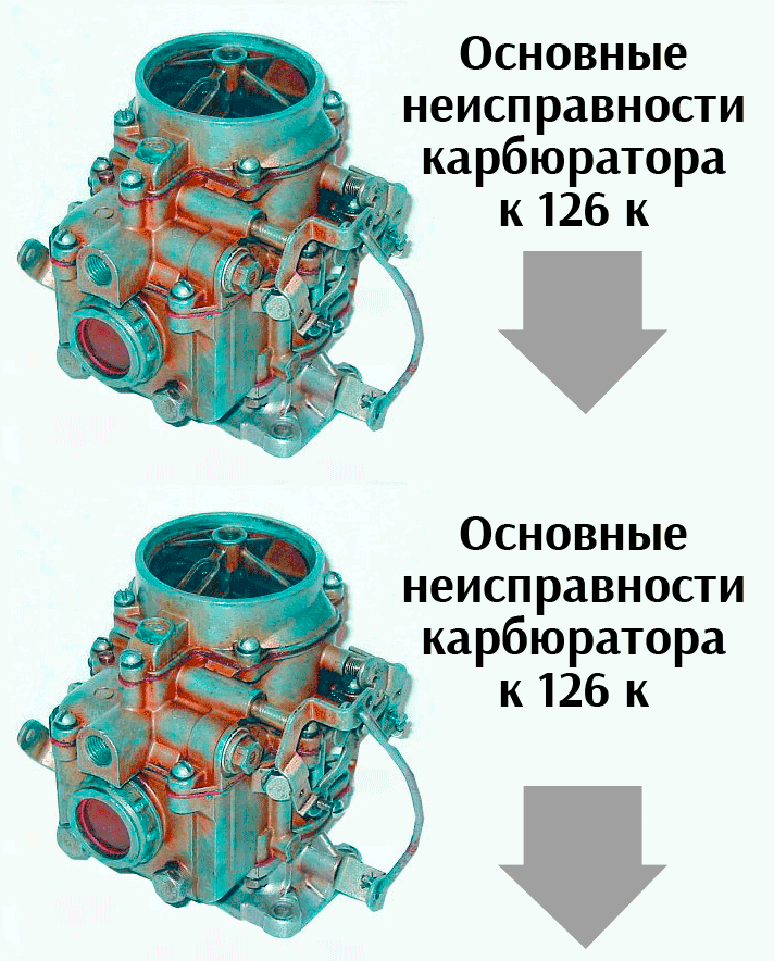
The main symptoms of the malfunction are listed below:
- The engine does not start, fuel overflow occurs due to the high level of the float chamber (the level is not adjusted).
- The motor does not start the first time, it wipes and stalls. The K 126 carburetor has a filter, which is clogged, the quality of the mixture is not acceptable and is not regulated.
- A lean mixture or a low level of gasoline in the float chamber are the reasons for skips, failures during the operation of the engine cylinders.
- Floating rpm and dips at idle speed let you know about a clogged XX jet, or a lean mixture.
- A decrease in power during loading indicates a clogged lean-burn jet.
- Increased fuel consumption is usually caused by improper adjustment of the powertrain fuel delivery unit load limit.
Of course, it is impossible to speak with confidence about the malfunction of the k126g carburetor installed on the UAZ, the device of which fails with the given signs. It is important to tune and check the engine, the entire fuel line, the ignition system is being refined by hand. Prevention, checking the condition and adjusting the carburetor and k126g units on the UAZ will never be an unnecessary procedure.
Before adjusting the needle with your own hands, you need to check the tightness of the connections and the connection of all underwater hoses. The required fuel level in the float chamber is set at the expense of the float level. A car standing on a flat surface warms up to operating temperature, after which it is muffled and the level is checked, it should be from 17.5 to 21 mm.
The applicability of tuning and setting up cold start units occurs without an extra tool, it is enough to connect the levers of the damper, drive with the correct sequence. The check is carried out by pulling the choke knob out of the passenger compartment to the maximum level, if in this case the air damper completely covers the chamber, and in the weakened position it opens, then the k126n system is working properly. The K 126 K carburetor requires setting the idle speed according to the diagram.
At the operating temperature of the engine, it is necessary to adjust the number of revolutions at idle, which should be 500 per minute, deviations upward are allowed during operation in the winter period.
Adjustment of the carburetor to 126 and idling parameters is performed as follows:
- The adjusting screw for the quality of the mixture setting is screwed in until it stops, and then it is unscrewed by 2.5 turns;
- The engine warms up to operating temperature, the speed is regulated by the opening angle of the throttle valve;
- The adjustment results are checked by abruptly pressing the gas pedal, the engine should not stall, there is a smooth drop in speed.
| Video (click to play). |
Adjustment is not particularly difficult and does not require the cost of tools and special tools. It is for this reason that the automobile plant produces K126gm carburetor cars, which are used under difficult conditions, remote from the services of a car service. Compliance with the frequency of maintenance will make it possible to operate the car for a long time without critical breakdowns.

