In detail: do-it-yourself repair of a carburetor to 126 gu from a real master for the site my.housecope.com.
You will familiarize yourself with the device of the K126 carburetor, learn how to adjust it, find information on the principle of operation of the carburetor.
The times of the k126 carburetor began in the 1960s. K126 carburetors were installed on domestic cars and light trucks. The k126 carburetor is still used in the vastness of the former Soviet Union and can still be easily purchased at auto parts stores.
The carburetor K 126 has many modifications, below I will give the information that I managed to find:
They differ in tops, parts, soles, diffusers, calibrations, etc.
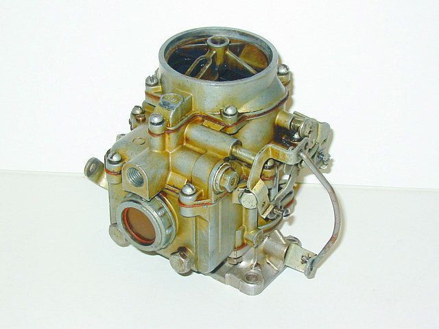
Consider the device of the carburetor k126. The k126n carburetor has a similar structure. The K-126 carburetor is an emulsion, two-chamber, with a falling flow, with sequential opening of the throttle valves and a balanced float chamber.
The carburetor has two mixing chambers: primary and secondary. The primary chamber operates in all engine modes. The secondary chamber comes into operation under heavy load (after about 2/3 of the throttle stroke of the primary chamber).
To ensure uninterrupted operation of the engine in all modes, the carburetor has the following metering devices: a primary chamber cold run system, a secondary chamber transition system, main metering systems of the primary and secondary chambers, an economizer system, a cold engine start system and an accelerator pump system. All elements of dosing systems are located in the body of the float chamber, its cover and the body of the mixing chambers. The body and cover of the float chamber are cast from zinc alloy TsAM-4-1. The mixing chamber body is cast from AL-9 aluminum alloy. Sealing cardboard gaskets are installed between the body of the float chamber, its cover and the body of the mixing chambers.
Video (click to play).
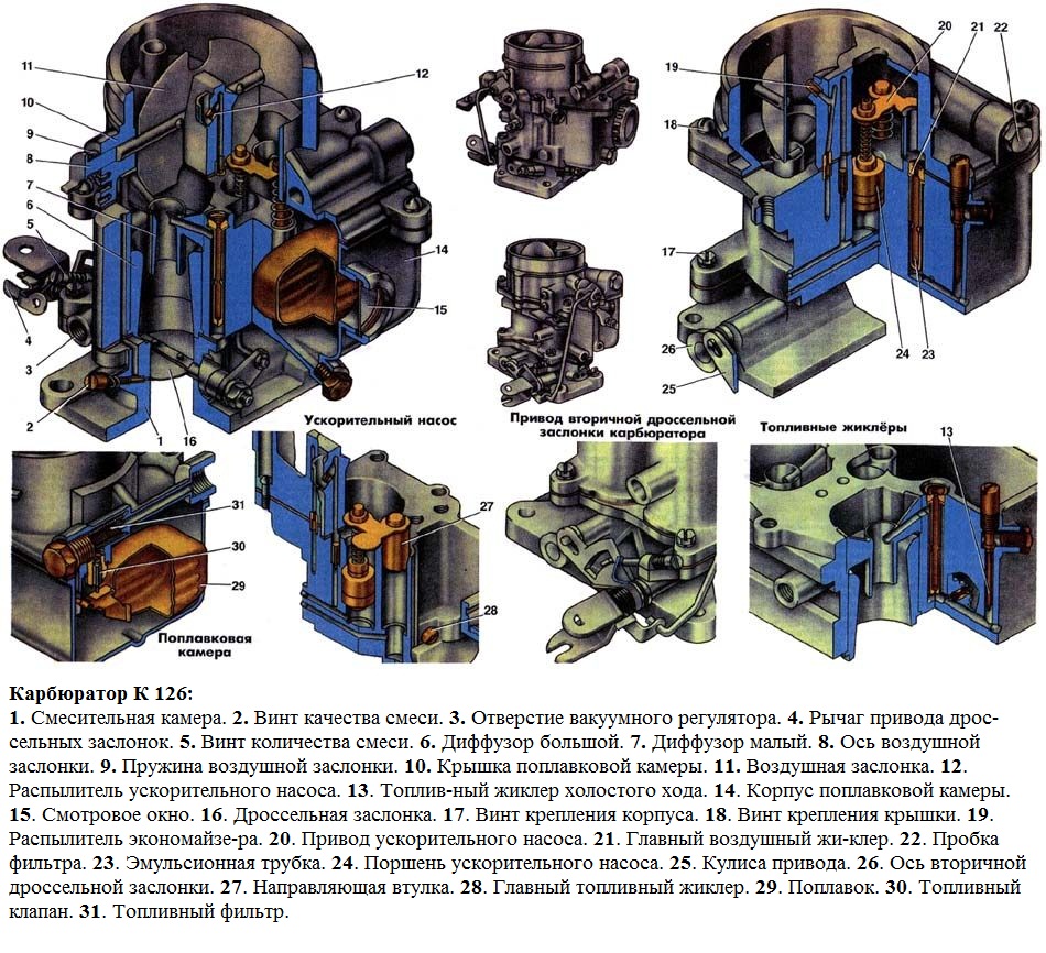
Carburetor device K-126
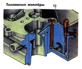
The body of the float chamber contains: two large 6 and two small diffusers 7, two main fuel jets 28, two air brake jets 21 of the main metering systems, two emulsion tubes 23 located in the wells, a fuel 13 and air jets of the idle system, an economizer and a guide sleeve 27, an accelerator pump 24 with delivery and non-return valves.
The nozzles of the main metering systems are led out into the small diffusers of the primary and secondary chambers. The diffusers are pressed into the body of the float chamber. In the body of the float chamber there is a window 15 for monitoring the fuel level and the operation of the float mechanism.
All channels of the jets are fitted with plugs to provide access to them without disassembling the carburetor. The idle fuel jet can be turned out from the outside, for which its housing is brought out through the cover up to the outside.
In the cover of the float chamber there is an air damper 11 with a semiautomatic drive. The air damper drive is connected to the primary chamber throttle valve axis by a system of levers and rods, which, when starting a cold engine, open the throttle valve to the angle necessary to maintain the starting engine speed. The secondary throttle valve is then tightly closed.
This system consists of an air damper drive lever, which acts with one arm on the choke axle lever, and with the other, through the rod to the idle lever, which, turning, presses the primary chamber damper and opens it.
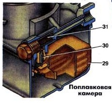
A float mechanism is mounted in the carburetor cover, which consists of a float suspended on an axle and a fuel supply valve 30. The carburetor float is made of 0.2 mm brass sheet. The fuel supply valve is collapsible; it consists of a body and a shut-off needle. Valve seat diameter 2.2 mm. The cone of the needle has a special sealing washer made of a fluoride rubber compound.
The fuel entering the float chamber passes through the 31 mesh filter.
In the housing of the mixing chambers there are two throttle valves 16 of the primary chamber and the secondary chamber, an adjusting screw 2 of the idling system, a toxicity screw, channels of the idle system, which serve to ensure the coordinated operation of the idle system and the main dosing system of the primary chamber, opening 3 of the vacuum supply to a vacuum ignition timing regulator; and a secondary chamber transition system.
The main carburetor systems operate on the principle of pneumatic (air) fuel braking. The economizer system works without braking like a simple carburetor. The idle, booster pump and cold start systems are available only in the primary chamber of the carburetor. The economizer system has a separate spray nozzle 19, which is led out into the air branch pipe of the secondary chamber. The secondary chamber is equipped with an idle transition system.
The idling system of the carburetor consists of a fuel jet 13, an air jet and two holes in the primary mixing chamber (upper and lower). The lower hole is equipped with a screw 2 for adjusting the composition of the combustible mixture. The idle fuel jet is located below the fuel level and is included after the primary chamber main jet.
Fuel jets of the carburetor k126
The fuel is emulsified with an air jet. The required performance of the system is achieved by the idle fuel jet, the air brake jet, and the size and location of the vias in the primary mixing chamber.
The main metering system of each chamber consists of large and small diffusers, emulsified tubes, main fuel jets and main air jets. The main air jet 21 controls the flow of air into the emulsion tube 23 located in the emulsion well. The emulsion tube has special holes designed to obtain the required performance characteristics of the system.
The idle system and the main metering system of the primary chamber provide the required fuel consumption at all main engine operating modes.
The economizer system consists of a guide sleeve 27, a valve 23 and an atomizer 19. The economizer system is put into operation at 5-7 until the throttle valve of the secondary chamber is fully open.
It should be noted that, in addition to the economizer system, the main metering systems of both chambers operate at full load and very little fuel continues to flow through the idle system.
The accelerating pump system consists of a piston 24, a drive mechanism 20 for the inlet and discharge (outlet) valves, and a spray nozzle 12, which is brought out into the air nozzle of the primary chamber. The system is driven from the primary chamber throttle axis and works when the vehicle is accelerating.
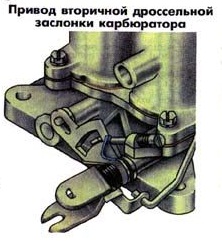
On the axis of the throttle valve of the primary chamber, the drive lever 4 is rigidly fixed. The link of the link 25 is also rigidly fixed on the axis. The link is freely installed on the axis of the damper 16 and has two grooves. In the first of them, the leash moves, and in the second, the pin with the roller of the lever 26 of the drive shaft 8 of the secondary damper fixed on it.
Second chamber throttle actuator k126
The flaps are held in the closed position by springs attached to the primary chamber axis and the secondary chamber axis.The rocker 25 also constantly tends to close the shutter of the secondary chamber, since it is acted upon by a return spring attached to the axis of the primary chamber.
When the lever 4 drives the axis of the primary chamber, the leash of the lever of the primary chamber first moves freely in the groove of the link 25 (thus only the damper of the primary chamber is opened), and after about 2/3 of its travel, the leash begins to rotate it. The rocker 25 of the secondary flap drive opens the secondary throttle valve. When the gas is released, the springs return the entire lever system to its original position.
Carburetors K-126 are very simple in design, moderately reliable and require minimal maintenance if used correctly. Most malfunctions occur either after unskilled intervention in the adjustment or in the case of clogging of the metering elements with solid particles. Among the types of maintenance, the most common are flushing, adjusting the fuel level in the float chamber, checking the operation of the accelerator pump, adjusting the starting system and the idle system.
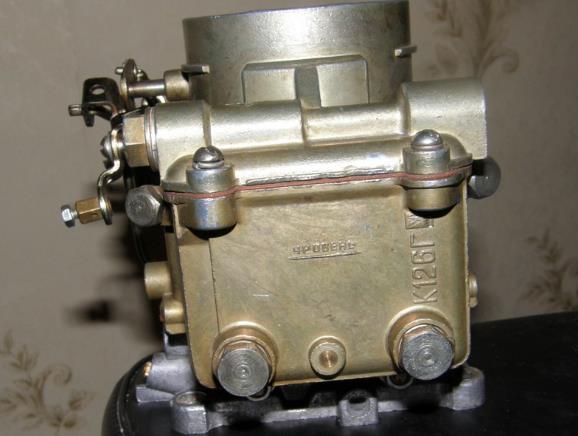
Consider adjusting the carburetor to 126 using the example of K 126GU.
K126 fuel level adjustment
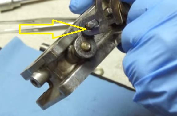
Check the fuel level with the engine off of a vehicle installed on a horizontal platform. When pumping fuel using a manual pump drive, the fuel level in the carburetor float chamber should be within the range marked by marks (tides) "a" on the walls of the inspection window. If the level deviates from the specified limits, make adjustments by removing the cover of the float chamber. Adjust the level by bending the tongue 3 (see fig.). At the same time bending the stopper 2, set the needle stroke 5 of the fuel supply valve to 1.2 - 1.5 mm. After adjusting, check the fuel level again and, if necessary, make the adjustment again. Considering that during operation, due to wear of the float mechanism, the fuel level gradually rises, set it when adjusting to the lower limit. In this case, the fuel level will be within acceptable limits for a longer time.
Note. When adjusting the fuel level in the carburetor float chamber, do not bend the float tab by pressing on the float, but bend it with a screwdriver or pliers.
Adjustment of the minimum idle speed is carried out in the following sequence:
- we warm up the engine to operating temperature;
- turn screw 15 all the way, but not tight, and then unscrew it 1.5 turns;
- start up the engine and with the stop screw 43 of the throttle valve set a stable crankshaft rotation speed of 550 - 650 rpm;
Checking the adjustment results is carried out by abruptly pressing the gas pedal, the engine should not stall, there is a smooth drop in revolutions
The screw 15 of the toxicity limiter adjusts the limit value of carbon monoxide (if equipped with a gas analyzer).
It is possible to adjust the idling system of the carburetor k126 without a gas analyzer.
This is how this procedure is described in the book by N.N. Tikhomirov. "Carburetors K-126, K-135":
In the absence of a gas analyzer, almost the same control accuracy can be achieved using only a tachometer or even by ear. To do this, on a warm engine and with the unchanged position of the "quantity" screw, find, as described above, such a position of the "quality" screws, which ensures the maximum engine speed. Now use the "quantity" screw to set the speed to about 650 rpm "1. Check with the "quality" screws whether this frequency is the maximum for the new position of the "quantity" screw.If not, repeat the whole cycle again to achieve the required ratio: the quality of the mixture ensures the maximum possible speed, and the number of revolutions is about 650 min. ”1. Remember that the "quality" screws must be rotated synchronously.
After that, without touching the “quantity” screw, tighten the “quality” screws so much that the rotational speed decreases by 50 minutes ”1, i.e. to the regulated value. In most cases, this adjustment meets all the requirements of GOST. Adjustment in this way is convenient in that it does not require special equipment, and can be carried out every time the need arises, including for diagnosing the current state of the power supply system.
In case of inconsistency of CO and CH emissions with the GOST standards at an increased speed of rotation (Nпов ", = 2000 * 100 min" ’), the impact on the main adjusting screws will no longer help. It is necessary to check if the air jets of the main metering system are dirty, if the main fuel jets are enlarged or if the level of fuel in the float chamber is too high.
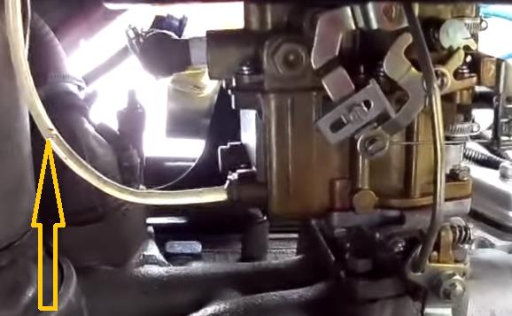
The K 126 carburetor, like all other carburetors, has its weak points. A very weak point in the carburetor k126 is the attachment of the lower part of the carburetor to the middle one, in this place the fasteners are over time exposed to heat from the engine side and in these places, with a strong constriction of the carburetor fastening, and at an increased operating temperature of the engine, the fastenings of the carburetor halves were deformed, as as a consequence, a gap appears between the lower middle part of the k126 carburetor, the transition channels of the idle system begin to suck in air and it becomes almost impossible to adjust the idle speed, this applies to almost all carburetors of the k 126 family.
Checking the plane of the carburetor flange
You can check the flange plane using a straight ruler, as shown in the figure (Solex carburetor is shown, the principle is the same). To eliminate this problem it is necessary to disassemble the carburetor completely, remove the large diffusers from the middle part, and grind both halves, replace the intermediate spacers with new ones and assemble the carburetor. After the engine has warmed up to operating temperature, adjust the idle speed and mixture quality.
A feature of the K-126 carburetors is that the adjustment is not particularly difficult and does not require the cost of tools and special tools. It is for this reason that the production of carburetor k126gm cars continues, which are used under difficult conditions, far from the services of a car service. Compliance with the frequency of maintenance will make it possible to operate the car for a long time without critical breakdowns.
Video about the device and repair of the carburetor k126.
It would seem that the era of carburetor cars has passed a long time ago, but no, these cars still roam on our roads today and at the same time "feel" quite confidently. One of these machines is the UAZ-452, better known by the nicknames "Loaf", "Baton", "Tablet".
"Loaves" from the first day of their production were equipped with carburetors of the K-126, K-129 type and their modifications. This continued until 1985, when the car was completely modernized. Along with the new, more powerful engines, the K-131 and K-151 carburetors, as well as their numerous improved versions, began to be installed on the UAZ-452.
But the simplest, most reliable and maintainable of them turned out to be the K-126 carburetor, which, among other things, was the most economical. If the engine with K-131 and K-151 consumed on average 15-17 liters of gasoline per hundred kilometers, then the K-126 made it possible to save 3-4 liters. All the latest models of UAZ-452 carburetors are interchangeable, except that the K-126 requires an additional gasket between its "fifth" and the intake pipe.
The K-126 line is a generation of carburetors produced by the Lenkars plant (Leningrad), which later became the famous Pekar.The first models of two-chamber K-126 were manufactured in 1964 for the new ZMZ-53 engine, which replaced the obsolete GAZ-51.
The carburetor consists of three main elements:
throttle assembly (mixing chamber bodies);
float chamber;
cover.
K-126G has two chambers for mixing fuel with air. The first one works in all modes, and the second one only at high loads, when the first throttle opens more than 2/3 of the stroke.
An air damper with a drive mechanism and a float mechanism are installed in the cover of the device. The float chamber contains diffusers, fuel and air jets, an accelerator pump, and emulsion tubes. The throttle assembly contains dampers (one in each chamber) and adjusting screws. In addition, there is a transition hole for the idle system, as well as channels for air and fuel.
accelerator pump (piston, inlet and outlet valves, drive mechanism).
Accelerator pump.
Main air jet of the secondary chamber.
Small diffuser of the secondary chamber.
Balancing channel.
Economizer sprayer.
Air damper.
Accelerator pump sprayer.
Discharge (outlet) valve.
Air damper rocker mechanism.
Idle air jet.
Small diffuser of the primary chamber.
Main air jet of the primary chamber.
Fuel valve.
Fuel filter.
Float.
Observation window.
Drain plug.
The main fuel jet of the primary chamber.
Primary chamber emulsion tube.
Throttle valve drive lever.
Primary chamber throttle valve.
Idling via.
Mix quality adjustment screw.
Idling fuel jet.
Secondary chamber throttle.
Large diffuser.
Secondary chamber emulsion tube.
The main fuel jet of the secondary chamber.
Non-return (inlet) valve.
Like any other mechanical device, the carburetor cannot run smoothly all the time. The reasons for this may be:
clogging of jets and channels;
wear of gaskets or seals;
violation of the regulation of systems and mechanisms.
Symptoms that the carburetor is in emergency mode include:
unstable idle (floating speed);
impossibility of starting or complicated starting of the power unit;
decrease in motor power;
jerks when starting from a standstill, as well as dips during acceleration;
increased fuel consumption;
detonation.
Naturally, these signs may indicate other problems in the fuel system or ignition system, but flushing, cleaning and adjusting the carburetor will not harm it in any way.
Use the table to determine a possible carburetor malfunction.
Maintenance of the device is reduced to cleaning and adjusting it. As for the frequency of such work, it should be carried out at least once a year, as well as when signs of a device malfunction are detected.
Carburetor cleaning involves the following activities:
external cleaning from dirt, dust, oil deposits of the throttle assembly, the body of the float chamber and the cover;
flushing and purging of nozzles, spray nozzle, fuel filter, emulsion tubes, holes and channels of the device;
cleaning the air and throttle valves.
Carburetor adjustment involves setting:
fuel level in the float chamber;
cold start systems;
idle system.
For complete maintenance, it is recommended to remove the carburetor from the engine and disassemble.
set of wrenches;
Screwdriver Set;
clean dry cloth.
Remove the air filter from the carburetor. Depending on the modification of the engine and the car itself, it can have a different design and different mounts. It is usually secured with a rubber hose and clamp.
In order to disassemble the device, it is necessary to disconnect the cover from the body of the float chamber, and then the body of the mixing chambers.
Unpin the upper end of the economizer drive rod. Disconnect the traction.
Use a screwdriver to unscrew 7 screws that secure the cover to the body of the float chamber.
Do not put the cover float down: the float mechanism will not adjust.
The carburetor throttle assembly is disconnected from the body of the float chamber by unscrewing 4 screws (caps are at the bottom).