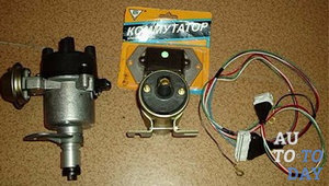
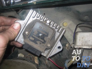
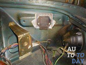
In detail: do-it-yourself gas switch repair from a real master for the site my.housecope.com.
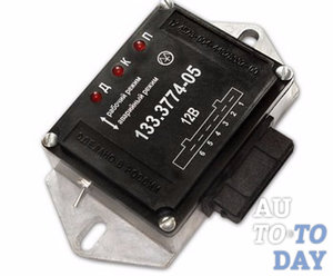
Currently, the widespread model of the GAZ-2705 GAZelle car is equipped with a contactless battery ignition system with an electronic switch 13.3734-01.
The schematic diagram of the electronic switch 13.3734-01 is shown in the figure. The switch elements are located on a printed circuit board, which is mounted inside a metal case, which is a cooling radiator for the output transistor VT2.
The elements of the switch circuit operate in a severe thermal regime under conditions of voltage and current fluctuations in the vehicle's on-board network.
Usually, switch malfunctions are associated with the failure of either the terminal transistor VT2 or the input diode VD2, which is easy to determine using an ohmmeter. For a more detailed check of the input circuits of the switch, it is necessary to apply voltage + (12… 13) V to the “+” contact from a stabilized power supply. A sinusoidal signal with an amplitude of 12 V and a frequency of 40 ... 80 Hz is supplied to the contact "D" from the generator of standard signals.
Rice. 2 Schematic diagram of an electronic switch
The oscilloscope controls the signal flow at the following points: the cathode of the diode VD3, the collector of the transistor VT1 and the pin. 14 microcircuits DA1. When repairing an electronic switch, in which the output transistor is broken, along with its replacement, it is advisable to replace the insulating mica gasket under its case measuring 18 x 23 mm and 0.21 mm thick with a gasket 0.1 mm thick. This will not affect the reliability of the switch, but will improve the process of heat removal from the output transistor.
| Video (click to play). |
To replace the VT2 transistor, you can use semiconductor devices KT898A, KT8109A, KT8117A, which are similar in parameters, and are specially designed to work in automotive ignition systems.
- Alexey / 09/14/2018 - 14:28
Bitter to read! Guys, did they teach you Russian? Where is this taught? At first glance, you have a grade 1 education and a corridor! Shame and disgrace! You need to know your native language not only spoken, but also written! Learn before it's too late! - Ed / 07/25/2017 - 07:20
should be from the VT1 collector goes to the R7 C4 connection and to the 5th pin of the microcircuit, R7 the upper end to the right R8 pin. - zhorik / 12/14/2015 - 10:19
Why does the UAZ hunter car stall after heating on the move like there is no current, the starter turns great, but does not start after a day or a couple of hours - nnn / 08/23/2015 - 11:27
commutator on the diagram 131 and not 13 3734 - Anatoly / 04/07/2014 - 07:33
Ana, how often does the k1055HP1 chip fly out? —– Well, it's hard to predict .. It mainly depends on the quality of workmanship. and If you do not violate the mode of the microcircuit, But the electronics has its own duty cycle. as well as the pac bulb. Anatoly. - Pavel / 05/20/2013 - 13:16
why is the ignition coil warming up even though everything has changed: coil switch - Anatoly / 02/14/2013 - 18:35
Kind time of day, everyone. I have a question of this order, but has anyone tried to connect instead of the sensor to the switch input 13.3774-01, the native contacts of the distributor? —So the camutator will not work for a long time .. will sigh. this time and the second zboy ignition. will trait. tested on Zhiguli. - Olezha / 02/14/2013 - 18:24
why are the "runners" burning in the contactless system. Coil B-116, tr. 131 3734. — Look at the tramler cover, it may be the fault of the crack. - Anatolij / 02/14/2013 - 06:46
dear! maybe YOU can tell me WHERE to find such "lectures" on a slightly different switch 12.3774 (analogue 3660.3737, 13.3734). nowhere can I find any schemes or comments. I will be extremely grateful (Well, vaabsche then, in principle, the differences between them do not have one principle in their work.The camutator is an electronic key. The difference between them is the wiring of the connector of the camutator itself .. The effective outputs are power + and - output to the coil of the ignition coil and (D) the dacha who goes to the tramler, there are summer cottages called (hall) they need power + also - and the third conclusion is (D) which goes to the kamutator, this is the control of the kamutator, On the size of the tramler itself, there are three outputs, which in the middle eats the exit (D), that is, the dachik. - Anatoly / 02/14/2013 - 05:43
I was surprised by R7 Why is he. (This is just a typo or error. T1 is just a key and R7 is not needed there. - Anatoly / 02/14/2013 - 05:28
but which one is better to replace the KT 837 x transistor? (Look at the manual. Pay attention to the current and voltage, they must be high-voltage. The lower the voltage, the less chances for the transistor to survive. The reference data can be found in the internet. - Anatoly / 02/14/2013 - 05:11
Thank you all. And there is electrolyte or not near R7. Who knows. (Steam it yourself, there will be a positive or negative result, also a result. And finally, saber a simple stent without a tramler. (Kamutator and babin). that is, on the Masu). Well, in the past, you will understand my log— —– = - = - Anatolij. - Anatoly / 02/14/2013 - 05:09
Thank you all. And there is electrolyte or not near R7. Who knows. (Steam it yourself, there will be a positive or negative result, also a result. And finally, saber a simple stent without a tramler. (Kamutator and babin). that is, on the Masu). Well, in the past, you will understand my log— —– = - = - Anatolij. - Vasily / 11/18/2012 - 08:27
why are the "runners" burning in the contactless system. Coil B-116, tr. 131 3734. - Pramjeet / 03/23/2012 - 04:34
I'm not wrohty to be in the same forum. ROTFL - Vladimir / 03/22/2012 - 17:09
Kind time of day, everyone. I have a question of this order, but has anyone tried to connect, instead of a sensor, to the switch input 13.3774-01, the distributor's own contacts? - hiio / 26.02.2012 - 20:28
ATTENTION ALL. SEVERE ERRORS FOUND IN THE DIAGRAM OF THE SWITCH 13.3734-01 IN THE PICTURE WHAT SHOULD BE CHANGED TO MAKE THE SCHEME IN ACCORDANCE WITH THE FACTORY ASSEMBLY: 1) UPPER END OF RESISTOR R7 AND UPPER END OF C5 CAPACITOR SHOULD BE CONNECTED TO THE 3RD FEET OF THE MICRO. 2) REAL NOMINALS OF C7 AND C8 CAPACITORS - PER 2.2 MKF. (THE PICTURE SHOWS THE VALUE OF THEIR NOMINAL IN 22MKF.) ALL SUCCESS. - Alexander / 23.01.2012 - 19:02
There is a DIODE! - Kinap / 08/19/2011 - 05:20
Ana, how often does the k1055HP1 chip fly out? - Kinap / 08/19/2011 - 05:17
And how often does the k1055xp1 chip fly out?
12Forward
You can leave your comment, opinion or question on the above material:
If with some malfunctions on the car you can somehow get to the repair point, then with a faulty switch, the engine will not start at all. Some drivers often carry a spare switch with them. In this article, we will consider the principle of operation, some malfunctions of the automotive switch and how to repair it.
- Often the switch breaks down due to water ingress into it. As a result, the kr1055hp4 microcircuit (analogue of L497B) fails,
- Due to overvoltage or from time to time, the output transistor of the type KT8231A1, KT8225A, KT8232A1, KTD8252A, KTD8264A, KTD8267, KT898A, KT8127A1 (analogue of BU941ZP) often fails.
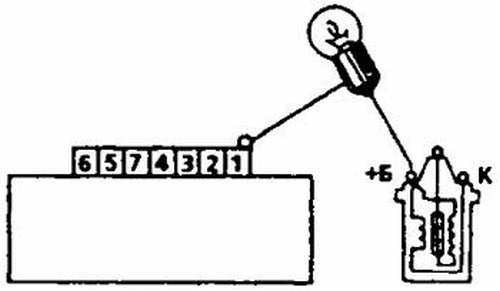
To test the switch, we assemble such a simple stand as in the figure below. We connect a 12 V light bulb instead of a coil.
When we turn the axle of the distributor with the DH (hall sensor), the light comes on. When we do not turn and the light does not light up.
The Hall sensor is a magnetoelectric device that got its name from the surname of the physicist Hall, who discovered the principle on the basis of which this sensor was later created. Simply put, it is a magnetic field sensor. There are two types of Hall sensors: analog and digital.
Analog Hall sensors - convert the field induction into voltage, the value shown by the sensor depends on the polarity of the field and its strength. But again, you need to consider the distance at which the sensor is installed.
Digital sensors detect the presence or absence of a field. That is, if the induction reaches a certain threshold - the sensor gives out the presence of the field in the form of a certain logical unit, if the threshold is not reached - the sensor gives out a logical zero. That is, with a weak induction and, accordingly, the sensitivity of the sensor, the presence of a field may not be detected. The disadvantage of such a sensor is the presence of a dead zone between the thresholds.
Digital Hall sensors are also divided into: bipolar and unipolar.
Unipolar - they work in the presence of a field of a certain polarity and turn off when the field induction decreases.
Bipolar - they react to a change in the polarity of the field, that is, one polarity turns on the sensor, the other turns it off.
- Measure the voltage at the sensor output. It must be more than 0.4 V.
- Check for a spark when the ignition is turned on. To do this, you need to close the 1 and 2 output of the switch with a wire.
- Replace with a known good one.
Some switches have a different "logic" output. Some, for example 131.3734-01 - have a logical "1", while others have a "0". Who has "1" by default (this is when the device shows 12 volts or close to them by default between the contacts "+" and "short circuit") actually run the risk of burning the coil at the moment when the ignition is turned on and the engine does not work, creating a one-sided potential inside the coil and without discharging it, thereby you can feel the rapid heating of the coil with your hand. The created potential begins to discharge only when the engine is running. The advantage of such switches is that you can use conventional (native) coils for contact ignition practically without disturbing the old coil connection circuit. The switch in this case is inserted into the wire break from which went from the breaker contact to the coil. The Trambler is simply replaced and a switch is added.
In the switch, for example BSZ 131.3734, the default logic "0" is observed. If with the coil of the switch kit 131 3734 you put it with logic "1" by default, then the coil will be terribly hot. Or, on the contrary, on the coil intended for a switch with logic "1", put switch 131 3734 - logic "0", then either there will be no spark, or it will be very weak, or you can even damage the switch.
This mode of operation is not rational for either the front wiper or the rear. The latter in this case often runs "dry", since fewer rain drops fall on the rear window (although this is compensated by a large amount of dirt). However, batch wipers have been known for quite some time. Therefore, the proposed system is of certain interest for all vehicles, given its low cost. More details ...
In amateur radio circuits, there is a need for frequency-voltage conversion, for example, to measure the frequency with a voltmeter (multimeter), a sensor that responds to frequency changes, etc.
On a rainy day, I climbed under the hood, check everything, and after closing it did not start. Diagnostics led to switch 131.3734-11, which I had fashionable and with a multi-spark start.
The installation of the old Soviet switch 1302.3734 made it possible to reveal what was the matter, after which the Soviet hero also died, since the additional resistor was short-circuited and I completely forgot to return everything as it should 🙁 And the coil is all over the place, this is a tank B-116.
And the matter was in the high-voltage output of the coil, which, from the degradation of the rubber-insulator, began to be stitched onto the terminals of its own power supply (into the low-voltage part). Apparently, the switch died from such high-voltage overloads at the output.
I put a new insulator on the high-voltage terminal of the coil, securely and overlapping it with Safeline electrical tape (Yes, it matters. Whoever used it will understand). I realized such a thing that the central outlet of the coil is a rather dangerous enemy and the most responsible place.
So far I have installed a standard "Volgovskiy" switch 131.xxx in an aluminum case.
The deceased 131.3734-11 still diagnose ... a strange death. It is made soundly, the board is filled with something like liquid rubber, all contacts are soldered neatly and properly, with insulating gaskets. It would be necessary to find out what exactly should be protected from explosive breakdowns. Bidirectional protective diodes today are not difficult to buy and make an unbreakable switch.
- How to check the switch with your own hands?
- 1. Symptoms of Switch Malfunction
- 2. Algorithm of actions for checking the switch
- 3. Materials for checking the switch
Switch problems are one of the most common causes of powertrain operational failures. (of course, provided that everything is in order with the fuel system). Most often, switch malfunctions are manifested in the form of a drop in acceleration dynamics, failure to start the motor, "failures" during sharp acceleration, as well as "triplet" of the engine. An experienced driver will immediately notice that something was wrong, and to be convinced of his theory, it will be enough to carry out a simple diagnosis.
The most common cause of switch failure is "poor weight", which most often manifests itself after lengthy repair work or due to oxidation of the contacts. As a result, the device simply cannot send appropriate pulses to the ignition coil, and without them the engine will not start and the car will not start.
For example, to check the state of the proximity sensor, you need to measure the voltage at the output of the sensor - distributor. In good condition, turning the crankshaft with a key should cause a sharp change (often in the range from 0.2 - 0.4 V to 5 - 11 V). If this does not happen, the sensor most likely needs to be replaced. Diagnostics of the switch status also does not take much time, and most often it does not require any special equipment to complete it.
Many motorists prefer not to waste time troubleshooting, but to immediately replace the switch with a new node. In principle, there is logic in such a solution: Firstly, you do not have to waste time on checking, Secondlyby installing a new part, it will immediately become clear whether it is a problem or not. True, you do not need to worry about the time spent, because the switch diagnostics will not delay you for a long time.
There are two main ways to test a switch. The first one is a little simpler and requires a carrying lamp. The algorithm for carrying out the procedure in this case is as follows:
1. Disconnect the wire from the switch terminal from the ignition coil;
2. We connect the free tip of the wire to the test lamp, and the second terminal of the lamp to the terminal of the ignition coil;
3. Turn on the ignition and turn the engine crankshaft using the starter.
In this case, the sequence of performing the test steps is slightly different. To begin with, you should know the specific designations located on the device case. Often these designations are presented in the form of Latin letters (for example, B, C, T, K).
Secondly, you need to understand that when checking the device, you need to pay attention to the reliability of the connections, and there must be a good "minus" on the case itself. Quite often, after lengthy repair work or under the influence of oxidative processes, certain problems arise in the operation of the switch, due to "poor weight".
To check, the switch together with the ignition coil must be placed on one metal sheet, which acts as a "mass", and once again check the reliability of all connections, as well as the distance from the ignition coil (more precisely, the "outlet on it") to the metal sheet. The value of this distance should correspond to 15-25 mm.
At the next stage of diagnostics, you should alternately close and open the wire that should go to the switch contact. It is connected to a control 12-volt lamp, and according to general rules, the unit signal should not exceed 5 V.
However, if you apply these same 12 V for a short time, then you can check the switch in two directions at once: for its serviceability and for the quality of work in "extreme" conditions.
To check the operability of the internal switch, they perform all the same actions, only another contact is removed and substituted.
To test the switch, in both of the above cases, you will need a test lamp with a nominal voltage of 12 V and a standard set of keys with which you can verify the presence or absence of pulses (that is, the device itself is in good working order). The second diagnostic option provides for the presence of other elements: the most common button, a soldering iron and a metal sheet as a "mass".
However, if you do not want to waste time at all, then you just need to buy a new device to test the switch's health. If everything goes well after installation, then the problem really was in the old item.
Conference of the Skoda Car Lovers Club
2. Criteria for choosing a switch 131.3734. In 2000, in the magazine "Behind the wheel" number 3 was a review of switches for GAZ "Volzhskie arsonists", and the addition of "Volzhskie arsonists 2". I highly recommend reading these articles. Much of them is still relevant today. Based on this article and personal experience, I want to give some tips:
A. The switch is desirable in a massive aluminum case, if the case is plastic, then a massive radiator is required. Otherwise, overheating cannot be avoided.
B. Personally, I like the switches of the Stary Oskol plant, as well as the Energomash plant from Kaluga (don't count it as an advertisement). The latter is good in that it geometrically fits on the standard Felicia mounting studs.
V.The choice of a switch must be approached with all responsibility, there are a lot of fakes and hack products. Comments on the forum about the fact that the engine after replacing the switch does not work as it is, are most likely caused by a fake or not a high-quality product. For "Stary Oskol" everyone is not too lazy, pay attention to the marking, it is better to study the product on the manufacturer's website. Flimsy switches in plastic cases with tin bases should be avoided.
3. Some Filevody are interested in whether it is possible to put the switch 13.3734 instead of 131.3734. The answer is unequivocal - NO. This is impossible without rework.
4. About replacement of the ignition coil. The switch microcircuit itself optimizes the current through the output transistor and the primary winding of the ignition coil, regardless of the coil used. So any coil from high energy ignition systems can be used. Be it VAZ, GAZ, BOSH, dry, oil-filled. The main thing is that the resistance of the primary winding is about 0.5 ohms. Do not use coils from a contact (classical) system (resistance 3-5 ohms). Only the high-voltage wire may not come to the end. On Felicia, a more modern wire tip is used, like on injection VAZs.
5. Self-repair of the switch. For people who know how to hold a soldering iron in their hands and are familiar with the basics of electronics, it will not be difficult to make minor repairs to the switch. This is possible if it is collapsible. As a rule, a powerful output transistor fails. Open the switch and inspect the board. If the elements or the board itself are charred, then repair is hardly advisable. If everything is in order, then the transistor can be replaced. There are several domestic analogues of the BU931 transistor: KT890A, KT898A, KT8225A, KT8232A1. They can also serve well. But pay attention to the fact that the transistors are in the same package.
Last year, the magazine "Za Rulem" # 3 published an article from the Volga arsonists
So, yesterday 4 faulty switches 131.3734 fell into my hands - Kaluga, Starooskolsky, Ulyanovsk, etc. I do not know in what city and in what basement it was made.
After a detailed inspection, there was a desire to share my comments on the switches and the magazine article.
1. All switches have one drawback - it is advisable to perform the voltage divider R11 and R12 in the current feedback circuit with one trimming resistance of 560-680 Ohm. In this way, the switching current can be adjusted more precisely.
2. Regarding the Ulyanovsk commutator - the claims of the ZR magazine to the print resistance are clearly groundless. The conductor pattern allows the breaking current to be adjusted. And the divider in the feedback circuit is made with the same conductor. With a radiator, the matter is more complicated, but not hopeless. The fact is that the cooling area is quite sufficient, but the contact patch of the power transistor with this very radiator. let's say uneven. Those. the transistor is not in contact with the radiator with its entire plane. This is very bad. But you can put your hands to fix this design defect. Or lower the breaking current to prevent overheating of the transistor. But the printed circuit board of this switch is beyond praise. In a good way. It contains all the necessary markings, which greatly facilitates the repair. But the lid flush (it is also the radiator), if not one-time, then only two-time.
3.Stary Oskolsky. Although it may not be theirs. But very similar. It is not the output transistor that fails, but VT1. The fact is that there should be KT683. And there is KT315K. The same transistor is at the input. But all the same, it is better to use KT630B, which has the best parameters and endurance. By the way, this can be attributed to all switches, except for.
4. Kaluzhsky, who really became the leader of the switches that came to me. What is faulty in it, I have not yet figured out. I left it for last to savor. But, judging by the remark of ZR about the high switching current, then this current must be adjusted by feedback (R11 and R12).An oscilloscope is indispensable here.
5. And the last one. Words are not enough for criticism. But the trouble is that outwardly it is no different from Starooskolsky. Even the badge is worth it. It looks like the hulls are being stolen from the factory.
Now a few recommendations for repair. What do you need.
Power supply for 12V and 1A;
light bulb (possible from dimensions)
Well, of course, a soldering iron, screwdrivers, tweezers, etc.
We open it. 2 screws on the cover and 4 board. We examine carefully. Ishem traces of darkening. These are heating spots. If the “indicator” (-)))) resistance was very hot, it means that the power transistor (KT892) is faulty. We change. We fasten the board with one screw (for the radiator), and assemble the circuit - power and a light bulb instead of the ignition coil. We close the positive terminal of the switch and the sensor input and open it. The light should come on and, after a second or two, go out.
In Starooskolsky switches, the transistor VT1 usually burns out, because is not the one. This can be seen from the characteristic darkening of the transistor case and the absence of voltage at pin 3 of the microcircuit. In this case, the power transistor does not fail. KT315 is soldered and KT683 is soldered instead. Possible replacement - KT815, KT817. You can put KT630B. In principle, you can do without this transistor by soldering a resistance of 5-10 ohms with a power of 1 W instead. Checking is carried out in the same way as when replacing a power transistor.
Sent: Dmitry M., February 22, 2001 at 12:16:57
original is here
At present, the widespread model of the GAZ-2705 GAZelle car is equipped with a contactless battery ignition system with an electronic switch 13.3734-01.
The schematic diagram of the electronic switch 13.3734-01 is shown in the figure.
The elements of the switch circuit operate in a severe thermal regime under conditions of voltage and current fluctuations in the vehicle's on-board network.
Usually, switch malfunctions are associated with the failure of either the terminal transistor VT2 or the input diode VD2, which is easy to determine using an ohmmeter. For a more detailed check of the input circuits of the switch, it is necessary to apply voltage + (12.13) V to the "+" contact from a stabilized power supply. A sinusoidal signal with an amplitude of 12 V and a frequency of 40. 80 Hz is fed to the contact "D" from the generator of standard signals. The oscilloscope controls the signal flow at the following points: the cathode of the diode VD3, the collector of the transistor VT1 and the pin. 14 microcircuits DA1. When repairing an electronic switch, in which the output transistor is broken, along with its replacement, it is advisable to replace the insulating mica gasket under its case measuring 18 x 23 mm and 0.21 mm thick with a gasket 0.1 mm thick. This will not affect the reliability of the switch, but will improve the process of heat removal from the output transistor.
To replace the VT2 transistor, you can use semiconductor devices KT898A, KT8109A, KT8117A, which are similar in parameters, and are specially designed to work in automotive ignition systems.
No. 10 "Repair & Service" October 2001
A characteristic feature of the car can be considered its rapid obsolescence, but long life. The most modern car today, at least in two years, will be inferior to other, newer, with improved characteristics, cars. But even now on the roads there are cars of the last century. Therefore, it is not just interesting, but sometimes necessary, to know at least in general terms what such vehicles are, their structure, features, including such a thing as a simple ignition switch, which significantly changed the capabilities of the car.
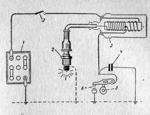
Even on the very first cars, battery ignition systems were used to ignite the combustible mixture, the functional diagram of which is shown in the figure
This figure makes it possible to understand that its work is based on the principle of self-induction.When the current flow circuit is broken in the winding of the bobbin 3, a high-voltage EMF is induced in the secondary, causing a spark on the contacts of the spark plug 2. The circuit break is caused by the opening of the contacts of the breaker 6.
Without touching on the merits or demerits, it should be noted that such a scheme worked on the car for a long time. And only the appearance of a new element base gave impetus to the further development of such a device, while retaining the original principle of its operation.
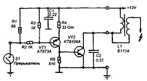
The simplest and most obvious option is to use transistor switches to control the currents flowing through the ignition coil. This is how the electronic voltage switch appeared. A diagram of such a simple device is shown below:
The switch does not affect the original electromagnetic induction principle. The role of electronic keys, which are used as transistors VT1 and VT2, is to reduce the load on the contacts of the breaker S1 and increase the current flowing through the coil winding L1. The consequence of this technical solution was:
- improving the reliability of the entire ignition system;
- ensuring the possibility of its operation at high engine speeds and at high travel speeds;
- increasing the compression ratio.
The above switch diagram is just one of the options for how an ignition device can be implemented. This is accomplished using:
- transistors;
- thyristors:
- hybrid elements;
- contactless sensors.
The transistor switch circuit is discussed above, the thyristor circuit uses energy storage in a capacitor, and not in the electromagnetic field of the ignition coil. During the operation of the thyristor system, when control signals are received, the circuit connects a charged capacitor to the windings of the coil, through which it is discharged, causing a spark to appear. Without touching on the advantages and disadvantages that this or that circuit possesses, suffice it to say that any such device provides a significant improvement in all parameters of the ignition system, and the switch eventually replaced the conventional battery ignition.
However, it is necessary to note one more stage in the development of the system, and the switch in particular. The use of electronic components and the introduction of a switch into the design of the car made it possible over time to abandon the contact voltage breaker and replace it with a contactless sensor. Such a system, in domestic cars, was first used in VAZ cars, in particular the VAZ 2108. A similar principle of operation, when the switch receives signals from a special unit, is implemented on the VAZ 2108 using a Hall sensor.
When considering options for what the switch device may be, one cannot ignore the development of the ignition system itself. The main principle that is implemented during its construction is to increase the reliability and efficiency of the entire system. This is achieved by using microprocessor systems using the readings of numerous sensors. To work with such systems, at least a two-channel switch is required, and recently a separate coil and a switch for each candle.
This approach - a two-channel switch (hereinafter multi-channel) allows you to provide:
- a more powerful spark;
- elimination of losses in the distributor;
- stable idle;
- improved starting at low temperatures;
- reduced fuel consumption.
It is worth noting that a two-channel switch allows you to get rid of the slider.
The introduction of an ignition switch into the design of a car, especially on domestic cars of the VAZ family, made it possible to increase their reliability. And although the VAZ 2108 was the first production car with an electronic ignition system, similar devices began to be installed on many other cars, primarily on the classics.However, the use of such a rather complex product led to the fact that it became possible to find the arising malfunction, as well as to check and repair the switch, for the most part only in the conditions of specialized centers.
External signs indicating that a malfunction has appeared may be:
- the engine does not start, there is no spark on the candles;
- the engine starts, but stalls after a few minutes;
- the motor is unstable, if the switch is replaced with a known good one, the defect is eliminated.
The easiest way to troubleshoot and test a switch, as noted, is to establish a known good switch. Due to the rather low quality of switches supplied to complete the VAZ family cars, including the VAZ 2108, drivers have to carry additional switches with them to replace the failed one. However, there is also an indirect assessment principle that allows you to check the performance of the product and identify its malfunction.
To do this, you can use the readings of a voltmeter in a combination of the device. It is necessary to turn on the ignition, while the arrow will settle in the middle of the scale, and after a while it will swing to the right (due to the disconnection of the coil power when the engine is not running). This behavior of the arrow indicates that there is no fault in the switch.
In the event that there is no voltmeter, a test lamp is required to check the ignition. One end of it is connected to ground, the other - to the output of the coil, connected to terminal 1 of the commutator. If you turn on the ignition, then with a working switch, after a while the lamp will become brighter.
However, in some cases, an ignition malfunction is not related to a switch failure. It is necessary to check the condition of the wires, first of all, the contact with ground and the condition of the connectors. It is also necessary to check the Hall sensor.
The appearance of a voltage switch in the design of a car, including the domestic VAZ 2108, was a natural result of the development of the ignition system. Its further improvement was the use of first two-channel and then multichannel switches to improve work efficiency.
- Like
- I do not like
Hello everyone! After replacing the cabin of the st.obr with a new one, the switch constantly burns out, I have already changed 5 pieces https://my.housecope.com/wp-content/uploads/ext/3317/forum/public/s. What to do?
how it burns out immediately when the ignition is turned on or after a minute or three hours, in more detail
Hello everyone! After replacing the cabin of the st.obr with a new one, the switch constantly burns out, I have already changed 5 pieces https://my.housecope.com/wp-content/uploads/ext/3317/forum/public/s. What to do?
Hello everyone! After replacing the cabin of the st.obr with a new one, the switch constantly burns out, I have already changed 5 pieces https://my.housecope.com/wp-content/uploads/ext/3317/forum/public/s. What to do?
Remove the distributor cover and bend the plate closer to the body. Not every coil will work with the switch, maybe you have changed something while the cabin was changed. Look in the books, there is somewhere about compatibility. Check the mass on the switch, without it it will not work either If this does not help then throw snot, I hope you will not get lost in 3 wires.
- Like
- I do not like
how it burns out immediately when the ignition is turned on or after a minute or three hours, in more detail
Check the weight on the cab and engine!
I checked the mass - I have cleaned everything
Yes, in the wiring, there is a jamb. Above, they advised you already, throw new wires (snot) on all the ignition, and throw off the regular ones. if the problem persists, then the jamb is in the distributor (plate) or coil or in the switch itself.
- Like
- I do not like
Vovan716, Take note of 134 message 3911 & st = 120 and check the voltage of the on-board network (for a switch, a voltage of more than 15 volts is detrimental, I suppose it's in the gene at some point there is a voltage surge of more than 15v in the car's network), sign
Yes, everything is fine with the gene 2 pieces set everything ok The voltage of the onboard network is normal.
Yes, everything is fine with the gene 2 pieces put everything ok https://my.housecope.com/wp-content/uploads/ext/3317/forum/public/s. The voltage of the on-board network is normal.
Did you change Babin by chance? Each switch has its own babin. Moreover, did you connect the additional resistance correctly?
Post has been edited by Pomor: 10 June 2009 - 20:21
- Like
- I do not like
Pomo
r, I changed the coil, but the switch felt 70-80 degrees https://my.housecope.com/wp-content/uploads/ext/3317/forum/public/s. Should he be so warm?
Look at the number on the old reel, and put the same one. And the add-on should warm up, but not to such an extent. It looks like it's all about the coil.
- Like
- I do not like
two pieces burned out, now I put 131.3734, the flight is normal, the coolest thing is that it does not understand https://my.housecope.com/wp-content/uploads/ext/3317/forum/public/s. , instead of rivets bolts (I wanted to erode from the transistor
gasket on advice MetalVoice)
+5
The same problem, the switch is enough for 1 day. Only I did not change the cab. An electrician I know said that the Hall sensor is being produced. Now I will change the distributor, coil and switch
| Video (click to play). |
Dear! Spit in your electrician's face! In the distributor on the 402 engine, NO. Hall sensor! There is a completely different system! Based on induction of EMF by a permanent magnet!
Post has been edited by Igor: 15 June 2009 - 18:15

