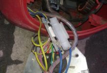
In detail: do-it-yourself switch repair from a real wizard for the site my.housecope.com.
Ignition systems for gasoline engines of domestic passenger cars VAZ-2108, VAZ-2109, ZAZ-1102 contain an electronic switch. It is designed to generate current pulses in the primary circuit of the ignition coil.
In electronic switches of domestic production (series 3620.3734; 36.3734; 78.3734), the functions of the output current switch are performed by a powerful transistor, and the functions of controlling the parameters of current pulses (normalizing the duty cycle of starting pulses, programmed regulation of the time of accumulation of energy in the ignition coil, limiting the current level in its primary winding and amplitudes of pulses of primary voltage) is performed by a low-current electronic circuit, more often in an integrated version.
The first domestic electronic switch with controlled parameters of ignition pulses (series 36.3734) was developed for the VAZ-2108 car. The switch used a K1401UD1 microcircuit, a powerful key transistor KT848A and other elements of domestic production.
The input information signal for the commutator is the signal from the Hall sensor located on the ignition distributor shaft. According to this signal, the switch receives information about the number of engine revolutions and the position of its crankshaft. The switch is designed to work with a serial ignition coil 27.3705.
The switch was a prototype for the development of subsequent series, which have several design and circuit design options. However, the combined integral-discrete assembly technology, which makes them maintainable, is still common to domestic switches.
| Video (click to play). |
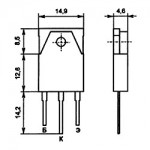
In modern domestic switches, specialized output key transistors of the types KT890A, KT898A1, BU931 (foreign) are used in several designs: TO-220, TO-3, without package. In some switches, for example 78.3734 (Fig. 4), a four-channel operational amplifier of the K1401UD2B type is used as a control microcircuit.
The switches also widely use the SGS-TOMSON L497B control microcircuit (domestic analogue Р1055ХП1). The block diagram and the recommended option for its inclusion are shown in Fig. 1, and the purpose of the conclusions is in table. one.
Before you start troubleshooting and repairing the electronic switch, you should:
• check the integrity of the car wiring, the reliability of the contact connections of the ignition system, the serviceability of the elements of the ignition system (plugs, ignition coil, Hall sensor, high voltage wires);
• check the serviceability of the car generator, as well as its integral voltage regulator;
• check the supply of voltage from the on-board network (with the ignition switch turned on) to the contact "P" of the Hall sensor connector.
The signs by which malfunctions of electronic switches are manifested, the most probable causes of these malfunctions and ways to eliminate them are summarized in Table. 2.
The basic electrical circuits of the ignition switches are shown in Fig. 2 (switch 3620.3734 - I), Fig. 3 (switch 3620.3734 - II) and Fig. 4 (switch 78.3734).
In conclusion, the following should be noted:
1. A close analogue of the foreign transistor BU931 (see diagrams in Fig. 2 and 3) is the domestic KT898A1. These transistors have a wide range of parameters, which leads to the need to select the ratings of radioelements in its base and emitter circuits, for each transistor separately.
2. Resistors R7 (see fig. 2) and R6 (see fig.3) serve to set the required current value through the powerful key transistors of the described switches.
An increase in the value of the resistors leads to a decrease in the current and vice versa.
Thus, by changing the values of these resistors, you can select the optimal current and thermal modes of operation of the output key transistors.
3. When replacing a powerful key transistor, you should pay attention to the quality of attachment of the transistor to the heat sink (case) of the switch. Also check for the presence of heat-conducting paste between the transistor and the radiator (switch case).
4. An analogue of the foreign zener diode 1N3029 (see Fig. 3) is the domestic KS524.
5. An analogue of the foreign microcircuit L497B (see Fig. 1, 2, 3) is the domestic KR1055HP1.
6. After replacing faulty radio elements in the switch, each new element on the board and the place of its soldering should be covered with nitro varnish. When assembling the switch case, coat the cover around the perimeter of the seal with a waterproof sealant (for example, "Hermesil").
Internet switch
In the topic touched upon: "How to repair a switch" - we will talk about a switch for the Internet that distributes the signal to the portals. The example shows a REPOTEK switch that has sixteen line portals. It is necessary to carry out diagnostics to determine the cause of the malfunction.

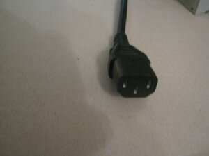
To do this, check network cable from the plug to the plug of the cord, photo # 1, for the integrity of the wiring, the check is carried out with a "multimeter" device.
It is necessary to further check for resistance electrical circuit from the contacts of the switch socket to the power supply of the circuit.
The picture of photo # 2 clearly shows the supply of power to the circuit, the third wire from the socket goes to the ground of the switch case. This circuit is a voltage converter:
- input voltage - 220V;
- output voltage - 3.3V.
The input voltage current, as usual for a household external source, is - 10 amperes. The current for the output voltage of the converter is 4 amperes. The voltage converter, in turn, feeds the elements of the microcircuit and then the signal is distributed over the portals.
The third photo shows a circuit that receives power from a voltage converter.
The reasons for the malfunction here can be varied and require a check of all electronic elements. In particular, in my practice, such a cause of the malfunction was the failure of the electronic elements of the voltage converter photo No. 2. Lost their conductivity - resistance and two transistors. Replacing such elements is a painstaking task and requires certain skills. When soldering new parts, others can be damaged. Therefore, with your uncertainty in carrying out such a delicate work, it is easier to contact the specialist himself directly.
Currently, the widespread model of the GAZ-2705 GAZelle car is equipped with a contactless battery ignition system with an electronic switch 13.3734-01.
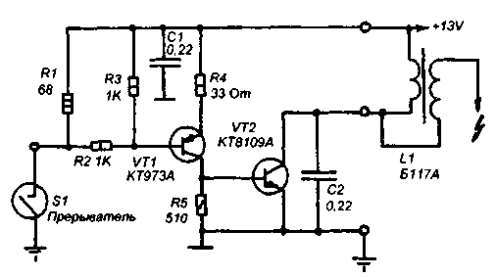
The schematic diagram of the electronic switch 13.3734-01 is shown in the figure. The switch elements are located on a printed circuit board, which is mounted inside a metal case, which is a cooling radiator for the output transistor VT2.
The elements of the switch circuit operate in a severe thermal regime under conditions of voltage and current fluctuations in the vehicle's on-board network.
Usually, switch malfunctions are associated with the failure of either the terminal transistor VT2 or the input diode VD2, which is easy to determine using an ohmmeter. For a more detailed check of the input circuits of the switch, it is necessary to apply voltage + (12… 13) V to the “+” contact from a stabilized power supply. A sinusoidal signal with an amplitude of 12 V and a frequency of 40 ... 80 Hz is supplied to the contact "D" from the generator of standard signals.
Rice. 2 Schematic diagram of an electronic switch
The oscilloscope controls the signal flow at the following points: the cathode of the diode VD3, the collector of the transistor VT1 and the pin.14 microcircuits DA1. When repairing an electronic switch, in which the output transistor is broken, along with its replacement, it is advisable to replace the insulating mica gasket under its case measuring 18 x 23 mm and 0.21 mm thick with a gasket 0.1 mm thick. This will not affect the reliability of the switch, but will improve the process of heat removal from the output transistor.
To replace the VT2 transistor, you can use semiconductor devices KT898A, KT8109A, KT8117A, which are similar in parameters, and are specially designed to work in automotive ignition systems.
- Alexey / 09/14/2018 - 14:28
Bitter to read! Guys, did they teach you Russian? Where is this taught? At first glance, you have a grade 1 education and a corridor! Shame and disgrace! You need to know your native language not only spoken, but also written! Learn before it's too late! - Ed / 07/25/2017 - 07:20
should be from the VT1 collector goes to the R7 C4 connection and to the 5th pin of the microcircuit, R7 the upper end to the right R8 pin. - zhorik / 12/14/2015 - 10:19
Why does the UAZ hunter car stall after heating on the move like there is no current, the starter turns great, but does not start after a day or a couple of hours - nnn / 08/23/2015 - 11:27
commutator on the diagram 131 and not 13 3734 - Anatoly / 04/07/2014 - 07:33
Ana, how often does the k1055HP1 chip fly out? —– Well, it's hard to predict .. It mainly depends on the quality of workmanship. and If you do not violate the mode of the microcircuit, But the electronics has its own duty cycle. as well as the pac bulb. Anatoly. - Pavel / 05/20/2013 - 13:16
why is the ignition coil warming up even though everything has changed: coil switch - Anatoly / 02/14/2013 - 18:35
Kind time of day, everyone. I have a question of this order, but has anyone tried to connect instead of the sensor to the switch input 13.3774-01, the native contacts of the distributor? —So the camutator will not work for a long time .. will sigh. this time and the second zboy ignition. will trait. tested on Zhiguli. - Olezha / 02/14/2013 - 18:24
why are the "runners" burning in the contactless system. Coil B-116, tr. 131 3734. — Look at the tramler cover, it may be the fault of the crack. - Anatolij / 02/14/2013 - 06:46
dear! maybe YOU can tell me WHERE to find such "lectures" on a slightly different switch 12.3774 (analogue 3660.3737, 13.3734). nowhere can I find any schemes or comments. I will be extremely grateful (Well, vaabsche then, in principle, the differences between them do not have the same principle in work. The camutator is the electronic key. The difference between them is the wiring of the connector of the camutator itself .. The current outputs are power + and - output to the coil of the ignition coil and ( D) the cottager goes to the tramler, there are summer cottages called (holom) they need food + also - and the third output is (D) which goes to the camutator, this is the control of the camutator, On the tramler itself, there are three outputs, which in the middle are and eats exit (D), that is, a dachik. If a bayats wolf, then do not go to the forest - Anatoly / 02/14/2013 - 05:43
I was surprised by R7 Why is he. (This is just a typo or error. T1 is just a key and R7 is not needed there. - Anatoly / 02/14/2013 - 05:28
but which one is better to replace the KT 837 x transistor? (Look at the manual. Pay attention to the current and voltage, they must be high-voltage. The lower the voltage, the less chances for the transistor to survive. The reference data can be found in the internet. - Anatoly / 02/14/2013 - 05:11
Thank you all. And there is electrolyte or not near R7. Who knows. (Steam it yourself, there will be a positive or negative result, also a result. And finally, saber a simple stent without a tramler. (Kamutator and babin). that is, on the Masu). Well, in the past, you will understand my log— —– = - = - Anatolij. - Anatoly / 02/14/2013 - 05:09
Thank you all. And there is electrolyte or not near R7. Who knows. (Steam it yourself, there will be a positive or negative result, also a result. And finally, saber a simple stent without a tramler. (Kamutator and babin). that is, on the Masu). Well, in the past, you will understand my log— —– = - = - Anatolij. - Vasily / 11/18/2012 - 08:27
why are the "runners" burning in the contactless system. Coil B-116, tr. 131 3734. - Pramjeet / 03/23/2012 - 04:34
I'm not wrohty to be in the same forum. ROTFL - Vladimir / 03/22/2012 - 17:09
Kind time of day, everyone. I have a question of this order, but has anyone tried to connect, instead of a sensor, to the switch input 13.3774-01, the distributor's own contacts? - hiio / 26.02.2012 - 20:28
ATTENTION ALL. SEVERE ERRORS FOUND IN THE DIAGRAM OF THE SWITCH 13.3734-01 IN THE PICTURE WHAT SHOULD BE CHANGED TO MAKE THE SCHEME IN ACCORDANCE WITH THE FACTORY ASSEMBLY: 1) UPPER END OF RESISTOR R7 AND UPPER END OF C5 CAPACITOR SHOULD BE CONNECTED TO THE 3RD FEET OF THE MICRO. 2) REAL NOMINALS OF C7 AND C8 CAPACITORS - PER 2.2 MKF. (THE PICTURE SHOWS THE VALUE OF THEIR NOMINAL IN 22MKF.) ALL SUCCESS. - Alexander / 23.01.2012 - 19:02
There is a DIODE! - Kinap / 08/19/2011 - 05:20
Ana, how often does the k1055HP1 chip fly out? - Kinap / 08/19/2011 - 05:17
And how often does the k1055xp1 chip fly out?
12Forward
You can leave your comment, opinion or question on the above material:
Switches are actively used to create a local network, its decentralized segments. The most common switches are Edge-Core, D-Link, FoxGate, Zyxel, TP-Link. For switches, repair is an opportunity to restore their functionality after failure. Any switch failure can shut down the entire office.
Network equipment is very sensitive to various kinds of external factors. Breakdowns of switches occur for the following reasons:
- A sharp increase in the voltage in the network. Thunderstorms are especially dangerous for the switch, causing even minor changes.
- Mechanical damage. Hitting the switch chassis will damage chips and systems. They can be caused both by falling of the equipment itself, and by hitting it with heavy objects.
- Sloppy operation. Pulling the cable, spilling liquid, or other factors related to user actions can damage the ports and internal components of the switch.
- Software crashes. This leads to permanent disruptions in the operation of the entire local network.
Switch repair: what most often fails?
Preliminary diagnostics allows you to determine the causes of the switch malfunction, only after that you can build a repair plan. The most common breakdowns include:
- damage to the memory card integrated into the switch;
- deformation of the network ports, damage to the legs;
- burnout of electronic components, microcircuits;
- malfunctions of power supplies;
- violations in the firmware;
- constant overheating of the switch;
- incorrect settings causing constant conflicts on the network.
Repair of this equipment requires special skills and knowledge; it is almost impossible to carry out it yourself.
Network equipment repair methods
Repairing a switch requires detailed, correct diagnostics, which will allow you to determine the feasibility of performing subsequent actions. In some cases, the problem is caused by a freeze in the hardware, which can be dealt with by a simple reboot. The possible methods for restoring the operation of the switch are as follows:
- Hardware firmware. One of the easiest ways to get the switch back working. To do this, you need to have an up-to-date, working version of the software, special recording equipment.
- Correction of the defect that has arisen. In this case, soldering of the detached metal elements is used.
- Replacement of a failed part. In this case, it is necessary to estimate the cost of repair work, purchase of a new spare part. In some cases, with significant damage, it is more advisable to buy a new switch.
Features of the repair work
To restore the switch, the foreman must have the necessary knowledge, skills, technical and physical means to provide the service. For this reason, it is advisable to contact specialized service centers that will perform the necessary actions. The work consists of the following stages:
- Diagnostics. It is necessary to determine the cause of violations in the local network (in some cases, the switch turns out to be working, problems may arise with cables, incorrect configuration). If the lack of communication is caused by a breakdown of the switch, the master is obliged to determine which element is out of order.
- Draw up an action plan. This is required for the subsequent determination of the cost of work, the list of necessary spare parts, and their prices.
- Coordinate the execution of work with the customer. To do this, he needs to describe the essence of the problem, ways to solve it, the cost of the proposed and alternative methods, and possible risks.
- Performing the necessary actions to restore the functionality of the switch.
Fast restoration of the switch will minimize office downtime, so you should contact only trusted companies working in the field of IT technologies.
The ignition switch is available on every car, regardless of model and year of manufacture. Devices can be divided into separate types, but the principle of their operation remains approximately the same. But not every car enthusiast knows what it is, and what function a regular switch performs, without which it would be impossible to start the engine and get under way.
This simple electronic device only performs the function of sparking. But failures in its operation can lead to instability of the engine at idle or in other operating modes of the unit. Sometimes they start looking for a problem in the engine systems instead of figuring out whether the electrical impulse of the ignition system switch is being formed correctly.
You can check its work both in the service and at home. True, in the second case, you will have to purchase or make yourself a special device. But there will always be a device at hand with which it will be possible to determine the cause of the difficult ignition or other common problems in the operation of the car.
This buzzword, in fact, means a primitively simple device. It is responsible for sparking in the ignition system. The moment of sparking is carried out in the ignition unit. And the switch is the small electronic device that controls the unit.
For better understanding, any ignition system is divided into two main parts - a control system and a spark discharge system. The control system forms the moment the spark appears, and the execution system directly forms this spark. This article will focus specifically on spark control in the ignition system. But in order to understand a little about its functions, you should recall some moments from automotive history.
Video what a switch is:
The first cars were equipped with the simplest control units for the ignition system. A diagram of their work is shown below.
This circuit uses the principle of self-induction. The rupture of the current flow circuit in the bobbin winding is accompanied by a secondary high-voltage EMF. In this case, a spark appears on the contact of the candle. The circuit is broken by closing the contacts on the breaker.
This ignition switch circuit is simple and reliable, therefore it was installed on cars for a long time, despite its obvious shortcomings. Even after changing the elementary base, the original principle of operation of the device has been preserved.
The main disadvantage of such a system is the too high current flowing through the coil. As a result - the appearance of sparking in the breaker, its melting and burning of the contacts. To this should be added the short duration of the spark discharge.As a result, for a full-fledged ignition, a more enriched combustible mixture is required, poor engine throttle response appears at low speeds, and fuel consumption increases.
But over time, the automotive industry reached a new level, and electronic ignition switches began to be used in ignition systems.
The work of the new generation ignition switch is based on the use of electronic keys. They are used transistors VT1 and VT2. Their use reduces the load on the breaker contact and increases the current that flows through the coil winding. As a result of this decision, the characteristics of the device have increased:
- increased system reliability;
- the system can now operate at high engine speeds and at significant travel speeds;
- the compression ratio has increased.
Electronic systems can be of the following types:
- transistor, their circuit is shown below;
- thyristor, characterized by the accumulation of energy in a capacitor instead of an electromagnetic ignition coil;
- hybrid with cams;
- contactless, they are used in the vast majority of modern cars.
To achieve high levels of reliability and performance, two-channel systems are used. And also - multichannel, or multi-spark switches.
They should be disassembled in a little more detail. The cam switch system shown above uses a cam switch and an electronic switch with a coil. The use of electronic ignition elements significantly increases the efficiency of this device and increases its reliability. Instead of a Hall sensor, cams are connected to the commutator. You can also connect them with your own hands.
The convenience of using this circuit is characterized by the fact that if the switch fails, you can switch the wires to the old coil and then you can go on cam ignition.
With the introduction of electronic devices into the ignition system, auto manufacturers over time began to abandon contact switches. Voltage breakers began to be replaced by proximity sensors. How does such a switch work? Quite simply, the device now receives signals from a node called a Hall sensor. By the way, on domestic cars, contactless switches were first used for the VAZ 2108.
When using the sensors, interruptions in sparking disappeared, the error between the moment of ignition of the combustible mixture in the right and left cylinders decreased. But the problem of finding the optimal dependence of the ignition timing on the speed of the unit has not gone anywhere. This problem was helped to eliminate the switch with an advanced ignition angle with a microcontroller system.
In them, the signal from the electronic sensor is fed to input X1. In this device, signal processing is performed by a microcontroller, which determines the moment when the coil is turned on and off. Its commutation is determined by transistor switches that control the signal of the controller. As a result, the lead angle graph looks like this:
You can also make a two-channel switch with your own hands. You don't need to have an in-depth knowledge of electrical engineering or be a good mechanic to do this. But minor amendments to the ignition system will ensure its smooth operation in various driving conditions. Single-pin switches are outdated for a long time. And the converted version will immediately allow you to feel its advantages. So, you will need to perform the following procedure:
- remove the distributor cover;
- turn off the high-voltage drive from the coil;
- using the starter, we set the resistor perpendicular to the unit;
- make a mark on the distributor and the engine where it coincides with the middle of the distributor;
- remove the old distributor, after unscrewing the fasteners;
- turn off the drive from the coil to the distributor;
- we take a new distributor, remove the cover from it and install it on the engine according to the label;
- we fix the mounting plug, put on the cover with the drives;
- change the coil to a new one and connect the wires to it;
- the engine can now be started.
Of course, the procedure will take some time, because many actions will be related to the car's electrical system. But a two-channel ignition switch will make it easier to start the car, and at the same time - save fuel and maintain engine resources.
Despite the clear advantages of newer switches, they have one drawback: it is more difficult to identify a problem in their operation than in the case of single-pin devices. This problem especially concerns those drivers who have installed new switches on their car. As a rule, faults in two-pin or electronic switches can be detected only in the conditions of specialized service centers. But you should also pay attention to obvious signs in the operation of ignition systems:
- the engine does not start, there is no spark on the spark plugs;
- the unit stalls a few minutes after it starts up;
- unstable engine operation.
If at least one of these signs is observed, then it is worth replacing the device with a serviceable one.
Also, the serviceability of the device can be checked using a voltmeter. When the ignition is turned on, the arrow should be in the middle of the scale. Then it will swing to the right when the power is turned off. These indicators of the device will indicate the normal operation of the switch.
You can also use a homemade switch tester. It is a control lamp that can be easily made by hand. One end of the lamp is connected to ground, the other to the output of the coil. If the ignition is turned on, then if the device is working properly, after a short period of time, the lamp will burn a little brighter.
Since, after all, an idea appeared on the Internet about the possibility of using the switch 3620.3734 * instead of the standard Tavrian 1102.3734 / 1103.3734, I decided to post an article on repairing these, at the same time in conjunction with the circuits of these switches. The original article is here, but for some reason the developer of this web page posted pictures separately from the article. Very inconvenient, I shift it humanly means:
If the electronic ignition switch in your car fails, as a rule, you either buy a new one, since there is no way to test it for operability due to the lack of specialized service centers, or you bring it to local craftsmen who try it by "scientific poke" to repair. Most of the operating instructions do not contain a description of the troubleshooting method, therefore we present a complete troubleshooting method and schematic diagrams of the most common electronic ignition switches.
Ignition systems for gasoline engines of domestic passenger cars VAZ-2108, VAZ-2109, ZAZ-1102 contain an electronic switch. It is designed to generate current pulses in the primary circuit of the ignition coil.
In electronic switches of domestic production (series 3620.3734; 36.3734; 78.3734), the functions of the output current switch are performed by a powerful transistor, and the functions of controlling the parameters of current pulses (normalizing the duty cycle of starting pulses, programmed regulation of the time of accumulation of energy in the ignition coil, limiting the current level in its primary winding and amplitudes of pulses of primary voltage) is performed by a low-current electronic circuit, more often in an integrated version.
The first domestic electronic switch with controlled parameters of ignition pulses (series 36.3734) was developed for the VAZ-2108 car. The switch used a K1401UD1 microcircuit, a powerful key transistor KT848A and other elements of domestic production.
The input information signal for the commutator is the signal from the Hall sensor located on the ignition distributor shaft.According to this signal, the switch receives information about the number of engine revolutions and the position of its crankshaft. The switch is designed to work with a serial ignition coil 27.3705. The switch served as a prototype for the development of subsequent series, which have several options for design and circuit design. However, the combined integral-discrete assembly technology, which makes them maintainable, is still common to domestic switches.
In modern domestic switches, specialized output key transistors of the types KT890A, KT898A1, BU931 (foreign) are used in several designs: TO-220, TO-3, without package. In some switches, for example 78.3734 (Fig. 4), a four-channel operational amplifier of the K1401UD2B type is used as a control microcircuit.
The switches also widely use the SGS-TOMSON L497B control microcircuit (domestic analogue Р1055ХП1). The block diagram and the recommended option for its inclusion are shown in Fig. 1, and the purpose of the conclusions is in table. one.
If with some malfunctions on the car you can somehow get to the repair point, then with a faulty switch, the engine will not start at all. Some drivers often carry a spare switch with them. In this article, we will consider the principle of operation, some malfunctions of the automotive switch and how to repair it.
- Often the switch breaks down due to water ingress into it. As a result, the kr1055hp4 microcircuit (analogue of L497B) fails,
- Due to overvoltage or from time to time, the output transistor of the type KT8231A1, KT8225A, KT8232A1, KTD8252A, KTD8264A, KTD8267, KT898A, KT8127A1 (analogue of BU941ZP) often fails.
To test the switch, we assemble such a simple stand as in the figure below. We connect a 12 V light bulb instead of a coil.
When we turn the axle of the distributor with the DH (hall sensor), the light comes on. When we do not turn and the light does not light up.
The Hall sensor is a magnetoelectric device that got its name from the surname of the physicist Hall, who discovered the principle on the basis of which this sensor was later created. Simply put, it is a magnetic field sensor. There are two types of Hall sensors: analog and digital.
Analog Hall sensors - convert the field induction into voltage, the value shown by the sensor depends on the polarity of the field and its strength. But again, you need to consider the distance at which the sensor is installed.
Digital sensors detect the presence or absence of a field. That is, if the induction reaches a certain threshold - the sensor gives out the presence of the field in the form of a certain logical unit, if the threshold is not reached - the sensor gives out a logical zero. That is, with a weak induction and, accordingly, the sensitivity of the sensor, the presence of a field may not be detected. The disadvantage of such a sensor is the presence of a dead zone between the thresholds.
Digital Hall sensors are also divided into: bipolar and unipolar.
Unipolar - they work in the presence of a field of a certain polarity and turn off when the field induction decreases.
Bipolar - they react to a change in the polarity of the field, that is, one polarity turns on the sensor, the other turns it off.
- Measure the voltage at the sensor output. It must be more than 0.4 V.
- Check for a spark when the ignition is turned on. To do this, you need to close the 1 and 2 output of the switch with a wire.
- Replace with a known good one.
Some switches have a different "logic" output. Some, for example 131.3734-01 - have a logical "1", while others have a "0". Who has "1" by default (this is when the device shows 12 volts or close to them by default between the contacts "+" and "short circuit") actually run the risk of burning the coil at the moment when the ignition is turned on and the engine does not work, creating a one-sided potential inside the coil and without discharging it, thereby you can feel the rapid heating of the coil with your hand. The created potential begins to discharge only when the engine is running. The advantage of such switches is that you can use conventional (native) coils for contact ignition practically without disturbing the old coil connection circuit.The switch in this case is inserted into the wire break from which went from the breaker contact to the coil. The Trambler is simply replaced and a switch is added.
In the switch, for example BSZ 131.3734, the default logic "0" is observed. If with the coil of the switch kit 131 3734 you put it with logic "1" by default, then the coil will be terribly hot. Or, on the contrary, on the coil intended for a switch with logic "1", put switch 131 3734 - logic "0", then either there will be no spark, or it will be very weak, or you can even damage the switch.
In recent years, electronic devices are increasingly used in road transport, including electronic ignition devices. The progress of automobile carburetor engines is inextricably linked with their further improvement. In addition, new requirements are now imposed on ignition devices aimed at a radical increase in reliability, fuel efficiency and environmental cleanliness of the engine. More details ...
For sounding children's toys, motorcycles and battery-powered cars, I suggest you make a simple circuit of a sound device that simulates the "Police siren" signal. The circuit is simple, contains few details and does not require any configuration. It is not difficult to assemble it, especially if you order flashed microcontrollers from the link at the end of the article.
Often, when the car does not start, what kind of torment doesn’t have to endure in order to reanimate the iron horse. Well, if the problem lies in candles or sour sockets in the wiring connections, then the malfunction is quickly localized. But it also happens that the structural elements of the ignition system fail. Quite often, the culprit of an unpleasant "celebration" is the VAZ 2108 switch. In the latter case, the skills of self-checking the operation of the device, a general understanding of the principle of its operation and a visual electrical diagram will not be superfluous.
This element in the operation of a car is an electronic unit that, by perceiving signals from a special magnetic induction sensor (aka Hall sensor), controls the operation of the ignition system. The schematic diagram of the device will not bother us too much, because if a switch breaks down, it is simply changed to a new one, it is much more important to understand how it works and, most importantly, how to diagnose it if necessary. But first things first.
The VAZ 2108 switch is connected directly to the ignition key, through which it is powered from the automotive electrical network. The scheme of operation of the device also assumes direct electrical connection with the ignition coil and the spark ignition distributor. The task of the car switch is to regulate the operation of car candles through the ignition distributor using the control signals from the sensor.
The simplest way, of course, would be to check a banal replacement for a known working unit, but there are other, more sophisticated options. To do this, you need either a voltage meter with a limit of up to 20 V (for example, a multimeter), or a control lamp for 12 V. After that, you must perform the following procedure:
- 1. Find the ignition coil under the hood of the car and disconnect the terminal marked with the letter “K” from it. This conductor is directly connected to the first pin on the switch.
- 2. In the resulting break in the electrical circuit, connect a test lamp or a device that measures a constant electric voltage with a limit of up to 20 V.
- 3.To carry out the check, it will be necessary to turn the ignition key by turning the engine with an auto starter. As a result of diagnostics, the light should blink, and the multimeter should show voltage changes.

