In detail: do-it-yourself repair of ignition switches from a real master for the site my.housecope.com.
Ignition systems for gasoline engines of domestic passenger cars VAZ-2108, VAZ-2109, ZAZ-1102 contain an electronic switch. It is designed to generate current pulses in the primary circuit of the ignition coil.
In electronic switches of domestic production (series 3620.3734; 36.3734; 78.3734), the functions of the output current switch are performed by a powerful transistor, and the functions of controlling the parameters of current pulses (normalizing the duty cycle of starting pulses, programmed regulation of the time of accumulation of energy in the ignition coil, limiting the current level in its primary winding and amplitudes of pulses of primary voltage) is performed by a low-current electronic circuit, more often in an integrated version.
The first domestic electronic switch with controlled parameters of ignition pulses (series 36.3734) was developed for the VAZ-2108 car. The switch used a K1401UD1 microcircuit, a powerful key transistor KT848A and other elements of domestic production.
The input information signal for the commutator is the signal from the Hall sensor located on the ignition distributor shaft. According to this signal, the switch receives information about the number of engine revolutions and the position of its crankshaft. The switch is designed to work with a serial ignition coil 27.3705.
The switch served as a prototype for the development of subsequent series, which have several design and circuit design options. However, the combined integrated-discrete assembly technology, which makes them maintainable, is still common to domestic switches.
| Video (click to play). |
In modern domestic switches, specialized output key transistors of the types KT890A, KT898A1, BU931 (foreign) are used in several designs: TO-220, TO-3, without package. In some switches, for example 78.3734 (Fig. 4), a four-channel operational amplifier of the K1401UD2B type is used as a control microcircuit.
The switches also widely use the SGS-TOMSON L497B control microcircuit (domestic analogue Р1055ХП1). The block diagram and the recommended option for its inclusion are shown in Fig. 1, and the purpose of the conclusions is in table. one.
Before you start troubleshooting and repairing the electronic switch, you should:
• check the integrity of the car wiring, the reliability of the contact connections of the ignition system, the serviceability of the elements of the ignition system (plugs, ignition coil, Hall sensor, high voltage wires);
• check the serviceability of the car generator, as well as its integral voltage regulator;
• check the supply of voltage from the on-board network (with the ignition switch turned on) to the contact "P" of the Hall sensor connector.
The signs by which malfunctions of electronic switches are manifested, the most probable causes of these malfunctions and ways to eliminate them are summarized in Table. 2.
The basic electrical circuits of the ignition switches are shown in Fig. 2 (switch 3620.3734 - I), Fig. 3 (switch 3620.3734 - II) and Fig. 4 (switch 78.3734).
In conclusion, the following should be noted:
1. A close analogue of the foreign transistor BU931 (see diagrams in Fig. 2 and 3) is the domestic KT898A1. These transistors have a wide range of parameters, which leads to the need to select the ratings of radioelements in its base and emitter circuits, for each transistor separately.
2. Resistors R7 (see fig. 2) and R6 (see fig.3) serve to set the required current value through the powerful key transistors of the described switches.
An increase in the value of the resistors leads to a decrease in the current and vice versa.
Thus, by changing the values of these resistors, you can select the optimal current and thermal modes of operation of the output key transistors.
3. When replacing a powerful key transistor, you should pay attention to the quality of attachment of the transistor to the heat sink (case) of the switch. Also check for the presence of heat-conducting paste between the transistor and the radiator (switch case).
4. An analogue of the foreign zener diode 1N3029 (see Fig. 3) is the domestic KS524.
5. An analogue of the foreign microcircuit L497B (see Fig. 1, 2, 3) is the domestic KR1055HP1.
6. After replacing faulty radio elements in the switch, each new element on the board and the place of its soldering should be covered with nitro varnish. When assembling the switch case, coat the cover around the perimeter of the seal with a waterproof sealant (for example, "Hermesil").
The ignition switch is available on every car, regardless of model and year of manufacture. Devices can be divided into separate types, but the principle of their operation remains approximately the same. But not every car enthusiast knows what it is, and what function a regular switch performs, without which it would be impossible to start the engine and get under way.
This simple electronic device only performs the function of sparking. But failures in its operation can lead to instability of the engine at idle or in other operating modes of the unit. Sometimes they start looking for a problem in the engine systems instead of figuring out whether the electrical impulse of the ignition system switch is being formed correctly.
You can check its work both in the service and at home. True, in the second case, you will have to purchase or make yourself a special device. But there will always be a device at hand with which it will be possible to determine the cause of the difficult ignition or other common problems in the operation of the car.
This buzzword, in fact, means a primitively simple device. It is responsible for sparking in the ignition system. The moment of sparking is carried out in the ignition unit. And the switch is the small electronic device that controls the unit.
For better understanding, any ignition system is divided into two main parts - a control system and a spark discharge system. The control system forms the moment the spark appears, and the execution system directly forms this spark. This article will focus specifically on spark control in the ignition system. But in order to understand a little about its functions, you should recall some moments from automotive history.
Video what a switch is:
The first cars were equipped with the simplest control units for the ignition system. A diagram of their work is shown below.
This circuit uses the principle of self-induction. The rupture of the current flow circuit in the bobbin winding is accompanied by a secondary high-voltage EMF. In this case, a spark appears on the contact of the candle. The circuit is broken by closing the contacts on the breaker.
This ignition switch circuit is simple and reliable, therefore it was installed on cars for a long time, despite its obvious shortcomings. Even after changing the elementary base, the original principle of operation of the device has been preserved.
The main disadvantage of such a system is the too high current flowing through the coil. As a result - the appearance of sparking in the breaker, its melting and burning of the contacts. To this should be added the short duration of the spark discharge. As a result, for a full-fledged ignition, a more enriched combustible mixture is required, poor engine throttle response appears at low speeds, and fuel consumption increases.
But over time, the automotive industry reached a new level, and electronic ignition switches began to be used in ignition systems.
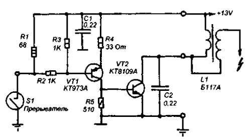
The work of the new generation ignition switch is based on the use of electronic keys. In their capacity, transistors VT1 and VT2 are used. Their use reduces the load on the breaker contact and increases the current that flows through the coil winding. As a result of this decision, the characteristics of the device have increased:
- increased system reliability;
- the system can now operate at high engine speeds and at significant travel speeds;
- the compression ratio has increased.
Electronic systems can be of the following types:
- transistor, their circuit is shown below;
- thyristor, characterized by the accumulation of energy in a capacitor instead of an electromagnetic ignition coil;
- hybrid with cams;
- contactless, they are used in the vast majority of modern cars.
To achieve high levels of reliability and performance, two-channel systems are used. And also - multichannel, or multi-spark switches.
They should be disassembled in a little more detail. The cam switch system shown above uses a cam switch and an electronic switch with a coil. The use of electronic ignition elements significantly increases the efficiency of this device and increases its reliability. Instead of a Hall sensor, cams are connected to the commutator. You can also connect them with your own hands.
The convenience of using this circuit is characterized by the fact that if the switch fails, you can switch the wires to the old coil and then you can go on cam ignition.
With the introduction of electronic devices into the ignition system, auto manufacturers over time began to abandon contact switches. Voltage breakers began to be replaced by proximity sensors. How does such a switch work? Quite simply, the device now receives signals from a node called a Hall sensor. By the way, on domestic cars, contactless switches were first used for the VAZ 2108.
When using the sensors, interruptions in sparking disappeared, the error between the moment of ignition of the combustible mixture in the right and left cylinders decreased. But the problem of finding the optimal dependence of the ignition timing on the speed of the unit has not gone anywhere. This problem was helped to eliminate the switch with an advanced ignition angle with a microcontroller system.
In them, the signal from the electronic sensor is fed to input X1. In this device, signal processing is performed by a microcontroller, which determines the moment when the coil is turned on and off. Its commutation is determined by transistor switches that control the signal of the controller. As a result, the lead angle graph looks like this:
You can also make a two-channel switch with your own hands. You don't need to have an in-depth knowledge of electrical engineering or be a good mechanic to do this. But minor amendments to the ignition system will ensure its smooth operation in various driving conditions. Single-pin switches are outdated for a long time. And the converted version will immediately allow you to feel its advantages. So, you will need to perform the following procedure:
- remove the distributor cover;
- turn off the high-voltage drive from the coil;
- using the starter, we set the resistor perpendicular to the unit;
- make a mark on the distributor and the engine where it coincides with the middle of the distributor;
- we remove the old distributor, having previously unscrewed the fasteners;
- turn off the drive from the coil to the distributor;
- we take a new distributor, remove the cover from it and install it on the engine according to the label;
- we fix the mounting plug, put on the cover with the drives;
- change the coil to a new one and connect the wires to it;
- the engine can now be started.
Of course, the procedure will take some time, because many actions will be related to the car's electrical system.But a two-channel ignition switch will make it easier to start the car, and at the same time - save fuel and maintain engine resources.
Despite the clear advantages of newer switches, they have one drawback: it is more difficult to identify a problem in their operation than in the case of single-pin devices. This problem especially concerns those drivers who have installed new switches on their car. As a rule, faults in two-pin or electronic switches can be detected only in the conditions of specialized service centers. But you should also pay attention to obvious signs in the operation of ignition systems:
- the engine does not start, there is no spark on the spark plugs;
- the unit stalls a few minutes after it starts up;
- unstable engine operation.
If at least one of these signs is observed, then it is worth replacing the device with a serviceable one.
Also, the serviceability of the device can be checked using a voltmeter. When the ignition is turned on, the arrow should be in the middle of the scale. Then it will swing to the right when the power is turned off. These indicators of the device will indicate the normal operation of the switch.
You can also use a homemade switch tester. It is a control lamp that can be easily made by hand. One end of the lamp is connected to ground, the other to the output of the coil. If the ignition is turned on, then if the device is working properly, after a short period of time, the lamp will burn a little brighter.
Currently, the widespread model of the GAZ-2705 GAZelle car is equipped with a contactless battery ignition system with an electronic switch 13.3734-01.
The schematic diagram of the electronic switch 13.3734-01 is shown in the figure. The switch elements are located on a printed circuit board, which is mounted inside a metal case, which is a cooling radiator for the output transistor VT2.
The elements of the switch circuit operate in a severe thermal regime under conditions of voltage and current fluctuations in the vehicle's on-board network.
Usually, switch malfunctions are associated with the failure of either the terminal transistor VT2 or the input diode VD2, which is easy to determine using an ohmmeter. For a more detailed check of the input circuits of the switch, it is necessary to apply voltage + (12… 13) V to the “+” contact from a stabilized power supply. A sinusoidal signal with an amplitude of 12 V and a frequency of 40 ... 80 Hz is supplied to the contact "D" from the generator of standard signals.
Rice. 2 Schematic diagram of an electronic switch
The oscilloscope controls the signal flow at the following points: the cathode of the VD3 diode, the collector of the VT1 transistor and the pin. 14 microcircuits DA1. When repairing an electronic switch, in which the output transistor is broken, along with its replacement, it is advisable to replace the insulating mica gasket under its case measuring 18 x 23 mm and 0.21 mm thick with a gasket 0.1 mm thick. This will not affect the reliability of the switch, but will improve the process of heat removal from the output transistor.
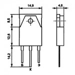
To replace the VT2 transistor, you can use semiconductor devices KT898A, KT8109A, KT8117A, which are similar in parameters, and are specially designed to work in automotive ignition systems.
- Alexey / 09/14/2018 - 14:28
Bitter to read! Guys, did they teach you Russian? Where is this taught? At first glance, you have a grade 1 education and a corridor! Shame and disgrace! You need to know your native language not only spoken, but also written! Learn before it's too late! - Ed / 07/25/2017 - 07:20
should be from the VT1 collector goes to the R7 C4 connection and to the 5th pin of the microcircuit, R7 the upper end to the right R8 pin. - zhorik / 12/14/2015 - 10:19
Why does the UAZ hunter car stall after heating on the move like there is no current, the starter turns great, but does not start after a day or a couple of hours - nnn / 08/23/2015 - 11:27
commutator on the diagram 131 and not 13 3734 - Anatoly / 04/07/2014 - 07:33
Ana, how often does the k1055HP1 chip fly out? —– Well, it's hard to predict .. It mainly depends on the quality of workmanship. and If you do not violate the mode of the microcircuit, But the electronics has its own duty cycle. as well as the pac bulb. Anatoly. - Pavel / 05/20/2013 - 13:16
why is the ignition coil warming up even though everything has changed: coil switch - Anatoly / 02/14/2013 - 18:35
Kind time of day, everyone. I have a question of this order, but has anyone tried to connect instead of the sensor to the switch input 13.3774-01, the native contacts of the distributor? —So the camutator will not work for a long time .. will sigh. this time and the second zboy ignition. will trait. tested on Zhiguli. - Olezha / 02/14/2013 - 18:24
why are the "runners" burning in the contactless system. Coil B-116, tr. 131 3734. — Look at the tramler cover, it may be the fault of the crack. - Anatolij / 02/14/2013 - 06:46
dear! maybe YOU can tell me WHERE to find such "lectures" on a slightly different switch 12.3774 (analogue 3660.3737, 13.3734). nowhere can I find any schemes or comments. I will be extremely grateful (Well, vaabsche then, in principle, the differences between them do not have the same principle in work. The camutator is the electronic key. The difference between them is the wiring of the connector of the camutator itself .. The current outputs are power + and - output to the coil of the ignition coil and ( D) the cottager goes to the tramler, there are summer cottages called (holom) they need food + also - and the third output is (D) which goes to the camutator, this is the control of the camutator, On the tramler itself, there are three outputs, which in the middle are and eats exit (D), that is, a dachik. If a bayats wolf, then do not go to the forest - Anatoly / 02/14/2013 - 05:43
I was surprised by R7 Why is he. (This is just a typo or error. T1 is just a key and R7 is not needed there. - Anatoly / 02/14/2013 - 05:28
but which one is better to replace the KT 837 x transistor? (Look at the manual. Pay attention to the current and voltage, they must be high-voltage. The lower the voltage, the less chances for the transistor to survive. The reference data can be found in the internet. - Anatoly / 02/14/2013 - 05:11
Thank you all. And there is electrolyte or not near R7. Who knows. (Steam it yourself, there will be a positive or negative result, also a result. And finally, saber a simple stent without a tramler. (Kamutator and babin). that is, on the Masu). Well, in the past, you will understand my log— —– = - = - Anatolij. - Anatoly / 02/14/2013 - 05:09
Thank you all. And there is electrolyte or not near R7. Who knows. (Steam it yourself, there will be a positive or negative result, also a result. And finally, saber a simple stent without a tramler. (Kamutator and babin). that is, on the Masu). Well, in the past, you will understand my log— —– = - = - Anatolij. - Vasily / 11/18/2012 - 08:27
why are the "runners" burning in the contactless system. Coil B-116, tr. 131 3734. - Pramjeet / 03.23.2012 - 04:34
I'm not wrohty to be in the same forum. ROTFL - Vladimir / 03/22/2012 - 17:09
Kind time of day, everyone. I have a question of this order, but has anyone tried to connect, instead of a sensor, to the switch input 13.3774-01, the distributor's own contacts? - hiio / 26.02.2012 - 20:28
ATTENTION ALL. SEVERE ERRORS FOUND IN THE DIAGRAM OF THE SWITCH 13.3734-01 IN THE PICTURE WHAT SHOULD BE CHANGED TO MAKE THE SCHEME IN ACCORDANCE WITH THE FACTORY ASSEMBLY: 1) UPPER END OF RESISTOR R7 AND UPPER END OF C5 CAPACITOR SHOULD BE CONNECTED TO THE 3RD FEET OF THE MICRO. 2) REAL NOMINALS OF C7 AND C8 CAPACITORS - PER 2.2 MKF. (THE PICTURE SHOWS THE VALUE OF THEIR NOMINAL IN 22MKF.) ALL SUCCESS. - Alexander / 23.01.2012 - 19:02
There is a DIODE! - Kinap / 08/19/2011 - 05:20
Ana, how often does the k1055HP1 chip fly out? - Kinap / 08/19/2011 - 05:17
And how often does the k1055xp1 chip fly out?
12Forward
You can leave your comment, opinion or question on the above material:
If with some malfunctions on the car you can somehow get to the repair point, then with a faulty switch, the engine will not start at all. Some drivers often carry a spare switch with them. In this article, we will consider the principle of operation, some malfunctions of the automotive switch and how to repair it.
- Often the switch breaks down due to water ingress into it.As a result, the kr1055hp4 microcircuit (analogue of L497B) fails,
- Due to overvoltage or from time to time, the output transistor of the type KT8231A1, KT8225A, KT8232A1, KTD8252A, KTD8264A, KTD8267, KT898A, KT8127A1 (analogue of BU941ZP) often fails.
To test the switch, we assemble such a simple stand as in the figure below. We connect a 12 V light bulb instead of a coil.
When we turn the axle of the distributor with the DH (hall sensor), the light comes on. When we do not turn and the light does not light up.
The Hall sensor is a magnetoelectric device that got its name from the surname of the physicist Hall, who discovered the principle on the basis of which this sensor was later created. Simply put, it is a magnetic field sensor. There are two types of Hall sensors: analog and digital.
Analog Hall sensors - convert the field induction into voltage, the value shown by the sensor depends on the polarity of the field and its strength. But again, you need to consider the distance at which the sensor is installed.
Digital sensors detect the presence or absence of a field. That is, if the induction reaches a certain threshold - the sensor gives out the presence of the field in the form of a certain logical unit, if the threshold is not reached - the sensor gives out a logical zero. That is, with a weak induction and, accordingly, the sensitivity of the sensor, the presence of a field may not be detected. The disadvantage of such a sensor is the presence of a dead zone between the thresholds.
Digital Hall sensors are also divided into: bipolar and unipolar.
Unipolar - they work in the presence of a field of a certain polarity and turn off when the field induction decreases.
Bipolar - they react to a change in the polarity of the field, that is, one polarity turns on the sensor, the other turns it off.
- Measure the voltage at the sensor output. It must be more than 0.4 V.
- Check for a spark when the ignition is turned on. To do this, you need to close the 1 and 2 output of the switch with a wire.
- Replace with a known good one.
Some switches have a different "logic" output. Some, for example 131.3734-01 - have a logical "1", while others have a "0". Who has "1" by default (this is when the device shows 12 volts or close to them by default between the contacts "+" and "short circuit") actually run the risk of burning the coil at the moment when the ignition is turned on and the engine does not work, creating a one-sided potential inside the coil and without discharging it, thereby you can feel the rapid heating of the coil with your hand. The created potential begins to discharge only when the engine is running. The advantage of such switches is that you can use conventional (native) coils for contact ignition practically without disturbing the old coil connection circuit. The switch in this case is inserted into the wire break from which went from the breaker contact to the coil. The Trambler is simply replaced and a switch is added.
In the switch, for example BSZ 131.3734, the default logic "0" is observed. If with the coil of the switch kit 131 3734 you put it with logic "1" by default, then the coil will be terribly hot. Or, on the contrary, on the coil intended for a switch with logic "1", put switch 131 3734 - logic "0", then either there will be no spark, or it will be very weak, or you can even damage the switch.
Many similar homemade products, as shown in the photo, are made all over the world and there are even small-scale production projects.
This mode of operation is not rational for either the front wiper or the rear.The latter in this case often runs "dry", since fewer rain drops fall on the rear window (although this is compensated by a large amount of dirt). However, batch wipers have been known for quite some time. Therefore, the proposed system is of certain interest for all vehicles, given its low cost. More details ...
Here are some typical faults:
- the motor works well at idle, but malfunctions at above average rpm;
- the motor starts up well, but basically one cylinder works, the second picks up occasionally, the flashes follow unevenly,
- there is no spark only when installed in the "Izh" circuit - there is a spark on the "Voskhod", when the switch-stabilizer unit (BCS) is replaced with a similar one, of another type (251 3734 on KET 1-A), the malfunction disappears.
All of these troubles indicate a defect in the BCS. Consider the factory block diagram (Fig. 2.). It is copied from the KET 1-A block of the 1980s. In the part of the switches, the Zener diode VD2 is represented by KC650 (or two series-connected D817B). The latest versions of the BCS - 251 3734, 261 3734, 262 3734 do not schematically differ. Only the appearance and type of some parts have changed.
Rice. 1. Contactless ignition based on the Voshod generator, switch 262.3734 and homemade diode mixer
Rice. 2. Schematic diagram of a factory-made switch-stabilizer unit (BCS)
Rice. 3. Scheme for checking capacitors and SCRs for leaks
Rice. 4. Diagram of the device for the selection of SCR VS1
The principle of operation of the devices is the same, the capacitor C2 is charged from the high-voltage winding of the generator along the circuit VD1, C1, VD2, VD4, R2. A positive impulse of the voltage of the sender, through VD3, opens the trinistor VS1, which discharges C2 to the winding of the TV1 ignition coil, forming a spark on the F1 spark plug. Zener diode VD2 limits the voltage on С2VS1 at the level of 130 - 160 V. However, on a working switch, the voltmeter showed 194 V - a clear overvoltage, the effect of the spread in the parameters of the zener diode I would like to note an interesting detail - two MBM-type capacitors were used as C2. Such capacitors can operate in a pulsed mode for a long time. Being "self-healing", they easily withstand short-term overvoltage. The breakdown points of the plates are filled with paraffin impregnation of the dielectric. Unfortunately, this does not pass without leaving a trace - over time, the foil of the plates begins to resemble a sieve, the capacity of the device decreases. Dielectric breakdowns lead to increased conductivity and leakage. Working in a switch, such a capacitor simply does not have time to accumulate charge during the time between two sensor pulses. That is why the block that normally operates on Voskhod (Minsk) flies in the Izh scheme, where the frequency of the start pulses is twice as high.
The rest of the elements of the device usually do not cause any special complaints. C1 (K73-15) is quite reliable. I advise you to replace the diodes VD1, VD4 with KD226G (with a yellow ring) VD3 is practically "indestructible".It happens that the VS1 trinistor changes its characteristics (the engine starts to start in the opposite direction) - this can be eliminated by replacing it with KU202N or (even better) with T122-20-10. It is extremely rare for the KU221G (KU240A1) to fail. Replacing the SCR is associated with the selection of the minimum control current. This ignition scheme is very demanding on this parameter. I carry out the selection using the circuit shown in Figure 4 Moving the R1 slider from the bottom up, we mark the opening current of the VS1 trinistor under study using the RA1 milliammeter at the beginning of the EL1 lamp glow. For use, we select copies with a control current I = 1 - 8mA. Unfortunately, there are SCRs with increased leakage current. This parameter is checked according to the scheme shown in Figure 3. The glow of the lamp will indicate a malfunction of the device.
The BCS restored in this way is suitable for further operation in the ignition system of both one- and two-cylinder motorcycles.
D. RASSKAZOV, Kashira
Have you noticed a mistake? Highlight it and press Ctrl + Enterto let us know.
Since, after all, an idea appeared on the Internet about the possibility of using the switch 3620.3734 * instead of the standard Tavrian 1102.3734 / 1103.3734, I decided to post an article on repairing these, at the same time in conjunction with the circuits of these switches. The original article is here, but for some reason the developer of this web page posted pictures separately from the article. Very inconvenient, I shift it humanly means:
If the electronic ignition switch in your car fails, as a rule, you either buy a new one, since there is no way to test it for operability due to the lack of specialized service centers, or you bring it to local craftsmen who try it by "scientific poke" to repair. Most of the operating instructions do not contain a description of the troubleshooting method, therefore we present a complete troubleshooting method and schematic diagrams of the most common electronic ignition switches.
Ignition systems for gasoline engines of domestic passenger cars VAZ-2108, VAZ-2109, ZAZ-1102 contain an electronic switch. It is designed to generate current pulses in the primary circuit of the ignition coil.
In electronic switches of domestic production (series 3620.3734; 36.3734; 78.3734), the functions of the output current switch are performed by a powerful transistor, and the functions of controlling the parameters of current pulses (normalizing the duty cycle of starting pulses, programmed regulation of the time of accumulation of energy in the ignition coil, limiting the current level in its primary winding and amplitudes of pulses of primary voltage) is performed by a low-current electronic circuit, more often in an integrated version.
The first domestic electronic switch with controlled parameters of ignition pulses (series 36.3734) was developed for the VAZ-2108 car. The switch used a K1401UD1 microcircuit, a powerful key transistor KT848A and other elements of domestic production.
The input information signal for the commutator is the signal from the Hall sensor located on the ignition distributor shaft. According to this signal, the switch receives information about the number of engine revolutions and the position of its crankshaft. The switch is designed to work with a serial ignition coil 27.3705. The switch served as a prototype for the development of subsequent series, which have several options for design and circuit design. However, the combined integrated-discrete assembly technology, which makes them maintainable, is still common to domestic switches.
In modern domestic switches, specialized output key transistors of the types KT890A, KT898A1, BU931 (foreign) are used in several designs: TO-220, TO-3, without package. In some switches, for example 78.3734 (Fig.4), a four-channel operational amplifier of the K1401UD2B type is used as a control microcircuit.
The switches also widely use the SGS-TOMSON L497B control microcircuit (domestic analogue Р1055ХП1). The block diagram and the recommended option for its inclusion are shown in Fig. 1, and the purpose of the conclusions is in table. one.
As you know, the electronic ignition systems on the engine have shown themselves to be on a very good side - this is a decrease in fuel consumption, more confident engine start (especially in cold weather) and better throttle response. Here we will consider varieties of electronic ignition systems, their device, methods of diagnostics and repair.
So. Maybe someone else remembers the days when there was no electronic ignition on cars. At that time, everything looked extremely simple - a contact pair on a distributor (distributor) and a coil (babin). when the ignition is turned on, the voltage of the on-board network +12 Volt passes through the coil and enters the contact pair. When the rotor turns in the distributor, the cam opens the contacts, at this moment a voltage drop occurs in the coil and, due to the EMF of self-induction, a voltage arises on the high-voltage winding.
All domestic cars were supplied with such contact ignition (yes, many of them still plow the vastness of our homeland.) And for all its simplicity, this design has one very huge drawback - it is the constant burning of the contacts (sometimes, though much less often, the wear of the cam).
In electronic ignition, the operation of the high-voltage coil is controlled by the electronics (the key is on a powerful transistor), but the ignition distributor position sensor itself is of three types:
Fig 1. Varieties of electronic ignition
1. All the same contact pair. In fact, everything remains the same - the contacts are opened with the help of a cam, with the only difference that the current on the contacts themselves has decreased and therefore they have become more durable. In the figure, this is option “A”. Figures conventionally show: 1-pin pair, 2- electronic ignition unit, 3- ignition distributor.
2. Sensor in the form of a single-phase alternator. It sounds tricky, but in practice everything looks very simple - a permanent magnet is attached to the stator of the distributor, an electromagnetic sensor (coil) is attached to the valve housing, and a plate made of soft magnetic steel with slots is on the moving rotor. When the rotor rotates, the plate also begins to rotate, opening-closing the magnetic field between the magnet and the sensor.
In the figure, this option is designated by the letter “B”.
3. Hall sensor. In principle, everything here is almost the same as in the previous version: the position of the distributor rotor is determined by changing the electromagnetic field, only the sensors are made slightly differently.
It seems that the conclusion here suggests itself: in order to check the serviceability of the electronic ignition unit, it is necessary to apply control pulses to its input - just make it think that it is connected to a working distributor. The most common generator of rectangular pulses with an operating frequency of 1-200 Hz can serve as a source of such pulses, although there is a basic requirement for it - it must necessarily generate pulses with an amplitude of at least 8 Volts.
Here is a rough diagram of it.
Note: we have another option on our website How to check an electronic switch
Connecting the device for testing and diagnostics is as follows:
Designations in the figure:
1. Generator of rectangular pulses.
2.Oscilloscope to monitor the output pulses
3. Mains voltage regulator (optional)
4. Voltage source 12 Volt with a power of at least 20 W
5. Checked block
6. Ignition coil
7. Spark plug.
Well, here, about everything is clear, let's now consider all types of devices separately.
This device was produced under the name KT-1 and was intended for installation in cars with mechanical contacts in the breaker (Moskvich, Zhiguli, Volga).
Here is its complete diagram, and the figure below shows the oscillograms at the control points:
Electronic ignition system KT-1. electric scheme
Oscillograms at control points
Let's start from the moment when the contacts in the distributor are open (Fig a). At this moment, the capacitor C1 begins to charge along the + 12V circuit, VD5, R4, emitter-collector VT2, C2, base-emitter VT3, “mass”.
The current stabilizer, assembled on transistors VT1, VT2, allows the capacitor C2 to be charged with a stabilized current (Fig. B) and therefore, at different frequencies of contact opening, pulses of the same duration are formed on VT3.
Supply voltage +12 Volts through VD3, R8 enters the base of the transistor VT4 and unlocks it. As a result, VT5, VT6 are locked.
As soon as the contacts in the breaker are closed, the process of discharge of the capacitor C2 begins. The VD3, C1, R8 circuit closes and at this moment VT3 is locked with a reverse potential at C2. A high level from the VT3 collector through the VD4 diode is fed to VT4 and keeps it open.
When the voltage on C2 reaches the trigger level, the VT3 transistor opens, and VD4 is locked, but since the breaker contacts are open through the VD3, R8 circuit, the VT4 transistor will continue to be held open.
The positive potential of the VT4 collector opens the transistors VT5, VT6 and current passes through the primary winding of the ignition coil.
At the moment t3, the transistor VT4 goes into the open state, the transistors VT5, VT6 are locked and the sharply decreasing current in the primary winding will cause a spark on the spark plug.
In the period t3-t4, the capacitor C2 is pre-charged to the voltage level of the power supply, and as soon as the breaker contacts open, the whole process will be repeated.
The operation of this ignition unit revealed the following disadvantages:
1. When the ignition is on for a long time with the engine off or with open contacts, the VT6 transistor is under constant load, which leads to its overheating and failure.
2. The performance of the circuit is very dependent on the correct setting of the ignition timing.
These switches are intended for joint use with a Hall sensor and were installed on Vaz-2108, 09 cars. Instead of them, you can use the switch 36.40.3734. But that's not all - full compatibility with imported switches allows it to be used on foreign cars of FORD, OPEL, WOLKSWAGEN brands.
Switch diagram and oscillograms
Diagram of the electronic switch of cars VAZ 2108, 09
Oscillograms at control points
The impulses from the Hall sensor go to input 6 (Fig A) and go to the VT1 base. Transistor VT1 inverts the pulses (Figure c) and through R5 they pass to the base VT2 (Figure I).
Since the switch itself does not provide for power stabilization, and the wires connecting the Hall sensor to the switch are not shielded, it became necessary in the switch to introduce a circuit for eliminating parasitic pickups. This function is performed by DA1.1, which acts as an integrator. The entire useful signal required for the operation of the device is in the range of 1.200 Hz, and therefore the integrator selects the useful signal and generates a pulse necessary for the operation of VT2 (Fig. D).
To avoid overheating of the output switch, the switch has a circuit that closes the output stage in the absence of an input signal and when the Hall sensor is closed:
At the input 6 of the DA1.2 microcircuit (Fig D) through VD4, a signal is received from the output stage, at the same time the input signal is received at pin 5 of the DA1.2 microcircuit (Fig E). The cascade on DA1.2 is assembled according to the integrator scheme, the pulses at its output have a trapezoidal shape (Figure G) and they go to the DA1.3 comparator.
If the pulses do not pass to the DA1.2 inputs, then the DA1.3 comparator at output 8 will give a high level and as a result VT2 will open, and the output stage will close.
In dynamic mode, the DA1.3 microcircuit generates rectangular pulses (Figure 3). The DA1.4 microcircuit acts as a comparator: as soon as the voltage across the resistors R35, R36 exceeds the allowable value, the comparator will work and open the transistor VT2. In this case, the output stage on transistors VT3, VT4 will close.
The operation of this switch has shown its sufficient reliability.If there have been cases of failure of the output transistor, it is mainly due to the fault of a faulty generator or a closed ignition coil.
The only drawback identified during operation is interruptions in operation at high engine speeds, so the author proposed to introduce an additional circuit - a resistor R * into the circuit (pin 5 of the DA1.2 microcircuit).
The two types of switches shown above are used in non-contact ignition systems using a current generator. (see what it is at the beginning of the article).
Such ignition systems were used in Volga, UAZ, RAF, Gazelle cars. In them, the key output transistor also fails most often. Moreover, as it turned out, in most switches under the transistor there was no thermo-diverting paste, so replacing the transistor should apply this paste.
Transistors in switches can be changed to similar in parameters: KT898A, KT8109A, KT8117A
| Video (click to play). |
When preparing the material, information from magazines was used
Repair and service
RadioAmator No. 2, 1999

