In detail: do-it-yourself tricolor converter repair from a real master for the site my.housecope.com.
Repair of a satellite convector at home using scrap materials. After a yearly inspection of your satellite dish, you accidentally discovered a defect on one of the convectors. Do not panic and run straight to the store and buy a new convector. The new satellite converter is not always better than the old one. And the LNB converter for several receiver outputs is much more expensive. Why do you need extra cash expenses?
Quite often, a problem occurs when a crack appears on the protective cap of satellite convectors. As a result, moisture gets into the inner part of the LNB. All these factors are constantly influenced by weather conditions - sun, frost, rain, snow.
Most often, the problem is detected when there is no longer a signal or a bad signal from your favorite TV channel. But this does not always indicate a breakdown. Such converters work for a long time and are used for high-quality repairs.
If you find a converter with a cracked protective cap.
First of all, you need to look inside for water, rust, oxidation. If there is, then we remove the convector and remove the defects. In this case, do not touch the receiving pins of the waveguide. To make it easier to remove the protective cap, we lower the converter with a lid for several minutes in hot water. Your main task is to choose a protective cap for the satellite converter instead of the cracked one. Some craftsmen put plastic bags in several layers on the antenna and wrap them with tape, elastic band or electrical tape. I do not think that such a renovation will last for a long time, but nevertheless it has the right to be.
| Video (click to play). |
The repair will be of better quality if you use an electric soldering iron. For small cracks, it is fine. We solder the crack with a plastic patch. The main thing is that plastic does not reduce the quality of the receiving LNB signal.
Very well, instead of a protective cap, different types of lids from home chemicals (deodorant, shoe polish) are suitable. You can pick up something that fits snugly instead of our protective cap.
Plastic bottles are also great. Cut off the desired length from the bottom, put it on the converter and fill it with epoxy resin or silicone sealant. The quality of such a cap is much higher and it works for a longer time.
Hello, dear readers of the blog Man in the House.Ru. In today's article, as you probably already understood, we will consider the most common causes of a malfunction in the operation of a satellite dish and how to eliminate them.
It is no secret that repairing satellite dishes can be done by hand. Calling a specialist for a tincture can be unreasonably expensive for you. To save the family budget, let's take a look at how to repair a satellite system with our own hands.
Often, after repairs, cable problems arise. The antenna cable, through which the "head" of the satellite dish is connected to the receiver, can simply be interrupted or short-circuited after the next repair. There are also cases where the coaxial cable breaks along the line of the central core. To accurately determine the reason for the failure of satellite television reception, first, check the condition of the cable. Often, a visual inspection is sufficient to detect obvious breaches in the sheath insulation, fractures and pinches in the cable.
You can more accurately determine the condition of the cable by armed with a special device - a digital multimeter. If you don't have such a device at home, then a low-voltage incandescent light bulb from a flashlight and a mobile phone battery will be enough. Such a simple folk device for checking electrical circuits is popularly nicknamed "arkashka".To check with the "arch", you need to connect the tested core to a rupture of the simplest electrical circuit with a battery and a light bulb. If the light comes on, the conductor is intact, and if not, there is an open circuit. Checking a coaxial cable both with the help of a digital device and with the help of a popular notion of the "arkashka" type is simple: we check the central copper core and braid one by one.
A working cable should normally call back between the beginnings and ends of the conductors of the same name, but not between the opposite ones. Simply put, the central core at the beginning and at the end of the wire should normally ring with the device (the "arch" lamp will light up), as well as the beginnings and ends of the braids. It is important to take into account that the device should not ring between the braid and the core (the light will not light up). The resistance between these elements should be high - a few mΩ. A low resistance between the aluminum braid and the copper core of the coaxial cable indicates a short circuit.
Situations are also possible when it is not possible to check the integrity of the conductors of the cable conductors in this way due to the remoteness of the plate and the receiver. It is for this case that the following diagnostic technique can be recommended: firstly, we check if there is a short circuit between the central core and the screen, and secondly, we deliberately short-circuit the core with braided shielding on one side, and on the other, we check with the device. If the device beeps or the "arch" lights up, it means that both the braid line and the core line are completely intact.
The most commonplace option for a short circuit in a cable is improper termination of cables and incorrect connection of f-connectors. It's no secret that novice satellite dish installers strive to install this very dish as soon as possible, not giving a damn about the reliability and quality. Their main goal is to get the coveted 500 rubles as soon as possible.
To prevent a short circuit, which can cause damage to both the receiver and the LNB, it is necessary to carefully check the correctness of the termination of the cable. There is no special trick in this process: you need to carefully strip the top insulation by 1.5-2 cm, remove the silver screen back, strip the central gold vein and screw on the f-connector. Then all that remains is to trim the central copper core so that it protrudes no more than 2-3 mm from the f-connector.
The main mistake newbies make is that they don't pull the hairs of the aluminum braid shield back well enough. These very hairs can eventually come into contact with the central copper core and disable expensive equipment. In fact, a short circuit will occur, which in the worst case will "kill" the receiver. It is also a mistake to cut off the aluminum foil. It is better to simply slide it back so that the f-connector better connects and holds on to the coaxial cable. In any case, it is necessary to carefully check whether there is no short circuit between the center conductor and the "ground" of the shield braid. After energizing the receiver, it will be simply impossible to fix anything.
LNB head failures are also very common. Hit of atmospheric precipitation, short circuit, as well as overvoltage - these are the main reasons for the failure of satellite dish converters. To check the breakdown of a specific LNB, simply unplug the discs (if you, of course, have several converters) and connect the heads one by one directly to the receiver. In this simple way, you can quite accurately determine the faulty converter.
Hello.
This is the second time I have lost my Sirius signal.
After replacing the head, the last time, the signal was about 3 hours, then it disappeared.
I changed the connection port 1, with the Sirius cable to Hotbird. Hotbird works, but Sirius does not. It turns out desex + cable + port 1 of the hotbird signal passes, and port 1 + the same cable + head of the working signal NO. Astra and Hetbird are working. What could it be.
Vladimir
Eh, dear Vladimir! Do you know how many disks were made to me to change. I have ten satellites and normally none of them have a signal. Is there a standing master in Pyatigorsk? Give his number, please. Thank you in advance!
Hello. After filing 360 V, the tuner burned out. We bought another, wanted to invite a tuner. However, they admit that everything burned out. Is it possible to check the performance of the heads and other equipment ourselves?
Hello, I have such a problem. There are plates for two TVs. When I turn on one tuner, a signal appears on another TV and it is on the satellite that I turn on on the first tuner. There is no signal on other satellites And so on each satellite .. when I turn off the first tuner on the second tuner, it shows no signal. . When I change Two disks, everything works fine. But not for long for half a year. And then the same situation is repeated again. Tuner OPENBOX X-820BL. What can it be, please tell me. Thank you
Newbie
Group: Users
Posts: 22
Registration: 12/21/2009
User #: 11955
Thank you said: 0 times
Is it in our time?
At a cost of 2 bucks?
p.s. The head is an LNA, a complex microwave device.
Repair requires knowledge, skill and expensive devices.
=============================================
New LNBs are miniature, the body is filled with a compound.
It was possible to repair the old type heads. Everything is on screws, and the board is 3 times larger.
Here is the LNB Cambridge board
Do not despair and run straight to the store. After all, not always a new converter is better than an old one. And converters for multiple outputs are also more expensive. Why do you need extra expenses?
So, quite often the problem occurs when the covers of satellite converters crack. And all because of not very high quality materials and the constant influence of the sun, frost - weather conditions.
Most often, the problem is detected when there is no longer a signal. But this does not always indicate a breakdown. Such converters work for a long time and are used for high-quality repairs.
First of all, you need to look inside if there is any rust or oxidation. If there is, we carefully remove it, do not touch the receiving pins.
To make it easier to remove the lid, we lower the converter with the lid for a few minutes in hot water.

Our main task is to pick up the cap for the satellite converter instead of the broken one.
Some craftsmen put plastic bags in several layers right on the antenna and grab them with tape, elastic band or electrical tape. I do not think that such a renovation will last for a long time, but nevertheless it has the right to be.
The repair will be of better quality if you use a soldering iron. With small cracks, it will come off. We close it up, if necessary we put a patch of plastic. The main thing is that the material does not reduce the quality of the receiving signal.
Different types of corks from home chemistry (deodorant, shoe polish) are suitable instead of caps. You can pick up something that fits tightly instead of our cap.
Plastic bottles are also great. Cut off the desired length from the bottom, put it on the converter and seat it. Easily done with a technical hairdryer, you can try it over a gas stove.

The quality of such a cap is much better than the bags and has been working for a long time.
Moreover, it is always possible to use a sealant.
Written by Administrator on 07 December 2011.
Hello, today we will try to fix the Tricolor TV receiver with our own hands. Many faced such a problem when the warranty (usually it is 12 months) expired, and the receiver suddenly failed. A new one is expensive, and in most cases the repair will not be difficult and will cost a penny, if you are even a little friends with a soldering iron, the main and most common faults are easy to fix yourself. Let's consider such a repair using the example of another GS-8300 N receiver from the Tricolor TV company. I must say that the device is not of the best quality, and of course, Tricolor TV is not worth the money that Tricolor TV takes for it.But, nevertheless, the number of subscribers is large and not all of them work for a long time and regularly.
The main and most common malfunction of all receivers is a malfunction in the power supply and voltage conversion circuit. Also, the modulator often fails due to a short circuit in the coaxial cable from the LNB, although the latest models have good protection against short circuits in the cable, when triggered, the voltage supply to the converter simply stops until the short circuit is eliminated.
And so, our receiver does not show any signs of life, the indicators on the front panel display do not light up, and no twitching of the power plug from the outlet and turning on the toggle switch does not help us (at least that was the case with the device, an example of which is given in this article) ... The first thing we do is pull out the plug from the network and remove the top cover, we need to get to the electronic filling of the device. And here it is important to remember one thing, namely, about the warranty seal, which of course we will break if we remove the cover. Therefore, once again make sure that the warranty period has definitely expired, and under warranty no one will repair it for you. If the warranty is still valid, I advise you to take the receiver to a service center and entrust this matter to a specialist.
The electrolytic or oxide capacitor at the input often dries up and fails, which is also a malfunction, not everyone can find such a breakdown either, you need to have at least an initial level of a radio amateur. Usually, defective capacitors have a yellowish appearance, or a small brown speck on the board at the base of the legs. Also, the serviceability of a capacitor can be determined by comparing its nominal and measured capacitance.
The receiver uses direct current, which is rectified from the AC mains using a diode bridge. Problems with the diode bridge also happen. It is very simple to check diodes, the main function of a semiconductor diode is to pass current in one direction, and not in the other. In my case, the transistor of the primary winding of the transformer turned out to be faulty, it is not difficult to find it, it usually has a radiator to remove heat. I determined the malfunction of the transistor by measuring the voltage at its emitter, it was absent there, the primary winding was not powered, respectively, everything else is de-energized. The transistor cost me 28.5 rubles. Replacing it with a soldering iron, I eliminated the malfunction and the receiver is back in working order. I must say such a breakdown is quite a rare occurrence, usually it all ends with a fuse.
A very common malfunction is a firmware crash. The firmware often crashes, this is usually evidenced by the complete hang of the receiver. In this case, "flashing" will help. I also want to say about another cause of the malfunction, which may arise due to poor-quality installation. Water in the cable. If the outer insulation of the cable is broken, then water from atmospheric precipitation can get inside and it easily enters the receiver like a hose, sometimes flooding all of its insides. The condition of the cable must be monitored throughout the entire service life of the device.
Electronic devices surround us everywhere: on the street, at work, at home. With the rapid growth and availability of satellite television to the general public, a wide range of satellite equipment has emerged for the general public. These are satellite receivers, conditional access modules, antennas, converters, etc. Whether we like it or not, sooner or later breakdowns occur with them, which cause us to feel the loss of our beloved thing.
You should not despair - for this there are service centers that you can turn to and they will help you to bring your equipment back to life.
Breakdowns of equipment occur for various reasons - voltage drops, failure of various nodes, wear and tear of the equipment itself from its venerable age, you can also note the incompetence of the owners themselves, for example, improper replacement of software in satellite and cable receivers.
Power supply failure is perhaps the most common type of digital terminal failure.It arises for various reasons: a poor-quality supply network (see photo), poor-quality radio components were used, especially this is de facto in Chinese technology.
Also, this can include violation of operation, dust, dirt, as a result of this, the thermal regime is not correct (see photo).
A service center is a structural unit within a company. He is responsible not only for the repair and maintenance of the products sold by our company, but also for the repair (including warranty) of satellite equipment from other companies. Our clients are not only individuals - users, but also equipment dealers who seek to save their customers from the problems associated with the repair and maintenance of receivers. Our flexible corporate customer policy allows us to provide adequate service and meet the interests of all customer groups. This is more than 1000 units of equipment per month. To carry out such large volumes, of course, allows the professionalism of the staff, the equipment of the service center with professional equipment, tools and technical documentation. Therefore, in our service center we carry out high-complexity repairs: for example, replacing processors in BGA cases. Repair takes place in the shortest possible time.
The supply department, in addition to its main function - the purchase of equipment, is also engaged in meeting the needs of the service center, purchasing components necessary for repair. And here it is worth noting that the selection and purchase of components for repair is carried out according to the following criterion: the quality of parts comes first, their price comes second, but due to the large volumes of supplies of parts, the price ultimately remains low.
All orders are processed electronically and registered in the database. This makes it easy to track the various stages of the repair process. A guarantee is provided for the work performed.
Of course, unforeseen moments happen - for some reason, the repair is delayed. This usually happens due to the lack of some scarce radio component. Sometimes repairs require a complete replacement of the motherboard, and this repair part is not always available. In this case, we are trying to find some acceptable solution together with the client, taking into account his wishes, combined with our capabilities.
At autopsy, found out of order:
- network capacity C5 - 47µFx400V
- Q1 - CS2N60F
- R8, R11, R13 - each with a nominal value of 3 Om (frame size 1206)
- R9 - 47 Om (1206)
- U1 - it was not possible to determine its type by the marking on the case.
According to the table on identification and selection of analogs https://my.housecope.com/wp-content/uploads/ext/2561/ic_power/, the last part was replaced with SG6848 with minimal interference with the factory circuit.
Dismantling: (circled in red in the photo)
- U1
- R8, R11, R13 - 3 Om (1206)
- R3, R6 (one of them is possible) - 1 MOm (1206)
- C3 - 68nF
- R25 - 3.6 kOm (0805)
- R26 - 10 kOm (0805)
Install:
- instead of U1 - SG6848
- instead of R8, R11, R13 - one 1.8 Om x 0.5W resistor (the usual output one, since I did not find the smd of the required rating))
- instead of C3 a 100 kOm resistor (1206)
- instead of R26 a 33 kOm resistor
- instead of R25, we select a resistor in the range of 10-12 kOm, monitoring the voltage 3V3 at the cathode VD8. I settled on the nominal 11 kOm, U = 3.36V (at 10 kOm U = 3.28V, at 12 kOm U = 3.41V)
SSS4N60B (TO-220F package) was installed instead of the burnt-out Q1
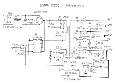
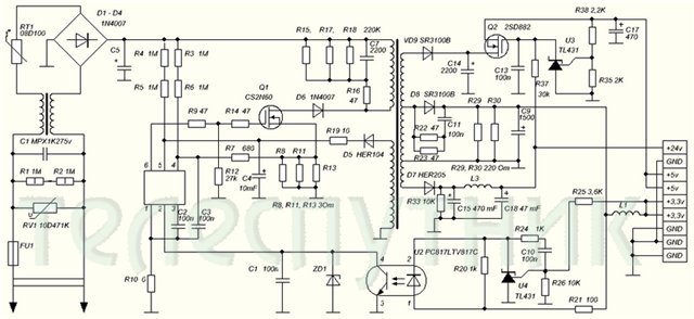
On Telesputnik posted a diagram of the power supply unit.
There are inaccuracies:
1. The lower terminal of the primary winding must be connected
to the junction point of the anode D6 and drain Q1
2. Positional designations C2 and C3 are incorrect. C3 must be connected to the 3rd pin
U1, C2 to the 4th pin of U1.
3. Nominal C3 = 68nF
4. In the diagram, there are two capacitors C1
5. Missing C12
6. The primary land is designated in the same way as the secondary one.
7. Missing C8
8.Q2 - MOSFET NTD14N03R
9.Rated C11 = 2200pF
10. Type D8 = SR560
11. Positional designations U3 and U4 are incorrect - they must be reversed.
12. Denomination C5 = 47µF
The receiver turns on, the LNB has 18 volts. There is no video signal, it gets very hot (the finger does not hold) stv 6419 .. because of it there can be no video? there is no other point? (in the sense that more video signal is not to be taken from?) the receiver switches channels ..
GS 8300N receiver there is no video and audio signal through scart to the TV, the channels are switched on the receiver panel.
the video signal from the STi5119ALC chip can be checked with an oscilloscope at the control point opposite the capacitor C117, then it comes to the resistor R87 and is transmitted to the capacitor C129 and then goes to the STV6419 microcircuit from it there is no output to R91, the culprit is not 12 volts on the board, respectively, there is no power + 12V on the 3rd leg STV6419, a 12 volt Zener diode D3 is faulty near the power connector
There was such an answer: if you use only composite video signal, most likely it can be simply thrown out (replaced with a jumper). And where to put the jumper? if that's the right advice ..
Defective VD3 (VD3 zener diode 12 V) on the motherboard next to the power connector.
Zener diode brand and parameters:
Power supply + 12V for 3rd leg STV6419.
Along the chain: XP5 connector 9th leg -> R81 (300 Om) + Zener diode VD3 (12V) = stabilizer + 12V -> L3 -> 3rd leg STV6419.
Zener diode analog:
VD3 STV6419 similar Zener diode (SMD) did not find. Put a 0.5 watt glass zener diode the size of a diode kd522 ... While the flight is normal.
If replacing the zener diode did not help:
After the thunderstorm, 6419 swelled. After the replacement, the image did not appear, but when checking the strapping, two resistors were cut off, R91, R95... I replaced it, and it worked.
One more problem:
And yet, instead of 13, 18 Volts, 24V was running on the LNB. Replacement required DA1 (LM317T)... And that's it, the flight is normal
The same situation with the GS-8304 receiver:
After 5 years of operation, the GS-8304 suddenly stopped broadcasting, although the indication is working properly.
Zener diode struck at short circuit. Zener diode brand MMZE5242B.
Satellite TV is evolving with every update and with every new device. Every satellite TV user from time to time encounters problems and errors in the robot of their receivers or other components. This can be due to various factors. For example, older models may fail due to long operating times. Despite their quality and reliability, devices can break down due to unsatisfactory weather conditions, electrical problems or improper use. Let's take a closer look at this.
Among the reasons for the breakdowns of the GS8306, GS8300, DRS-5001 models are the following:
- the receiver does not start;
- the timer flashes on the display of the set-top box at startup;
- on the display of the prefix only a non-blinking timer;
- on the display of the prefix the inscription "boot";
- on the display of the prefix error message ER31;
- an error on the TV display when switching on "Short circuit!" or "Check antenna cable".
In the case of the last error, you can carry out diagnostics yourself to clarify the cause of the malfunction. When the wire was disconnected, the error message disappeared, the problem is with the satellite converter or the antenna cable. Next, you need to check the wire in case of a short circuit. If it is not there, there is an error in the satellite converter. But, if the TV still signals an error, the problem is in the tuner.
These types of breakdowns include other representatives of the series of MPEG-2, MPEG-4 and Full HD set-top boxes. There is no need to prematurely go to the store for another device, because the purchase will definitely cost a lot. It is recommended to contact service center for qualified help, or repair the receiver with your own hands, if you have the necessary skills.
Diagnostics show that often the accessories of the set-top box fail:
- firmware - this can be detected if you see errors on the display;
- receiver power supply Tricolor - when the receiver does not turn on or the timer is flashing;
- motherboard - only timer is displayed or in case of error ER
However, satellite TV users may encounter picture, sound or signal problems. This also happens due to problems with the receiver. The following are attributed:
- breakdown of the satellite converter;
- the antenna cable is damaged;
- breakdown of the tuner unit;
- weak signal due to obscuring trees;
- unsatisfactory weather conditions.
The reasons also include channel broadcasting frequency change or even a whole package of channels or satellite malfunctions, to which the service center has nothing to do.
First of all, you do not need to start repairing Tricolor receivers yourself if you are not 100% sure what and how you are doing. If the warranty period is valid, it is best to entrust the repair of the Tricolor satellite receiver to a specialist. But, this is possible if there is a warranty card, purchase receipt, client's signature. The repair warranty may be voided if:
- operation of the receiver during power surges;
- damage to the seal or the integrity of the structure;
- errors when switching, connecting cables or incorrect programming;
- the receiver was not installed by an installer, and this led to a breakdown during operation;
- the client has violated the terms of use;
All this must be adhered to if the client wishes to repair his receiver in the future.
Repair of the Tricolor TV receiver is as follows:
- replacing the motherboard;
- changing the power supply;
- replacement of the module;
- flashing or reinstalling software.
If the motherboard breaks down, it is most often recommended to buy a new and more modern version of the set-top box, because repairing the motherboard will cost almost at the price of a new receiver.
For example, there are a number of errors typical for each type of device and options for correcting. The peculiarity of the repair of the GS8300 receivers of the Tricolor company depends on the alteration of the power supplies, because the devices are not highly resistant to voltage surges. Overheating was a typical problem for the GS 7300, causing the diode bridge or chip to break. Also, the power supplies for the Tricolor receivers sparked after prolonged operation, so they often had to be changed. The most optimal model, the GS8306, also had typical problems. For example, overheating during prolonged viewing of channels.
The main and most common malfunction of all receivers is a malfunction in the power supply and voltage conversion circuit. Also, the modulator often fails due to a short circuit in the coaxial cable from the LNB, although the latest models have good protection against short circuits in the cable, when triggered, the voltage supply to the converter simply stops until the short circuit is eliminated.
And so, our receiver does not show any signs of life, the indicators on the front panel display do not light up, and no twitching of the power plug from the outlet and turning on the toggle switch does not help us (at least that was the case with the device, an example of which is given in this article) ... The first thing we do is pull out the plug from the network and remove the top cover, we need to get to the electronic filling of the device. And here it is important to remember one thing, namely, about the warranty seal, which of course we will break if we remove the cover. Therefore, once again make sure that the warranty period has definitely expired, and under warranty no one will repair it for you. If the warranty is still valid, I advise you to take the receiver to a service center and entrust this matter to a specialist.
Receiver inside:
The electrolytic or oxide capacitor at the input often dries up and fails, which is also a malfunction, not everyone can find such a breakdown either, you need to have at least an initial level of a radio amateur. Usually, defective capacitors are swollen, yellowish, or have a small brown speck on the board at the base of the legs. Also, the serviceability of a capacitor can be determined by comparing its nominal and measured capacitance.
The receiver uses direct current, which is rectified from the AC mains using a diode bridge. Problems with the diode bridge also happen. It is very simple to check diodes, the main function of a semiconductor diode is to pass current in one direction, and not in the other. In my case, the transistor of the primary winding of the transformer turned out to be faulty, it is not difficult to find it, it usually has a radiator to remove heat. I determined the malfunction of the transistor by measuring the voltage at its emitter, it was absent there, the primary winding was not powered, respectively, everything else is de-energized. The transistor cost me 28.5 rubles. Replacing it with a soldering iron, I eliminated the malfunction and the receiver is back in working order. I must say such a breakdown is quite a rare occurrence, usually it all ends with a fuse.
A very common malfunction is a firmware crash. The firmware often crashes, this is usually evidenced by the complete hang of the receiver. In this case, "flashing" will help. I will say about one more reason for the malfunction, which may arise due to poor-quality installation. Water in the cable. If the outer insulation of the cable is broken, then water from atmospheric precipitation can get inside it, it easily, like a hose, gets into the receiver, sometimes flooding all of its insides. The condition of the cable must be monitored throughout the entire service life of the device.
Is registered: 06.04.
Posts: 19
Is registered: 03.08.
Posts: 313
Location: Ural
Is registered: 20.02.2009
Posts: 949
From: Moscow 37.7E 55.6N
Is registered: 06.04.
Posts: 19
The same tuner connected it to a smaller plate, everything shows, so the memory has not flown off. Signal strength scale is completely absent.
Is registered: 06.04.
Posts: 19
Is registered: 06.04.
Posts: 19
Is registered: 20.02.2009
Posts: 949
From: Moscow 37.7E 55.6N
Is registered: 06.04.
Posts: 19
Is registered: 26.03.
Posts: 2438
Location: Ural
Is registered: 06.04.
Posts: 19
Is registered: 09.08.2007
Posts: 943
Location: Samara region 52 * 51N 48 * 36E
Is registered: 06.04.
Posts: 19
Is registered: 16.08.2009
Posts: 76
Is registered: 31.08.2006
Posts: 229
Location: Russia, Abakan, 53 ° 46'N 91 ° 26'E
Is registered: 20.02.2009
Posts: 949
From: Moscow 37.7E 55.6N
Is registered: 08.08.2006
Posts: 164
Location: Mensk
Is registered: 31.12.2006
Posts: 169
Is registered: 08.08.2006
Posts: 164
Location: Mensk
Is registered: 31.08.2006
Posts: 229
Location: Russia, Abakan, 53 ° 46'N 91 ° 26'E
Well, if these are crows, then this is such a "protection"
at least it will show "birds" or schmuck.
_________________
1.5m GS (40ku), 1.5m GS (90C + 96.5C + 80C), 1.2m GS (96.5ku + 90ku + 85.2ku), 0.9m GS (75ku); TT-1401x2, Tevii S460x2, S464, S650, Euston 525 +, Telestar SSC1
HTPC in the hall
NTSC in the nursery
Is registered: 12.07.2006
Posts: 362
Location: Novosibirsk
The article discusses the issues of assembling, setting up and adjusting the Tricolor antenna with your own hands.
Having bought the Tricolor antenna, everyone can carry out their own tuning, subject to certain rules.
Tricolor satellite TV installation kit.
- Drill (puncher);
- Screwdriver;
- Spanners for 8, 10, 13;
- Open-end wrench 10;
- Pliers;
- Compass;
- Knife;
- Insulating tape;
- Silicone based heat shrink tubing or sealant;
- Screeds;
- Socket screws 13, length 6 - 8 cm;
- Metal washers d = 30-50 mm.
The minimum set of tools.
To secure the base, you need to select fasteners. It should be fixed on a wooden surface with the help of plumbing "wood grouses". In other situations, anchor bolts 10x100 are suitable.
The cable used to connect the antenna to the TV must have a thick copper core and double braid. Cable length no more than 100 m.If it is required to lay more than this length, then signal amplifiers are additionally located.
Since the dish receives a signal from the satellite, the main criteria for choosing a location are:
- There are no foreign objects on the signal path (trees, pillars, walls, glass, building) at a distance of 100 m in length and 40 m in height.
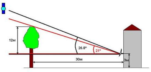
- Fixation takes place at a high point (roof, wall, balcony side). When placed inside the balcony, interference will appear.
- The dish should face south, because the satellite "hangs" over the equator. As a result, the quality of transmission of digital messages is improved.
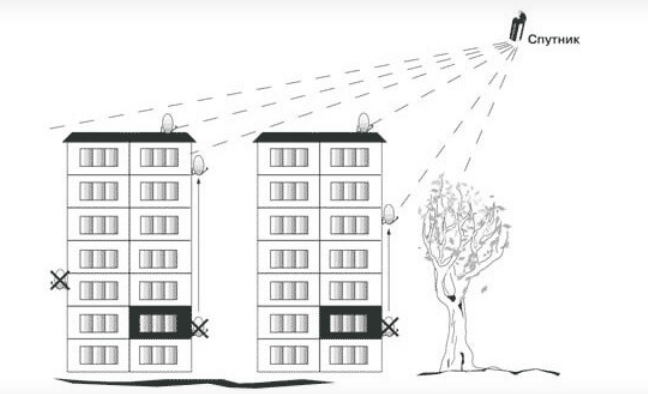
- To exclude the ingress of snow slopes, water drains, falling of eaves onto the equipment.
- Placing it close to the TV will make it easier to set up the broadcast.
Adherence to the criteria will ensure that there are no mistakes in independent work.
The equipment comes with assembly instructions, following which you can do everything quickly. The structure for receiving a signal is formed by the elements:
-
Bracket - holds the mirror, so it must be mounted on a wall, mast or roof.
- After choosing the installation location, mark up in order to mount the bracket.
- Make holes for fasteners with a drill or punch.
- Secure the bracket.
Roof bracket mounting option.
Assembly work completed.
Adjustment should be carried out in good weather (no snowfall, rain, dense clouds). The stage involves the creation of a certain position of the equipment for the clarity of the broadcast. They depend on the elevation and azimuth angle. To calculate the elevation angle, draw a horizontal line from the installed dish in the direction of the satellite and measure the angle formed by this line and the signal receiving line (the vertical angle formed when the mirror is turned up and down).
There is a table showing the elevation and azimuth for different cities. If the plate is not installed in a city, then you need to focus on a nearby city.
Azimuth for different cities.
The azimuth angle is set by the compass. You can use a protractor and a plumb line to determine the elevation angle. The plumb line is located at the zero point of the protractor and serves as a conditional horizon line. The required angle is shown on the protractor scale.
Different manufacturers design the antenna at different angles. Supral products are characterized by an accurate vertical position of the antenna at an angle of 26.5 °. When placing equipment with such an angle in Moscow or Kaliningrad, it is not necessary to change the elevation angle. For other cities, it will be necessary to tilt the structure forward or backward so that the angle corresponds to the required value.
The TV connector is connected to the converter in accordance with the diagram:
- Strip the top insulated layer of the cable to a length of 1.5 cm.
- Expand the braided shield along the wire.
- Unscrew the foil over the sheathing.
- Remove the insulating layer of the conductor 1 cm long.
- Install the cable in the F-connector.
- Leave protruding center conductor 2 mm long (cut off excess).
- Seal the F-connector along the entire length. This is done with a heat-shrinkable tube or 2 layers of electrical tape covered with a silicone-based sealant.
- Fix the cable in the arc space of the converter by applying a layer of electrical tape or tie.
- Connect the other end of the wire to the receiving equipment.
With regard to the antenna wire used, there are two ways to install the receiver to the TV:
- High Frequency Antenna Cable (HF) - Plugs into the antenna socket on the TV and into the RF Out port of the receiver. After switching on, the combination "BOOT" and the channel number appear on the TV screen. When the channel search function is turned on, the notification “No signal” is displayed, which implies normal operation of the receiver.
- Low-frequency cable with connector (LF) - similar to HF.When connected, “BOOT” appears on the TV screen. Then it is necessary to press the button "A / B" on the control surface of the receiver. As a result, the notification "No signal" should light up. The appearance of other information indicates the incorrect assembly of the equipment.
After the steps taken, you can start setting up the channels.
Tuning must be done by changing the position of the antenna and monitoring the signal level on the television screen. First open the menu "Antenna installation":
- Find the "Menu" button on the receiver's remote control and press it;
- Stop at the sub-item "Settings";
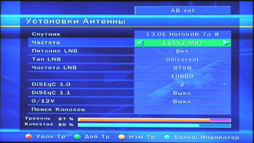
- Enter the combination "0000" in the password field;
- Click on "System Preferences";
- Select the item "Antenna installation".
After the two scales "Signal" and "Quality" are displayed, the equipment location should be adjusted:
- Initially, the mirror looks to the south side (it is determined by the compass or by the time the sun is in the south in a certain region);
- Install the antenna vertically if there are no obstacles;
Antenna presetting.
Watching TV, analyzing the content of the scales:
- In the absence of filling, continue rotating the plate;
- The filling of one indicator indicates the presence of an obstacle or fixation of false data (another satellite), therefore, the rotation should be resumed;
- Filled scales and the absence of a picture confirms the finding of a false signal source;
- If the data will come from the desired satellite, a picture will appear on the information channel, and the scales will be filled (the information channel is selected by pressing the “OK” button on the receiver's remote control).
Presetting ends with fine tuning when, when changing the position of the cymbal left-right and up-down, both scales are filled at 80%. Such values will help to transmit an accurate signal in bad weather (heavy rain, snowfall, cloudy).
After fine-tuning the telecast, you should firmly fix the equipment on the street and exit the setup menu by pressing "Exit" twice on the remote control.
Receiving a television picture occurs after the registration of the equipment. Registration is carried out in one of the following ways:
- On the Tricolor website;
- At the sales office or authorized center (usually, after the purchase at specialized points of sale, the receiver is registered);
- Through the technical support department, when you have a subscription agreement.
The identification number is a 10-12 digit sequence. The number can be found on the package sticker or on the receiver body sticker. Some packages and cases do not have an inscription, so you need to go to the receiver menu. By clicking on the "Status" submenu, the user will see the ID.
To conclude an agreement, it is required to provide the user's personal data (full name, passport, date of birth, place of installation, contact information).
Registration actions end with the confirmation of the equipment by telephone conversation with the Tricolor service. You should indicate the purpose of the appeal, name, identification number.
"Do I need a special device to tune satellite dishes?"
A self-tuning tool is not required, but it can make it easier to find the satellite signal.
| Video (click to play). |
"What parameters should I use to tune the satellite dish?"

