In detail: do-it-yourself repair of the ZIL 130 gearbox from a real master for the site my.housecope.com.
SPARE PARTS AND ASSEMBLY PARTS
SPECIAL EQUIPMENT BASED ON URAL, MAZ, KAMAZ ____________________
Dismantling the ZIL-130 checkpoint into nodes
To disassemble the ZIL-130 gearbox into units, a rotary stand is used, on which five gearboxes can be installed simultaneously.
Gearbox 1 is fixed on the stand with clamps 2 and 5. Handle 4 allows you to turn the gearbox to a position convenient for disassembly.
Unscrewing bolts 15 and 21 (Fig. 30) with spring washers 6, remove the gearbox shift mechanism and gasket 23.
To remove the right and left side covers 7 (Fig. 31) with gaskets 3, unscrew six bolts 5 with spring washers 6 with an L-shaped wrench.
Rice. 30. Details of the gear change mechanism ZIL-130
1 — gear shift lever handle; 2 - lever cover; 3 - lever stopper; 4 - gear shift lever; 5, 15, 21 — bolts; 6 — spring washers; 7 - gear lever housing; 8 — axis of the intermediate lever; 9 and 23 - gaskets; 10 - axle nut; 11 — reverse gear switch fuse; 12 - fuse spring; 13 - fuse washer; 14 - cotter pin; 16 - breather; 17 - intermediate lever for switching the first gear and reverse; 18 - support of the lever; 19 - lever spring; 20 - the positioning sleeve of the lever housing; 22 — transmission cover; 24 and 39 - plugs; 25 - fork
shifting the second and third gears; 26 - rod of switching of the second and third gears; 27 - shift fork of the fourth and fifth gears, 28 - shift rod of the fourth and fifth gears; 29 and 33 - cotter pin wire; 30 - rod for switching the first gear and reverse; 31 — head of the first gear and reverse gear shift rod; 32 - locking bolt; 34 - fork for switching the first gear and reverse; 35 - balls of the lock of the rods;
36 — rod lock pin; 37 - locking ball; 38 - retainer spring
| Video (click to play). |
To dismantle the drive shaft 11, unscrew the bolts 17 securing the bearing cover 15 to the gearbox, remove the cover and cover gasket 8.
With the help of a mandrel made of soft metal and a hammer, the drive shaft 11 with the bearing 12 is shifted forward so that they come out of the housing 1 of the gearbox, and the roller bearings 10 are removed from the drive shaft gear, having previously removed the circlip 9.
The driven shaft 54 of the ZIL-130 gearbox with the bearing is displaced back from the crankcase 1 using a soft metal mandrel and a hammer so that the ball bearing comes out of the slot in the gearbox crankcase, and the synchronizer 42 of the fourth and fifth gears is removed.
The ball bearing 59 of the driven shaft is removed with a puller, and the drive gears 61 and 67 of the speedometer drive are removed by hand. The circlip 60 is removed from the ball bearing 59 using two screwdrivers or a puller.
Raising the front end of the gearbox housing 1, take out the driven shaft 54, complete with gears and gear 53 of the first gear. To remove the block of reverse gears, unscrew the locking bolt 5 of the reverse axis, remove the spring washer and the stop 22 of the axis.
The axle 21 of the reverse gear block of the ZIL-130 gearbox is removed with a puller and the gear block 18 with roller bearings 19 is removed from the crankcase 1. Roller bearings 19 and the spacer sleeve 20 are removed from the gear block.
Having unscrewed four bolts 17 with spring washers 6, remove the cover 24 of the rear bearing of the intermediate shaft with a gasket 26. Having previously unbent the rolled part, unscrew the nut 25 of the rear bearing of the intermediate shaft.
Using a soft metal mandrel and a hammer, the intermediate shaft 29 is pressed back so that the rear ball bearing 28 and the front journal of the shaft come out of their seats.
With the help of a tool, the circlip 27 is removed from the rear bearing 28, and the rear bearing 28 is removed with a puller.
Having removed the intermediate shaft 29 assembled with gears from the crankcase 1, using a mandrel made of soft metal and a hammer, knock out the plug 40 and the front roller bearing 38, and remove the retaining ring 37 from the seat of the front bearing using a tool.
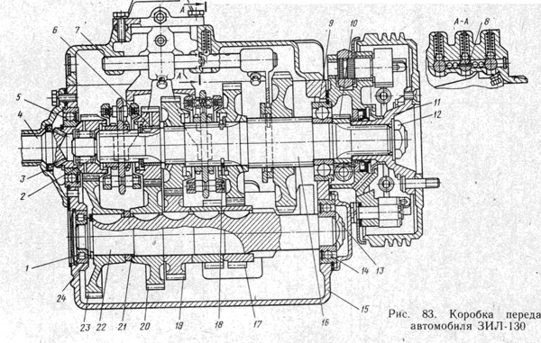
Fig. 31. Details of the ZIL-130 checkpoint
For disassembly, the drive shaft 11 (see Fig. 31) is installed in a stand and secured with a screw. Bending back the rolled edge, unscrew the nut 14 (see Fig. 31). Then, on a press, using a mandrel, the bearing 12 of the drive shaft is pressed.
For disassembly, the driven shaft of the ZIL-130 gearbox is installed in a stand similar in design to the stand for the drive shaft. Using a screwdriver and pliers, remove the retaining ring 43 and thrust washer 44, and then the fourth gear 45 and its sleeve 46.
Then remove the gear 48 and the thrust washer 47 of the third gear, the synchronizer 49 of the second and third gears. Having previously removed the retaining ring 50 using pliers and the thrust washer 51, remove the gear 52 of the second gear.
The intermediate shaft 29 is installed on a support and the retaining ring 37 is removed with pliers. Then the intermediate shaft is installed on the press table and the gears 36, 34, 33, 32 and 31 are pressed using a mandrel, the spacer sleeve 35 is removed and the keys 30 are knocked out with a chisel and hammer.
Having unscrewed four bolts 5 (see Fig. 30) with spring washers 6, remove the crankcase 7 of the ZIL-130 gearbox shift lever. Having secured the crankcase 7 in a bench vice so that the handle 1 is directed downward, unscrew the nut 10 securing the intermediate lever axis.
While holding the axle head, the spring washer and the axle 8 with the intermediate lever 17 for switching the first gear and reverse gear are removed from the axle.
Then the axle 8 is removed from the hole of the lever 17, the fuse is unpinned, the thrust washer 13 of the fuse is removed and the spring 12 and the fuse 11 for reverse gear are removed from the socket.
After that, the spring 19 is freely removed from the crankcase, the lever support 18 is removed, the gear shift lever 4 is removed as an assembly and the lever stopper 3. To remove the cover 2, loosen the lever nut 4 and unscrew the handle 1.
The gear shift mechanism of the ZIL-130 gearbox is disassembled into a device that allows you to quickly and reliably fix the cover using an eccentric clamp and a pressure lever in a position convenient for disassembly.
Disassembly of the gear shifting mechanism begins with unpinning the locking bolts 32 (see Fig. 30) fastening the forks and safety heads on the rods.
Having unscrewed the locking bolts for fastening the forks and the rod heads, the shaft 28 of the shift of the fourth and fifth gears is moved along the axis with a wrench and the plug 24 is pressed out of the socket.
Moving the rod 28, remove the fork 27 for shifting the fourth and fifth gears and, holding the locking balls 35 of the rod lock with your left hand, remove the rod with your right hand. Similarly, remove the second and third gear shift rod, and then the first gear and reverse gear shift rod.
Disassembly of the synchronizer of the second and third gears of the ZIL-130 gearbox begins with drilling the locking fingers. To do this, the synchronizer is installed on a support and on a drilling machine with a 12 mm drill, three fingers are drilled from both sides to a depth of 2 mm.
To remove the ring from the locking fingers, the carriage is installed on a support and the ring is pressed in, while removing the clips, balls and springs. The locking fingers of the rings are also pressed out on the support, placing the fixture on the press table.
Similarly, the ring supports are pressed out and the second synchronizer ring is disassembled. The order of disassembly of the synchronizer of the fourth and fifth gears is similar to the above-described technological process.
Assembling the ZIL-130 gearbox
To assemble the ZIL-130 gearbox, both single-post and multi-post stands are used. A replaceable head is attached to the gearbox housing.
With a hoist, a crankcase with a replaceable head is fed to the stand and fixed on the carriage. Parts and assemblies used to assemble the gearbox are located on the frame rack.
Plug 23 is screwed into the oil filler hole (see Fig. 31), and plug 4 with a magnet is screwed into the drain hole. Retaining ring 39 is inserted into the housing of the crankcase 1 using pliers.A roller bearing 38 is put on the front end of the intermediate shaft 29.
Then the intermediate shaft 29 assembled with gears is inserted into the crankcase 1, sequentially directing the rear end of the shaft into the seat of the ball bearing, and then the front end of the shaft 29 with the roller bearing 38 is installed in the outer ring.
Putting the retaining ring 27 on the ball bearing using pliers, it is pressed onto the rear end of the intermediate shaft of the ZIL-130 gearbox.
Then the rear end of the intermediate shaft 29, assembled with the bearing, is installed by means of a mandrel into the housing of the crankcase 1. The nut 25 is screwed onto the threaded end of the shaft 29 and tightened with a torque wrench with a torque of at least 25 kgm.
Then the nut 25 is nailed by pressing its edge into the groove of the shaft 29. Having previously assembled the bolts 17 with the spring washers 6 with the gasket 26, the cover 24 is installed on the socket of the rear ball bearing 28, screwing the bolts 17 by hand onto two or three threads.
Finally, the bolts are tightened with a torque wrench (tightening torque 2.0-3.5 kgm). When properly assembled and installed in the crankcase 1, the intermediate shaft 29 should easily rotate by hand in the bearings.
The assembly of the reverse gear block of the ZIL-130 gearbox begins with the installation of roller bearings 19 into the hole of the gear block 18, between which the spacer sleeve 20 is located.
The axle 21 of the gear block is pressed in with a copper hammer to the stop of the end of the groove of the axle 21 with the plane of the crankcase. Then the stopper 22 is fixed on the crankcase so that it fits into the groove of the axle 21. The bolt 5 of the stopper with a spring washer 6 is tightened with a torque wrench (tightening torque 1.5-2 kgm).
Having previously assembled the right and left hatch covers 7 with gasket 3, bolts 5, spring washers 6, they are installed to the crankcase hatches 1, and the bolts are tightened (tightening torque 1.5-2.0 kgm). The intermediate shaft plug 40 is installed in the crankcase hole 1 and distributed in the socket using a mandrel.
An o-ring 41 is installed in the groove of the seat of the front roller bearing 38. For assembly, the driven shaft 54 is assembled into the gearbox housing 1. Retaining ring 60 is installed on the rear ball bearing 59 with special pliers.
The ball bearing 59 is then slid onto shaft 54 with the circlip facing outward. Bearing 59 is pressed onto the shaft and into the hole of the ZIL-130 gearbox housing using a mandrel and a hammer.
On the end of the shaft 54 protruding from the crankcase 1, the drive gear 67 of the speedometer is installed and
with a mandrel, press it in until it stops in the bearing.
For assembly, the drive shaft 11 assembled with the bearing 12 is installed in the crankcase seat. Having removed the technological mandrel, the driven shaft 54 is installed so that its end fits into the seat of the drive shaft 11. Using the mandrel, the bearing 12 is pressed into the crankcase together with the drive shaft 11.
Then the cover 15 with the gasket 8 is installed and screwed to the crankcase 1 with bolts 17 with spring washers 6. Before installing the gearshift mechanism on the box, all gears and couplings on the driven shaft 54 are set to the neutral position.
Then put a gasket 23 (see Fig. 30) and a cover with a gearshift mechanism, directing the ends of the gearshift forks into the annular grooves of the gears and the carriage clutch. After that, the gearshift mechanism is attached to the crankcase with bolts and spring washers.
With proper assembly, all the shafts and gears of the ZIL-130 gearbox should be easily rotated by hand force applied to the drive shaft shank at any engaged or neutral position of the gears, without the slightest signs of jamming in bearings, in gear engagement and other connections.
To disassemble the gearbox into units, a rotary stand is used (fig. PO), on which five gearboxes can be installed simultaneously. Gearbox 1 is fixed on the stand with clamps 2 and 5.Handle 4 allows you to turn the gearbox to a position convenient for disassembly.
Unscrewing bolts 15 and 21 (Fig. 111) with spring washers 6, remove the gearbox shift mechanism and gasket 23.
To remove the right and left side covers 7 (Fig. 112) with gaskets 3, unscrew six bolts 5 with spring washers 6 with an L-shaped wrench.
To dismantle the drive shaft 11, unscrew the bolts 17 securing the bearing cover 15 to the gearbox, remove the cover and cover gasket 8. With the help of a mandrel made of soft metal and a hammer, the drive shaft 11 with the bearing 12 is shifted forward so that they come out of the housing 1 of the gearbox, and the roller
bearings 10 from the drive shaft gear, after removing the circlip 9.
The driven shaft 54 of the gearbox with the bearing is displaced back from the crankcase 1 using a soft metal mandrel and a hammer so that the ball bearing comes out of the seat in the gearbox housing, and the synchronizer 42 of the fourth and fifth gears is removed. The ball bearing 59 of the driven shaft is removed with a puller, and the drive gears 61 and 67 of the speedometer drive are removed by hand. Retaining ring 60 is removed from the ball bearing 59 using two screwdrivers or a puller. Lifting the front end of the gearbox housing 1, remove the driven shaft 54 with gears and gear 53 of the first gear.
To remove the block of reverse gears, unscrew the locking bolt 5 of the reverse axis, remove the spring washer and the stop 22 of the axis. With a puller, remove the axle 21 of the reverse gear block and remove the gear block 18 with roller bearings 19 from the crankcase 1. Roller bearings 19 and the spacer sleeve 20 are removed from the gear block.
Having unscrewed four bolts 17 with spring washers 6, remove the cover 24 of the rear bearing of the intermediate shaft with a gasket 26. Having previously unbent the rolled part, unscrew the nut 25 of the rear bearing of the intermediate shaft. Using a mandrel made of
soft metal and a hammer press the intermediate shaft 29 back so that the rear ball bearing 28 and the front journal of the shaft come out
Rice. 111. Details of the gear shift mechanism:
1 — gear shift lever handle; 2 - lever cover; 3 - lever stopper; 4 - gear shift lever; 5, 15 c 21 — bolts; 6 — spring washers; 7 - gear lever housing; 8 — axis of the intermediate lever; 9 and 23 - gaskets; 10 - axle nut; 11 — reverse gear switch fuse; 12 - fuse spring; 13 - fuse washer; 14 - cotter pin; 16 - breather; 17 - intermediate lever for switching the first gear and reverse; 18 - support of the lever; 19 - lever spring; 20 - the positioning sleeve of the lever housing; 22 — transmission cover; 24 and 39 - plugs; 25 - fork for shifting the second and third gears; 26 - rod of switching of the second and third gears; 27 - shift fork of the fourth and fifth gears; 28 - shift rod of the fourth and fifth gears; 29 and 33 - cotter pin wire; 30 - rod for switching the first gear and reverse; 31 — head of the first gear and reverse gear shift rod; 32 - locking bolt; 34 - fork for switching the first gear and reverse; 35 - balls of the lock of the rods; 36 — rod lock pin; 37 - locking ball; 38 - retainer spring
from their nests. With the help of a tool, the circlip 27 is removed from the rear bearing 28, and the rear bearing 28 is removed with a puller. After removing the intermediate shaft 29 from the crankcase 1, complete with gears, using a mandrel made of soft metal and a hammer, knock out the plug 40 and the front roller bearing 38, from the seat of the front bearing, remove the circlip 37 using a tool.
Removal and disassembly of the gear lever housing. Unscrew the four bolts securing the lever housing, remove the housing with the lever assembly and the crankcase gasket.
Fasten the lever housing in a vice with the lever pointing down. Unscrew nut 3 (Fig.3-4) fastening the intermediate lever axle, while holding the axle head, remove the spring washer and the axle 4 with the intermediate lever. Then remove the axle from the hole in the lever and the fuse. Remove the spring 5 from the crankcase, remove the support 6 of the lever, remove the lever 10 as an assembly and the lock 7 of the lever. To remove the protective cover 9, loosen the nut 11 and unscrew the handle 12.
Unscrew the bolts securing the box cover, remove the cover assembly with the mechanism and the gear lever, remove the cover gasket. If the gasket is stuck, carefully peel it off with a screwdriver or other tool.
The gearbox shift mechanism is disassembled in a device (Fig. 3-5), in which the cover is fixed in a position convenient for disassembly. In the absence of a device, the cover can be disassembled by fixing the cover in a vice.
Disassembly of the gearshift mechanism must be carried out in the following order. Undo the locking bolts for fastening the forks and safety heads on the rods 9, 10 and 11 (Fig. 3-6), unscrew the locking screws securing the forks and the bolts for securing the rod heads. Using the knob, move one gear shift rod and press the plug out of the socket. Moving the stem, remove the plug and, holding the locking balls with your hand, remove the stem with the other hand. Remove the other two gear shift rods in the same way.
Disconnect the return spring from the clutch release bearing, remove the clutch with bearing assembly. Remove the four bolts securing the input shaft front bearing cover and remove the cover with the gasket.
To remove the input shaft from the crankcase, it is necessary to press out the ball bearing using a 40P-5019 puller (Fig. 3-7) and remove the shaft and bearing assembly.
Remove the locking rings 2 (Fig. 3-8) and press the bearing together using a tool.
Remove the speedometer drive pinion from the end of the output shaft. Press out the output shaft bearing together with the shaft from the housing of the box using a mandrel and a hammer. Press the secondary shaft bearing using the tool (Fig. 3-9), remove the secondary shaft assembly with gears and synchronizers from the box crankcase (Fig. 3-10, a).
Remove the synchronizer 1 (Fig. 3-11) of the fourth and fifth gears, gear 12 of the first gear from the shaft. Use two screwdrivers (see Fig. 3-10, b) to remove the lock ring 2 (see Fig. 3-11) of the fourth gear fastening. Remove thrust washer 3 together with gear 4 of fourth gear and steel sleeve 5 with a stopper, thrust washer 6 and gear 7 of third gear, synchronizer 8 of second and third gear. Use two screwdrivers to remove the second gear retaining ring. Remove the thrust washer and the second gear. The synchronizer should not be disassembled unnecessarily.
Unscrew the bolt securing the block of the reverse gear axle, remove the stopper, remove the block axle, the gear block, two roller bearings and the spacer sleeve from the crankcase.
Unscrew the four bolts securing the intermediate shaft rear bearing cover, remove the cover with the gasket, bend the thin edge of the nut, lock the intermediate shaft gear with a knob and unscrew the rear bearing retaining nut.
Press out the rear bearing together with the intermediate shaft from the housing of the crankcase, slide the shaft with gears axially towards the bearing. Press the rear bearing of the intermediate shaft using a puller.The method of pressing this bearing from the shaft is the same as pressing the bearing from the secondary shaft, shown in fig. 3-9.
Remove the intermediate shaft with gears from the crankcase by hand (Fig. 3-12).
Remove front intermediate shaft bearing from housing seat. If necessary, knock out the plug that covers the front bearing using a mandrel and remove the circlip.
To disassemble the intermediate shaft, remove the lock ring 1 (Fig. 3-13), press all the gears off the shaft and remove the keys from the slots. The gears can be pressed using the tool (Fig.3-14) or with press pads.
The last two gears 6 (see Fig. 3-13) reverse gear and 7 second gear must be pressed together.
To remove the axis 55 (see Fig. 3-1) of the reverse gear block, use a puller model I.803.20.00 (Fig. 3-15).
When removing the gearbox, it is necessary to unscrew the bolts securing the cab floor cover, remove it and unscrew the propeller shaft mounting flange. Unscrew the bolts securing the CCGT to the bracket, disconnect the pusher from the clutch fork lever and, without disconnecting the pipelines, fix the CCGT on the car so as not to damage the pipelines ... Remove crankcase with gear lever. Disconnect the intermediate support bracket from the frame cross member and lower the propeller shaft, disconnect the speedometer shaft.
Rice. 5-2. Removing the gearbox from the vehicle using a trolley jack
Rice. 5-3. Suspension for transporting gearbox
Rice. 5-4. Gearbox assembly and disassembly tool
Unscrew the nuts of the studs securing the gearbox to the clutch housing using a spanner wrench.
Disconnect the gearbox from the clutch housing and remove it using a trolley jack with a special puller 32P-1270 (Fig. 5-2).
Having removed the gearbox from the car, it is necessary to replace the crankcase with the gearbox control lever.
Before disassembling, it is necessary to drain the oil, unscrew the plug from the drain hole, then clean and rinse the gearbox from the outside.
Hook the gearbox using the suspension (Fig. 5-3), lift it with a hoist and install it on the device (Fig. 5-4) for disassembling and assembling the gearboxes.
Installation of the gearbox on the bus is carried out in the reverse order of its removal.
To remove and disassemble the crankcase of the gear lever tip, unscrew the first gear and reverse gear 62 Unscrew the four crankcase mounting bolts, remove the crankcase with the lever assembly and the crankcase gasket. Unscrew the nut from the tip, remove the lever and remove the key.
Secure the lever tip housing in a vise with the tip pointing down. Unscrew the nut 3 (Fig. 5-5) securing the intermediate lever axle, while holding the axle head, remove the spring washer and the axle 4 with the intermediate lever. Then remove the axle from the hole in the lever and the fuse. Remove the spring 5 from the crankcase, remove the support 6 of the lever, remove the lever 10 as an assembly and the lock 7 of the lever.
Unscrew the bolts securing the box cover, remove the cover assembly with the gearshift mechanism, remove the cover gasket. If the gasket is stuck, carefully peel it off with a screwdriver or other tool.
The gearbox shift mechanism is disassembled in a device (Fig. 5-6), in which the cover is fixed in a position convenient for disassembly. In the absence of a device, the cover can be disassembled by fixing the cover in a vice.
Disassembly of the gearshift mechanism must be carried out in the following order.
Undo the locking bolts for fastening the forks and safety heads on the rods 9, 10, and 11 (Fig. 5-7), unscrew the locking screws securing the forks and the bolts for securing the rod heads.
Using the knob, move one gear shift rod and press the plug out of the seat.
Rice. 5-5. Crankcase assembly of the tip of the gear shift lever: 1 - intermediate lever cracker: 2 - intermediate lever for engaging the first gear and reverse gear; 3 - axle nut; 4 - the axis of the lever; 5- lever spring; 6 - support of the lever; 7 - lever lock: 8 - lever housing: 9 - protective cover; 10 - tip of the gear lever
Moving the stem, remove the plug and, holding the locking balls with your hand, remove the stem with the other hand. Remove the other two gear shift rods in the same way.
Disconnect the return spring from the clutch release bearing, remove the clutch with bearing assembly. Remove the four bolts securing the input shaft front bearing cover and remove the cover with the gasket.
To remove the input shaft from the crankcase seat, it is necessary to press out the ball bearing using a 40P-5019 puller (Fig.5-8) and remove the shaft and bearing assembly. (Usually the input shaft can be pressed easily without a puller, using two screwdrivers)
Remove the locking rings 2 (Fig. 5-9) and press the bearing together using a tool.
Removal and disassembly of the output shaft. Having locked the gear wheel of the first gear with a wrench, unscrew the nut of the output shaft flange, press the flange. Unscrew the bolts securing the output shaft cover and remove the cover with the gasket.
Remove the speedometer drive pinion from the end of the output shaft. Press out the output shaft bearing together with the shaft from the housing of the box using a mandrel and a hammer. Press the secondary shaft bearing using the tool (Fig. 5-10), remove the secondary shaft assembly with gears and synchronizers from the box crankcase (Fig. 5-11, a). Remove synchronizer 1 for fourth and fifth gears, gear 12 for first gear from the shaft. Remove with two screwdrivers (lock ring 2 securing the fourth gear gear. Remove thrust washer 3 together with gear 4 of fourth gear and steel sleeve 5 with a stopper, thrust washer 6 and gear 7 of third gear, synchronizer 8 for second and third gears. two screwdrivers lock ring securing the gear wheel of the second gear Remove the thrust washer and the gear wheel of the second gear Synchronizers should not be disassembled unnecessarily.
Unscrew the bolt securing the block of the reverse gear axle, remove the stopper, remove the axle of the block from the crankcase. To press out the axis 55 of the reverse gear block, a puller model I.803.20.00 is used (Fig. 5-13).
Unscrew the four bolts securing the intermediate shaft rear bearing cover, remove the cover with the gasket, bend the thin edge of the nut, lock the intermediate shaft gear with a knob and unscrew the rear bearing retaining nut. Press out the rear bearing together with the intermediate shaft from the housing of the crankcase, slide the shaft with gears axially towards the bearing. Press the rear intermediate shaft bearing with a puller. The method of pressing this bearing off the shaft is the same as pressing the bearing off the output shaft (Figure 5-10).
Remove the intermediate shaft with gears from the crankcase by hand (Fig. 5-14). Remove outer race of intermediate shaft bearing from housing in housing. If necessary, knock out the plug that covers the front bearing using a mandrel and remove the circlip.
To disassemble the intermediate shaft, press the inner ring of the bearing with the rollers, remove the lock ring 1 (Fig. 5-15), press all the gears off the shaft and remove the keys from the slots. The gears can be pressed together using a tool (Fig. 5-16) or using shims on the press. The last two gears 6 reverse and 7 second gear must be pressed together.
Rice. 6-2. 1 - synchronizer of the fourth and fifth gears; 2 and 9 - locking rings: 3, 10 - thrust washers; 4 - gear wheel of the fourth gear: 5 - bushing of the gear wheel. Of the fourth gear: 7 - gear wheel of the third gear: 8 - synchronizer of the second and third gears: 11 - a gear wheel of the second transfer; 12 - a gear wheel of the first gear: 13 - a secondary shaft, a block of gears, two roller bearings and a spacer sleeve
Rice. 5-15. Transmission intermediate shaft, assy1 - key ring; 2 - constant mesh gear; 3 - spacer sleeve: 4 - gear wheel of the fourth gear: 5 - gear wheel of the third gear; 6 - gear wheel of the rear axle: 7 - gear wheel of the second transfer: 8 - key; 9 - toothed rim of the first gear; 10 - shaft
Rice. 5-73. Puller model I803.20.00 of the axle of the reverse gear block
The sequence of stages of assembly of the drive shaft 11 of the gearbox (Fig. 1):
- First, the ball bearing 12 is assembled (this operation is called subassembly), for which the circlip 13 is installed in the groove of the part.
- The bearing is then put into place on the drive shaft. The bearing groove must face outward.
- The bearing is pressed on after placing the drive shaft on the press table, where a special device is provided.For this, a mandrel is used, with which the part is driven to the end on the shaft journal.
- Using a torque wrench, tighten the nuts 14 with a force of 20 kgm.
- To prevent accidental loosening, screw the collar of the part into the groove of the drive shaft.
- After installing the unit on the press table in a special device with grease, the internal gear seat is lubricated.
- Rollers 10 of the bearing are put in place.
Important! The last of the rollers must be loosely inserted; interference must be avoided. After completing this step, it is checked how easily the installed rollers rotate. Rotation should be free, but not falling out of the seat.
- Before installing the rollers, they are checked for belonging to the same size group. Permissible deviations from the established dimensions for each of the three groups:
- 8.0 - (0.003-0.008) mm.
- 8.0 - (0.005-0.010) mm.
- 8.0 - (0.008-0.013) mm.
Interesting: The installation of a roller bearing assembled into a cage began in 1967, when it was decided to switch to this method instead of installing separate rollers. This is due to the need to extend the life of the front bearing, on the one hand, and the desire to simplify the process of assembling / disassembling the gearbox.
- The circlip 9 is put into place after the rollers 10 are installed in the groove.
- Before the start of the operation to assemble the synchronizer of the 2nd and 3rd gears, three supports of the fixing device are placed in the device. The milled part of the surface of the supports (flat) must face outward.
- After installing the supports, which serve as locking pins, you need to align the holes. Then the rings are pressed onto the outer sides.
- The retainers are assembled (there are three of them, you need to collect balls and springs), which are placed in a seat in the carriage.
- The second ring is assembled in the same way, which is then hammered onto the blocking fingers.
Important! Care must be taken to ensure that the outer edges of the ring are in good contact with the end surfaces of the locking pins.
- Crimping the fingers with a ball on both sides is carried out after installing the carriage in the device with a force of 4600 kg.
- After assembling the synchronizer, it is necessary to check the force required to bring the carriage 2 out of the central position using a special device (Fig. 2).
Rice. 2. Device for checking the synchronizer for closing force
Synchronizer check consists in creating a load of a certain magnitude in order to turn on the synchronizer. The load confirming the suitability of the synchronizer is 20 kg. When checking, the carriage must be in neutral. The load is made with the handle 4 and should be smooth. To check, the synchronizer must be installed on the centering tapered bushing 1.
The assembly of the intermediate shaft 29 (Fig. 1) begins with pressing the gears:
- The shaft splines are lubricated.
- Then, a key 30 and a gear 31 of the second gear are installed in the groove.
- Fixation of the shaft in the bracket 6 is carried out on the prism of the stand 5 (Fig. 3). The force required for fixing is provided by the rod of the brake chamber 7. The brake chamber is controlled by the handle 4 of the pneumatic crane.
Rice. 3. Stand for pressing gears onto gearbox shafts
The task is to press the gear onto the shaft to the end. The force is transmitted from the pneumatic cylinder 2 through the lever 10. The lever is connected by means of a hinge to the rod and the middle support 11. Further, the force is transmitted to the slider 8, forcing it to move in the headstock 9, through which the force is exerted on the gear.
The air valve controls the pneumatic cylinder. There are foot and manual air valve actuators.
The operations for installing the key 30 (Fig. 1) on the shaft journals are carried out in a similar way:
- The reverse gears 32, the gears of the third and fourth gears are pressed on;
- The constant mesh gear 36 is installed after the spacer 35 is installed.
- The operation is completed by the installation of the circlip 37 in the annular groove of the shaft.
Assembly / disassembly of the gearbox shifting mechanism is carried out on one tool (Fig. 4).
Rice. 4. Tool for disassembling and assembling the gearshift mechanism:
1 - clamping lever; 2 - eccentric clamp; 3 - gear shifting mechanism; 4 - frame
- The cover of KP 22 is fixed in this device (Fig. 5).
- In the side hole there is a slot into which the plug 24 is inserted. It is driven in with a hammer and mandrel with blows in the center.
Fig. 5. Details of the gearshift mechanism:
1 - gear lever handle; 2 - lever cover; 3 - lever stopper; 4 - gear shift lever; 5, 15 and 21 - bolts; 6 - spring washers; 7 - gear lever housing; 8 - the axis of the intermediate lever; 9 and 23 - gaskets; 10 - axle nut; 11 - fuse for engaging reverse gear; 12 - fuse spring; 13 - fuse washer; 14 - cotter pin; 16 - breather; 17 - intermediate lever for switching the first gear and reverse; 18 - support of the lever; 19 - lever spring; 20 - the positioning sleeve of the lever housing; 22 - transmission cover; 24 and 39 - plugs; 25 - fork for shifting the second and third gears; 26 - rod of switching of the second and third gears; 27 - a fork for switching the fourth and fifth gears; 28 - rod of switching of the fourth and fifth gears; 29 and 33 - cotter pin wire; 30 - rod for switching the first gear and reverse; 31 - head of the first gear and reverse gear shift rod; 32 - locking bolt; 34 - fork for switching the first gear and reverse; 35 - balls of the lock of the rods; 36 - rod lock pin; 37 - locking ball; 38 - retainer spring
- A breather 16 is assembled, which is then screwed into the cover.
- The two locating sleeves are pressed in with a hammer.
- Springs 38 of the rod retainers are inserted into the mounting holes for the retainers.
- Ball 37 must be inserted into the left socket and drowned with a beard.
- Then, the rod 30 is installed for shifting the first gear and reverse. The stem is lubricated before installation (gear oil is used).
- It is necessary to move the stem deep into the cover so that it takes a position in which the hole in the retainer will be closed. This is done with a sharp movement.
- The head of the rod 31 of the first gear and reverse, as well as the fork 34 are located on the rod. The fork should be positioned so that the long hub faces the holes where the plugs are installed.
- Move the stem so that the neutral groove and the detent ball match.
- The other two rods are installed in a similar manner. Prior to installation, the locking balls of 35 stem locks must be inserted into the slots. 4 balls are inserted in pairs.
- The safety heads and forks are fixed with locking screws.
- Then the screws are cotted with wire.
- Further, plugs are inserted into the seats of the rods.
Assembling the gear lever:
For this operation, stands with one or several posts are used (Fig. 6), a telpher is used for feeding to the stand.
- First, you need to fix the replaceable head 2 on the gearbox crankcase 3.
- With the help of a hoist, move the head fixed to the crankcase and the crankcase itself to the place of the assembly operation. The parts necessary for work must be prepared in advance and placed next to the stand.
Rice. 6. Multi-station stand for assembly of gearboxes
- The holes are closed: plug 23 (Fig. 1) is screwed into the oil filling, a special plug 4 with a magnet is also screwed into the drain.
- The retaining ring 39 is put into place in the crankcase 1 with pliers.
- A roller bearing 38 is put on the intermediate shaft 29. After the bearing is put on the front end of the shaft, it, together with the gears, is installed in the crankcase 1. The installation sequence is as follows: the rear end of the part is inserted into the socket of the ball bearing, after which the front end the end. This shaft end is fitted with a bearing.
- The stopper 27 is pressed onto the rear end of the shaft after the ring is put on the ball bearing.
- Using a mandrel, the rear end of the shaft, together with the bearing, is inserted into a seat in the crankcase.
- The nut 25 on the thread of the shaft 29 is tightened with a torque wrench.
- Sealing is done by pressing the nut end into the groove.
The shaft, after being installed in the crankcase, must be rotated by hand without difficulty. This shows that it was assembled and installed correctly. For this, the cover 24 is placed on the seat of the rear ball bearing 28 with the tightening of the fastener, which was assembled together with washers 6 and spacers 26, into 3 threads. After installing the cover and preliminary tightening, the final tightening is done with a force of 2.0 to 3.5 kgm.
The sequence of assembling the reverse gear block:
- The spacer sleeve 20 is placed between the roller bearings 19, which are placed in the block through the technological hole.
- The axle 21 of the block, when lowering the unit into the crankcase 1, must fall into the hole in the crankcase intended for it.
- Pressing in is done with a copper hammer. The axle of the block is pressed in until the end of the groove rests against the plane of the crankcase.
- The stopper is placed in such a way that it falls into the groove of the axle.
- The stopper fasteners are tightened with a force of 1.5 to 2.0 kgm.
- The hatch covers are assembled by installing fasteners with spring washers and gaskets, then placed in place in the crankcase. The tightening force should be up to 2 kgm.
- Using a mandrel installed in its place in the crankcase 1, the intermediate shaft plug 40 is hammered into the seat.
- The seals 41 are placed in a recess that is in the front roller bearing seat.
In order to assemble the driven shaft 54 requires:
- Place it in gearbox housing 1.
- Using a special tool, slide the stopper 60 onto the rear ball bearing 59.
- After that, the bearing with a stopper is installed on the shaft. The groove on the stopper must be facing outward.
- Using a mandrel and a hammer, the bearing is pressed onto the shaft and into the seat in the crankcase.
- The speedometer drive gear slides over the end of the driven shaft that protrudes from the crankcase.
- Then, using a mandrel, it is pressed into the bearing to the end.
When assembling the drive shaft 11, you need:
- Place it together with the bearing 12 in the seat in the crankcase 1. When installing, insert the end of the driven shaft 54 into the seat on the drive shaft. Before that, you need to pull out the technological mandrel.
- Using a mandrel, the input shaft and bearing are pressed into the crankcase.
- Then the cover 15 and the gasket 8 are put in place.
- The cover is fixed with fasteners.
| Video (click to play). |
Landing gears and bearings of the transmission

