In detail: do-it-yourself repair of the Aveo gearbox from a real master for the site my.housecope.com.
You will need: keys "for 10", "for 13", "for 19", "for 24", a set of hex keys, flat-blade screwdrivers (two), round-nose pliers, circlip remover, bearing remover, hammer, barbs, chisel.
1. Remove the transmission from the car (see Removing and installing the transmission). Remove any dirt from it and wash the outside.
2. Remove the speedometer drive together with the vehicle speed sensor, if any (see Checking and replacing sensors in the engine management system).
3. Loosen the reversing light switch ...
5. After unscrewing the bolts securing the body of the gearshift mechanism, remove the mechanism ...
The three bolts of the gearshift housing are not visible in the photo.
6. ... and the gasket underneath.
7. Using a screwdriver to pry the spring clip of the driver of the V-th gear shift fork ...
10. Remove the clutch slave cylinder assembly with the clutch release bearing (see Replacing the clutch slave cylinder with the release bearing) and the rubber O-ring installed under the cylinder.
11. Remove the adapter of the hydraulic clutch release (see Replacement of the pipeline of the hydraulic clutch release).
12. Remove the intermediate tube of the hydraulic drive of the clutch release (see Replacement of the pipeline of the hydraulic drive of the release of the clutch).
13. Remove the nine bolts securing the rear transmission cover.
14. Using a screwdriver, pry off the edge of the cover in the area of the specially designed lug, separate the cover from the gasket and remove the cover.
15. Remove the cover gasket.
| Video (click to play). |
Replace the gasket of the rear cover of the transmission with a new one each time the connection is disassembled, as a used crimped gasket may not ensure the tightness of the seal during reassembly.
16. Remove the 5th gear synchronizer retaining ring.
17. Remove the two bolts securing the bracket for the 5th gear shift fork ...
18. ... and remove the bracket assembly with the fork.
19. Remove the crackers from the fork.
Replace worn-out crackers during assembly with new ones.
20. Install a universal puller on the V gear synchronizer sleeve ...
21. ... and press the coupling assembly with the hub off the shaft.
22. Remove the synchronizer blocking ring ...
23. ... the driven gear of the V transfer ...
24. ... and needle bearing.
25. Remove the V transfer pinion retaining ring.
26. Install the universal puller on the drive pinion of the V transfer ...
27. ... and press the gear off the shaft.
28. Remove the locking ring from the output shaft ...
29. ... and remove the two persistent half rings.
30. Remove the five bolts securing the intermediate casing to the gearbox housing ...
31. ... separate the intermediate crankcase from the crankcase by hammer blows through a wooden spacer supported on a special crankcase lug ...
32. ... and remove the intermediate casing together with the shafts.
33. Remove the crankcase gasket by separating it with a sharp knife.
Replace the intermediate casing gasket with a new one each time the connection is disassembled, as a used crimp gasket may not provide a tight seal when reassembled.
34. Unscrew ten bolts securing the lower gearbox cover and remove the cover together with the gasket.
35. Separate the gasket from the cover.
Replace the gasket of the lower cover of the transmission with a new one each time the connection is disassembled, as a used crimped gasket may not ensure the tightness of the seal during reassembly.
36. Mark the position of the differential bearing adjusting nut in relation to the transmission case.
37. Remove the adjusting nut retainer bolt ...
39.... push the adjusting nut out of place with the mounting paddle as shown in the photo ...
40. ... and, having counted the number of revolutions, unscrew the nut.
41. Remove the O-ring from the nut.
Replace a heavily crimped, hardened or frayed ring.
42. Press out the axle shaft oil seal from the nut.
43. If it is necessary to replace the differential bearings, turn the adjusting nut, place a pair of wooden blocks and press out the outer ring of the differential bearing from the nut.
44. Remove the five bolts securing the right differential bearing cover ...
45. ... remove the cover and the O-ring from it, press out the oil seal and, if necessary, the outer ring of the bearing from the cover, in the same way as they were pressed out of the adjusting nut.
46. Remove the differential assembly from the transmission case.
47. Remove the magnet from the crankcase ...
48. ... and clean it from wear debris.
49. Remove the spacer washer from the intermediate reverse gear axle.
The spacer washer of the reverse idler gear may remain in the gearbox housing when the gearbox housing and the intermediate housing are separated. Take it out from there.
50. Remove the two bolts securing the pawl bracket ...
51. ... set the rods of the forks in sequence to positions II, V and III gears and remove the bracket assembly with the pawl.
52. Using a hammer through a chisel with a blunt sting, knock out the plugs of the retainers of the gear shift forks ...
54. Remove the two screws securing the locking pin ...
56. ... and remove the pin from the bracket.
57. Leaning the free end of the rod on a wooden block, knock out the pin securing the fork for engaging the intermediate reverse gear with a beard ...
58. ... and remove the stem and plug.
59. From the holes in the intermediate case, remove the locking pin for simultaneous engagement of two gears.
60. Knock out the pin securing the shift fork of III and IV gears ...
61.… pull out the stem and remove the plug.
When removing the fork, the gearshift clutches must be in the neutral position.
62. Lift the leash of the V gear engagement fork and remove the III and IV gear engagement fork.
63. Pull the rod out of the crankcase and remove the drive of the V gear engagement fork.
64. With a puller for internal circlips (working in compression), squeeze the circlip of the output shaft bearing ...
65. ... and fix it in this position.
66. Knock out the pin securing the forks of gears I and II ...
67.… remove the stem and remove the plug.
68. Using a puller for outer circlips (working for expansion), unclip the circlip of the input shaft bearing ...
69. ... and remove the input and output shafts, taking their shanks out of the intermediate crankcase.
70. Remove the reverse idler gear.
71. With a puller, remove the input shaft bearing retaining ring from the intermediate casing groove.
72. Before inspection and troubleshooting, thoroughly wash and dry the transmission parts.
73. Inspect the transmission case, intermediate case and rear cover. They should not be chipped. There should be no nicks, marks, dents, etc. on the mating surfaces. Remove minor damage with fine-grained emery paper. Replace defective parts if severely damaged.
74. Check the bearing seats. These surfaces should not show signs of wear or damage. If damaged, replace the crankcases.
75. Check the condition of the gear shift rods. If the rods are bent or there are seizures, burrs, or dents under the retainers, replace the rods.
76. Check the condition of the gear shift forks. If they are bent or the tabs are worn out, replace these parts.
77. If oil leaks through the oil seals are detected during operation and when their working edges are worn, the oil seals must be replaced.
78. Check the condition of the bearings.If cavities are found on the treadmills and rolling elements, traces of indentation of the rolling elements on the treadmills, or if the cages are damaged, the bearings must be replaced.
79. Replace the gaskets of the intermediate case, the rear cover of the transmission and the gear shifting mechanism.
80. Clean the magnet from wear particles. If the magnet appears cracked or its magnetic properties are weakened, replace the magnet.
Assemble the gearbox in the reverse order of disassembly, taking into account the following.
1. Before assembly, liberally lubricate all rubbing parts with gear oil.
2. Assemble all threaded connections using an anaerobic thread lock.
3. Before installing the output shaft in the intermediate crankcase, squeeze the retaining ring with round-nose pliers and secure with a wire in a compressed state. Remove the wire after installing the shaft in the crankcase, making sure that the ring fits into the grooves of the crankcase without distortions.
4. When installing the differential, if its bearings have not been changed, turn the adjusting nut of its bearings by the same number of revolutions as when unscrewing, until the marks applied during disassembly are aligned.
5. If you changed the bearings of the differential, after installing it, adjust the preload of the bearings to the value of the moment of resistance to rotation of the bearings by tightening or unscrewing the adjusting nut. For new bearings, the moment of resistance should be 2 Nm (0.2 kgf If the bearings have not been changed, then the moment of resistance should be 1 Nm (0.1 kgfm).
6. Before installing the lower transmission cover, lubricate the gasket with grease.
Chevrolet Aveo (T-250) - Replacement of manual transmission bearings.
REPAIR OF THE F-16 BOX WITHOUT REMOVING FROM THE CAR Opel, Lanos, Nubira.
Oil change in the Aveo box
Configuring the backstage gearbox Chevrolet AVEO T200
Changing the oil in the box. Chevrolet aveo
Repair of Chevrolet Aveo 1 2 replacement of the fifth gear and replacement of the main pair
Repair of manual transmission Chevrolet Aveo in Moscow
Removing the Chevrolet Aveo gearbox for gearbox repair | Chevrolet aveo
RUB 55 New mechanical gearbox of manual transmission Aveo 1.2 (Chevrolet Aveo 1.2 gearbox) available in St. Petersburg. We propose to consider the option of repairing your faulty manual transmission Aveo 1.2.
Owner's story Chevrolet Aveo Sedan (1st generation) - spare parts. Gearbox Chevrolet Aveo 1.2 (catalog numbers - oil leaks from the seals of the Aveo axle shafts 1.2 - replacing the differential bearings of the Aveo gearbox, oil seals.
- buy a Chevrolet Aveo Gearbox manual transmission at the lowest price, then you have come to the address: Chevrolet Aveo gearbox 1.2 (numbers in the manufacturer's catalog:,,,), for AVEO models.
Inner blocking ring of the synchronizer. Synchronizer intermediate blocking ring. 3rd and 4th gear clutch assembly. Gearbox Chevrolet Aveo 1.
Permanent transmission failures on the Aveo 1.2 engine, hatchback - Chevrolet Aveo, Chevrolet Aveo forum, Ravon Nexia, Ravon Nexia
Chevrolet Aveo gearbox 1. Aveo manual transmission spare parts 1. If you want to repair the Chevrolet Aveo gearbox with your own hands, you can always call by phone. Our company provides a full range of services for Chevrolet Aveo 1 gearboxes.
Buy spare parts for gearbox Aveo 1. Buy used gearbox Chevrolet Aveo 1. Buy relocated gearbox Aveo 1. Buy used spare parts for gearbox Aveo 1.
Buy the Aveo checkpoint 1. Replace the Aveo manual transmission 1. Purchase the Aveo manual transmission checkpoint in St. Petersburg ;. Installation of manual transmission Aveo T, T;. Changing the Aveo manual transmission oil 1. Replacing the Aveo gearbox housing, buy the Aveo gearbox housing, Aveo manual transmission 1. New Chevrolet Aveo gearbox 1. Call: 8, all parts of the Aveo gearbox 1.
Hello, I decided to share my experience of changing the oil in the gearbox on the 2007 Chevrolet Aveo. If you change the oil in a car service. So we got to the box. Now we start working with the checkpoint.
Dismantling the gearbox on the Chevrolet Aveo 1.2 and 1.4 for gearbox repair. Video instruction./ Gearbox Removing the Chevrolet Aveo 1.2 and 1.4 for the repair of a t.
Page 1 of 2. Checking and changing the oil in the Chevrolet Aveo gearbox. Periodically (but at least once per km of run) check the oil level in the manual transmission and the working fluid in the automatic one.


Chevrolet Aveo - DIY repair and maintenance. Please drop the phone number of this showdown. Chevrolet Aveo stove motor repair. Activation of the on-board computer Chevrolet Aveo. Here is a loose-leaf calendar, wall-mounted and beautiful.


Misfortune befell me in the form of the need to replace the gearbox on my Chevrolet Daewoo Tacuma with a two-liter engine. To search for takumu on disassembly is something from the realm of fantasy, and the seller will obviously try to bend it with the price, since the car is not very common. Therefore, I began to study information on an inexpensive replacement. Here is the family of cars on which this corpus stands, yes - this is it. Now when there is a firm confidence that the gearbox housing will become "like a native", it was necessary to make sure whether the axle shafts would fit along the splines.
Here, at the tip of a TorkinSergei driver, just using the part catalog number, I looked at the satellites' gears: Here they are dear ones An abundance of models Running a little ahead, I will say that the gearbox housing itself is slightly different for Lacetti and Aveo, but all the insides can be poured from one box to another without any problems ... They all differ only in rows and in the main pair. Now we turn directly to the characteristics of the checkpoint.
Here, some may have a question: “Why didn't you take the gearbox from Opel, because it was possible to find the W series and get a route liner? On top of the body of my gearbox there was such a number: Here is a family of cars on which this corpus stands. Tags: gearbox interchangeability lanos, leganza, nubira, tacuma, evanda, epica, lacetti, aveo.
Only registered users can participate in discussions. In Zhihar, at a traffic light. Please drop the phone number of this showdown. And where exactly is this plate with the indication of the GP? The checkpoint just looks at the spar with this sign.

professional repair with a guarantee of quality of mechanical transmissions of cars of Chevrolet of the Aveo model range with engine volume 1.2 1.3 1.4 1.6 in city Moscow Russian Federation
CHEVROLET AVEO gearbox REPAIR 1.2 1.3 1.4 1.6
MECHANICAL GEARBOXES
sale replacement buy gearbox chevrolet aveo 1.2 1.3 1.4 1.6
repair and restoration of shafts argon welding of the manual transmission body
Moscow city
Artem 8 965 126 13 83 Vadim 8 925 675 78 75
Full car diagnostics during repair - free of charge!
Possessing a high level of professionalism, extensive experience in the repair of gearboxes, and our own warehouse of spare parts, we carry out diagnostics, sale, replacement and repair of all types of manual transmissions for the Chevrolet Aveo car, including cars equipped with engines of 1.2, 1.3, 1.4, 1.6 liters. Box repair starts with an initial, obligatory free diagnostics.
- consulting by a repairman / by phone free of charge /
- delivery of the car for repair / within the city of Moscow 3,000 rubles. From the Moscow region and other regions of the Russian Federation - by agreement /
- complex car diagnostics / determination of the presence of a malfunction of the engine, manual transmission, ABS, brake system; checking the electrical circuits of the car for corrosion, checking the kinematic destruction of the unit, checking the level of transmission oil, checking the operability of the hydraulic clutch system / - during repairs free of charge
- visual inspection, checking the integrity of the hull
- checking the transmission oil content for steel, aluminum or bronze chips
- opening the pallet / if necessary /
- removal from the car
- disassembly, flushing of parts and assemblies
- troubleshooting / presence of the car owner - required /
- agreement with the car owner on the cost of full repair and the date of completion of the repair
- receipt of spare parts from the warehouse / rem. kit, consumables, units /
- repair / argon welding / gearbox housing if necessary
- assembly
- clutch replacement / at the request of the car owner /
- installation on a car
- filling with gear oil
Warranty from 3 to 24 months or 60,000 km. mileage.
We have a fund restored transmissions manual transmission Chevrolet Aveo 1.2 1.3 1.4 1.6 / see article replacement / ... If the car owner wishes, we can replace the faulty one with one that has been sorted out from the exchange fund, which is often more economically expedient.
Prices for additional work
Complex troubleshooting of manual transmission (disassembly - assembly) without repair
Removal and installation (as separate work)
Replacing the clutch with the box removed
- economy - from 3,000 to 8,000 rubles / use, at the request of the car owner, only used parts to reduce the cost of repairs /
- business - from 8,000 to 28,000 rubles. / replacement only of directly damaged parts in the unit /
- representative - from 28,000 to 60,000 rubles / replacement regardless of damage with a set: oil seals, bearing bearings, needle bearings, synchronizers, stoppers, coupling hub locks - plus directly affected parts /
Own warehouse of spare parts necessary for the repair of manual transmissions. Bearings, oil seals, gears, synchronizers, gear couplings, shafts, differentials, manual transmission housings are available and on order for all brands of cars.
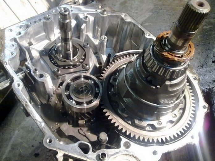
Most often, Aveo 1.2 car owners turn to repair because of the sounds that have appeared from the transmission. In particular, the photos below were taken when working on a gearbox on which the bearing bearings of the input and output shafts and differential are changed as a set. Plus the input shaft oil seal, CV joints (2 pcs.) And the gear selection block oil seal.
The Chevrolet Aveo gearbox is one of the key components of the car, responsible for converting the engine torque into the mechanical work of the vehicle wheels. The average duration of work before the first malfunctions appear is 50-60 thousand kilometers, after which motorists notice the first signs of wear of parts. Malfunctions are indicated by extraneous sounds when shifting gears, the appearance of oil stains under the car after parking. If you do not take timely measures, the node can completely fail.
A small video from the channel to allow you to get distracted from the problem of car repair:
A small video from the channel to allow you to get distracted from the problem of car repair:
- CHEVROLET Aveo gearbox replacement and repair
- replacement and repair of the CHEVROLET Aveo box
- replacement and repair of manual transmission CHEVROLET Aveo
- replacement and repair of the CHEVROLET Aveo gearbox
- CHEVROLET Aveo transmission oil change
- clutch replacement CHEVROLET Aveo
- replacing the release bearing CHEVROLET Aveo
- CHEVROLET Aveo rear oil seal and crankshaft bearing replacement
- replacement of the input shaft oil seal and oil seals of the CHEVROLET Aveo drives
- replacement of the input shaft of the CHEVROLET Aveo manual transmission
- replacement of the secondary shaft of the manual transmission CHEVROLET Aveo
- repair of backstage gearbox CHEVROLET Aveo
- repair (argon welding) of the gearbox housing CHEVROLET Aveo
- repair of the secondary shaft of the CHEVROLET Aveo gearbox
- replacement of the fifth gear of the manual transmission (without removing the gearbox from the car) CHEVROLET Aveo
- repair of 1st and 2nd gear of CHEVROLET Aveo
- repair of 3rd and 4th gear CHEVROLET Aveo
- repair of 5 gear CHEVROLET Aveo
- buy gearbox CHEVROLET Aveo
- buy manual transmission CHEVROLET Aveo
- will buy a box of CHEVROLET Aveo
- buy gearbox CHEVROLET Aveo
Call us to choose a time for manual transmission diagnostics and repairs in a gearbox repair workshop. An appointment in advance will allow you to find the most convenient solution, we are always ready to meet the wishes of the client.
In our specialized workshops for the repair of manual gearboxes of CHEVROLET Aveo gearboxes, high-quality service, diagnostics and repair of all types of gearboxes are carried out. We offer an honest service for your repair. Your presence is obligatory at all stages of diagnostics and repair of the CHEVROLET Aveo gearbox; all work and accessories are coordinated. The term for overhaul of the gearbox is from 0.5 to 1 working days (if the necessary parts are available).
We have round-the-clock line consultations on the repair of manual transmissions of gearboxes (8 965 126 13 83) and delivery for repair on a tow truck (8 926 167 15 40). A tow truck for manual transmission repairs is provided for a fee (within the MKAD - 3000, outside the MKAD by agreement).
The cost of work during the overhaul of the CHEVROLET Aveo checkpoint is 10,000 rubles (input and output diagnostics, removal and installation of the gearbox, disassembly and assembly, weekend test drive) + the cost of components.
Input diagnostics is carried out with the obligatory presence of the owner of the car within 30 - 40 minutes after removing the gearbox from the car (inspection, disassembling the manual gearbox, flushing the inner case of the gearbox from metal shavings, disassembling the shafts).
Removal of the gearbox from the car, disassembly and troubleshooting takes place on the day of the request for repair.
The warranty for the repair of the gearbox of the CHEVROLET Aveo gearbox is from 1 to 12 months or 60,000 km of run (set individually for each car - depending on the components during the repair).
The constituent components of the gearbox still have a certain resource, despite the fact that the gearbox usually lives up to 100 thousand km or even more. Of course, it all depends on the level and driving style of the driver.

The first symptom of a worn gearbox is a crunching sound when shifting gears. This indicates poor contact of the gears and sooner or later the box will completely break down. The second symptom is gear out. When you turn on, for example, the fifth and after a while it knocks out to neutral. Also, a symptom can be taken into account the heavy engagement of the first two gears, but this is more a helicopter than the gearbox itself.
It is also worth paying attention to oil leakage from the box, because if there is no oil, then all of the above symptoms are justified by this factor. If the oil does not flow out, then you will have to change the worn out parts of the gearbox itself. I personally recommend doing this procedure with someone experienced in box repair. You can confuse and break a lot yourself, which will lead to an even higher cost of repairs.
It can take a whole day to dismantle the gearbox, since it takes a very long time to remove it from the mountings, not to mention the need for an assistant, since the gearbox weighs a lot.
- Pliers.
- Mandrel.
- Support.
- Rags.
- Container for old oil.
- Lifting box.
- Key set (for 12, 14 and 19)
- Ratchet.
- Set of heads.
- Screwdriver Set.
- New oil for the box.
- Container for coolant.


- Remove the engine cover by unscrewing the 4 securing bolts.
- Remove the battery by first disconnecting the two terminals + and - from it.
- Remove the two bolts securing the fuse / relay box.
- Take the unit slightly to the side (to the tanks), but do not disconnect the wires.
- Unscrew the battery shelf.
- Disconnect the wires from the ignition coil by squeezing the clips with your fingers.
- Disconnect the crankshaft position and oxygen concentration sensor wires.
- Disconnect the pads from the bracket on the gearbox. To do this, you need to squeeze their antennae.
- Disconnect the wires from the speed sensor and from the reversing light switch. The same thing is to squeeze the latches.
- Drain the coolant into a prepared container.
- Drain the oil from the gearbox into a previously prepared container.
- Disconnect the heater radiator hose to the water distribution pipe. To do this, it is necessary to rip off the clamp (after mounting, it is necessary to install a new clamp).
- Disconnect the coolant radiator hose from the water distribution pipe. The same is to rip off the clamp.
- Dismantle the starter (its shields can still supply voltage and shock, so be careful, I pricked myself)
- Put the wires aside so that they do not interfere with work.
- Remove the front wheel drives.
- Move aside the clutch release cylinder. In this case, the hydraulic hose must be attached. To move the cylinder, you need to unscrew the two mounting bolts.
- Make marks on the steering rod and the tip of the gear lever, so that during installation you do not have to do the camber (I did it anyway).
- Disconnect the link and the end of the lever by unscrewing the clamp bolt.
- Remove the rear engine mount.
- Now you need to put supports under the oil sump and under the gearbox.
- Remove the three engine securing bolts to the gearbox housing.
- Unscrew the engine securing bolt to the engine mount.
- Remove the bracket.
- Remove the gearbox securing bolt to the cylinder block.
- Unscrew all 5 gearbox housing bolts, with one partner already holding the gearbox itself.
- Remove the bolt near the oil filter to the gearbox and the three securing bolts of the oil sump to the gearbox.
- Move the box back until the input shaft is disconnected from the driven disc.
- Remove the support from under the checkpoint.
- Together, as carefully as possible with a partner, remove the box to the floor. It is VERY heavy, so I recommend even removing it in three.
- It's easy to disassemble the box. Its two protective coatings are connected with a sealant. Get rid of the sealant with a knife, and that's it, the box is disassembled.
- Replace all necessary parts with new ones. Here I recommend contacting a specialist who probably knows what has worn out, since many parts may outwardly be new, but work poorly.
- Install the gearbox in the reverse order of removal.
- After installation, pour oil into the box.
- Fill with coolant.
- Adjust the gear shift drive.
- Check the functionality of the box.
I strongly advise against performing this procedure in a garage unless you have the appropriate experience. This could result in even more damage or the possibility of dropping the box. Everything that you do is at your own peril and risk, but in this situation it is easier to pay for the repair of the box and it is guaranteed to get the result.
Chevrolet Aveo (T-250) - Replacement of manual transmission bearings.
REPAIR OF THE F-16 BOX WITHOUT REMOVING FROM THE CAR Opel, Lanos, Nubira.
Oil change in the Aveo box
Configuring the backstage gearbox Chevrolet AVEO T200
Changing the oil in the box. Chevrolet aveo
Repair of Chevrolet Aveo 1 2 replacement of the fifth gear and replacement of the main pair
Repair of manual transmission Chevrolet Aveo in Moscow
Removing the Chevrolet Aveo gearbox for gearbox repair | Chevrolet aveo
The D16 transmission of the Chevrolet Aveo T250 is a fully synchronized five-speed constant mesh gearbox with a helical helical pair of main gears used in front-wheel drive vehicles.
A feature of the unit is the use of triple locking rings in the synchronizer mechanism of the 1st and 2nd gears.
The rest of the synchronizers are equipped with ordinary single locking rings.
Reverse is activated by means of a sliding idler gear, which, when engaged, engages with the gears of the driving and driven shafts.
The driven gear of the reverse gear is a ring gear on the 1st and 2nd gear clutch.
Fig. 3. Chevrolet Aveo gearbox device
Fig. 4. Support (housing) shaft bearings manual transmission D16
1. Jumper, 2 Fastening screw, 3. Fastening screw, 4. Retainer nut, 5. Bearing support, 6. Blocking mechanism stem, 7. Pin, 8. Stem, 9. Spring, 10. Plug, 11. Gear shift fork , 12. Gear shift pad, 13. Screw, 14. Cover, 15. Cover gasket, 16. Magnet, 17. Support gasket, 18. Support fastening screw to the body, 19. Cover fastening screw, 20. Cover fastening screw, 21 . Cover fixing screw, 22. Locking sleeves
Fig. 5. Gear shift mechanism
1. Gear lever, 2. Mounting screw, 3. Lever rod cover, 4. Clamp, 5. Fastening screw, 6. Intermediate gear lever, 7. Gear shift matching unit, 8. Pin, 9. Retaining ring, 10 Mounting screw, 11. 1st and 2nd gear shift fork, 12. 1st and 2nd gear shift rod, 13. Pin, 14. 3rd and 4th gear shift fork, 15. Shift rod shifting of 3rd and 4th gears, 16. Pin, 17. Slider for engaging 5th gear, 18. Stop of the gear shift rod, 19. Reverse gear shift fork, 20.Reverse gear shift rod, 21. Pin, 22. Gear shift rod, 23. Finger, 24. Shift lever cover, 25. Intermediate shift lever, 26. Gasket, 27. Spring, 28. Bushing, 29. Retaining ring, 30. Cover gasket, 31. Mounting screw, 32. Plug, 33. Plug, 34. Speedometer driven gear, 35. Mounting screw, 36. Differential cover gasket, 37. Differential cover, 38. Screw, 39. Reversing light switch, 40 . O-ring, 41. Pin, 42. Pin, 43. Sleeve, 44. Sleeve
Adjustment of the gearshift mechanism of the Chevrolet Aveo T250 gearbox
- Disconnect the negative battery cable.
- Place the gear shift lever in neutral.
- Loosen the clamping bolt of the gear shift drive rod clamp.
- Remove the adjusting hollow insert from the shift lever cover.
- Turn the stem and fix it by fully inserting the 5 mm pin into the hole.
- Disconnect the fastening of the lower edge of the gear lever gaiter.
- Pull the cover up to provide access to the shifting mechanism.
- Move the shift lever to the left of the neutral position.
- Insert a 5mm pin into the holes to ensure that the shift lever is aligned with its body.
- Tighten the rod clamping bolt to 14 Nm.
- Remove the locking pin from the adjustment hole.
- Remove the locking pin from the shift lever.
- Place the cover on the console.
Removal and installation of the shift lever
- Place the shift lever in neutral.
- Detach the cover from the console cover.
- Lift the cover up to open access to the gearshift lever mechanism.
- Remove the stop clamp of the control lever by rotating it. Remove the control arm from the shaft.
- Place the shift lever on the shaft.
- Install the stop clamp for the control lever.
- Rotate the stop clamp of the control lever to secure it.
Removal and installation of the body of the switching mechanism
- Remove the gear lever housing by unscrewing the fastening screws.
- Install the shift lever housing and tighten the mounting screws to 7 Nm.
- Adjust the gearshift mechanism.
Replacing the wheel drive shaft oil seal
- Remove the drive shaft oil seal.
- Install a new drive shaft oil seal using an oil seal installer and a hammer.
- Lubricate the sealing lip with gear oil.
Remove the battery and battery shelf.
Remove the control linkage.
Disconnect the reversing light switches electrical connector.
Disconnect the speedometer speed sensor electrical connector.
Remove the clutch slave cylinder.
Remove the three mounting bolts.
Remove the rear mounting bracket from the D16 gearbox.
Remove the rear damper block from the front beam.
Remove the two bolts securing the rear support.
Remove the three transmission upper mounting bracket bolts.
Remove the upper mounting bracket and intermediate drive shaft support.
Remove the three upper mounting bolts.
Remove the seven lower mounting bolts.
Remove the transmission. Only place the box in an upright position.
Move the machine away from the engine block. Lower the machine.
Installation of manual transmission Chevrolet Aveo 1.5
Install the transmission by inserting the input shaft into the splined hole of the clutch disc and connect it to the engine.
Install the seven bottom retaining screws and tighten.
Install the intermediate support and tighten the fastening screws to 55 Nm.
Install the mounting bracket and tighten the mounting bolts to 60 Nm.
Tighten the rear damping unit mounting bolts to 55 Nm.
Install the rear damping block on the front cross member and tighten the mounting bolts to 50 Nm.
Tighten the damping block union nut and bolt to 80 Nm.
Install the clutch slave cylinder and tighten the bolts to 20 Nm.
Connect the electrical connector of the speedometer speed sensor.
Connect the reversing light switch electrical connector.
Remove the engine support tool.
Install the transmission linkage.
Install the battery shelf and battery.
The Chevrolet Aveo D16 gearbox is a fully synchronized five-speed manual gearbox with constant mesh gears and a helical helical pair of main gears used in the transmission of front-wheel drive vehicles.
A feature of the Chevrolet Aveo D16 gearbox is the use of triple locking rings in the synchronizer mechanism for 1st and 2nd gears.
The rest of the synchronizers are equipped with ordinary single locking rings.
Reverse is activated by means of a sliding idler gear, which, when engaged, engages with the gears of the driving and driven shafts.
The driven gear of the reverse gear is a ring gear on the 1st and 2nd gear clutch.
Fig. 3. Chevrolet Aveo gearbox device
Fig. 4. Support (housing) of the bearings of the shafts of the gearbox D16 Chevrolet Aveo
1. Jumper, 2 Fastening screw, 3. Fastening screw, 4. Retainer nut, 5. Bearing support, 6. Blocking mechanism stem, 7. Pin, 8. Stem, 9. Spring, 10. Plug, 11. Gear shift fork , 12. Gear shift pad, 13. Screw, 14. Cover, 15. Cover gasket, 16. Magnet, 17. Support gasket, 18. Support fastening screw to the Chevrolet Aveo manual transmission case, 19. Cover fastening screw, 20. Fastening screw cover, 21. Cover fastening screw, 22. Locking sleeves
Fig. 5. Chevrolet Aveo gearshift mechanism
1. Gear lever, 2. Mounting screw, 3. Lever rod cover, 4. Clamp, 5. Fastening screw, 6. Intermediate gear lever, 7. Gear shift matching unit, 8. Pin, 9. Retaining ring, 10 Mounting screw, 11. 1st and 2nd gear shift fork, 12. 1st and 2nd gear shift rod, 13. Pin, 14. 3rd and 4th gear shift fork, 15. Shift rod shifting of 3rd and 4th gears, 16. Pin, 17. Slider for engaging 5th gear, 18. Stop for shift rod, 19. Fork for shifting reverse gear, 20. Shifting rod for reverse gear, 21. Pin, 22. Shift rod, 23. Pin, 24. Shift lever cover, 25. Intermediate shift lever, 26. Gasket, 27. Spring, 28. Bushing, 29. Retaining ring, 30. Cover gasket, 31. Fastening screw, 32. Plug , 33. Plug, 34. Driven gears of the speedometer, 35. Fastening screw, 36. Differential cover gasket, 37. Differential cover, 38. Screw, 39. Reversing light switch, 40. Pack seal ring, 41. Pin, 42. Pin, 43. Sleeve, 44. Sleeve
Adjusting the gearshift mechanism of the Chevrolet Aveo gearbox
- Disconnect the negative battery cable.
- Place the gear shift lever in neutral.
- Loosen the clamping bolt of the gear shift drive rod clamp.
- Remove the adjusting hollow insert from the shift lever cover.
- Turn the stem and fix it by fully inserting the 5 mm pin into the hole.
- Disconnect the fastening of the lower edge of the gear lever gaiter.
- Pull the cover up to provide access to the Chevrolet Aveo gearshift mechanism.
- Move the shift lever to the left of the neutral position.
- Insert a 5mm pin into the holes to ensure that the shift lever is aligned with its body.
- Tighten the rod clamping bolt to 14 Nm.
- Remove the locking pin from the adjustment hole.
- Remove the locking pin from the shift lever.
- Place the cover on the console.
Removing and installing the Chevrolet Aveo gearbox lever
- Place the shift lever in neutral.
- Detach the cover from the console cover.
- Lift the cover up to expose the Chevrolet Aveo gearshift lever mechanism.
- Remove the stop clamp of the control lever by rotating it. Remove the control arm from the shaft.
- Place the shift lever on the shaft.
- Install the stop clamp for the control lever.
- Rotate the stop clamp of the control lever to secure it.
Removing and installing the gearshift housing for the D16 Chevrolet Aveo
- Remove the gear lever housing by unscrewing the fastening screws.
- Install the shift lever housing and tighten the mounting screws to 7 Nm.
- Adjust the gearshift mechanism of the Chevrolet Aveo gearbox.
Replacing the wheel drive shaft oil seal
- Remove the drive shaft oil seal.
- Install a new drive shaft oil seal using an oil seal installer and a hammer.
- Lubricate the sealing lip with gear oil.
Removing the Chevrolet Aveo gearbox
Remove the battery and battery shelf.
Remove the Chevrolet Aveo gearbox control linkage.
Disconnect the reversing light switches electrical connector.
Disconnect the speedometer speed sensor electrical connector.
Remove the clutch slave cylinder.
Remove the three mounting bolts.
Remove the rear mounting bracket from the D16 Chevrolet Aveo gearbox.
Remove the rear damper block from the front beam.
Remove the two bolts securing the rear support.
Remove the three Chevrolet Aveo transmission upper mounting bracket bolts.
Remove the upper mounting bracket and intermediate drive shaft support.
Remove the three upper mounting bolts.
Remove the seven lower mounting bolts.
Remove the Chevrolet Aveo gearbox. Place the transmission only in an upright position.
Move the transmission away from the engine block.
Installing the Chevrolet Aveo gearbox
Install the Chevrolet Aveo transmission by inserting the input shaft into the splined hole of the clutch disc and connect it to the engine.
Install the seven bottom retaining screws and tighten.
Install the intermediate support of the D16 Chevrolet Aveo gearbox and tighten the fastening screws to a torque of 55 Nm.
Install the mounting bracket and tighten the mounting bolts to 60 Nm.
Tighten the rear damping unit mounting bolts to 55 Nm.
Install the rear damping block on the front cross member and tighten the mounting bolts to 50 Nm.
Tighten the damping block union nut and bolt to 80 Nm.
Install the clutch slave cylinder and tighten the bolts to 20 Nm.
Connect the electrical connector of the speedometer speed sensor.
Connect the reversing light switch electrical connector.
Remove the engine support tool.
Install the Chevrolet Aveo transmission linkage.
Install the battery shelf and battery.
| Video (click to play). |
Check the oil level in the Chevrolet Aveo gearbox.

