Repair of the gearbox of the K 701 tractor is necessary if an increased heating of the installed gearbox began to be noted. As a rule, in the transmission there is a low level of lubrication. Fluid leakage from the side of the drive axles occurs due to an increased oil level. It could also be the result of a dirty breather. The consequence of the fact that the owner of the car is faced with a fuel leak may be worn out oil seals. With this in mind, the tractor driver must monitor the oil level.
In case of insufficient pressure in the hydraulic system, the gear coupling, roller, bearing must be checked. It is worth inspecting the condition of the oil pump. If the pump has lost its performance, this element must be replaced with an option that will suit the Kirovets working system in terms of its characteristics.
VIDEO
Spontaneous gear shifting is another problem that can be remedied by replacing worn parts or by adjusting the drive.
Driving the K 700 and other modifications will be difficult if the gearbox pressure drops. There are several reasons for this, starting with the clogged filter, ending with a breakdown of the gearshift mechanism.
The gearbox on the tractor provides efficient starting and stopping of the machine. That is why it is necessary to take proper care of it. Ignoring any malfunctions with the transmission system can lead to spontaneous movement of special equipment, creating an emergency. Given this, Kirovets must be periodically subjected to full diagnostics. This procedure includes checking the components of the tractor. First of all, these are mechanisms related to the engine system, transmission.
The duration of the transmission system operation is influenced by the amount of fuel added to the speed box.For gearboxes on K 700 (701), oils should be chosen that retain their performance for a long time. It is allowed to refuel the main and final drives with Nigrol.
It is possible to replace fuel at Kirovts either independently or entrust this procedure to mechanics who have experience in doing these works. At the end of the box repair, professional service centers must issue a guarantee for the work done.
For preventive purposes, it is necessary to clean the oil-conducting channels of the cross. All worn out or deformed components of the gearbox must be replaced. Better to give preference to original parts. This will be a guarantee that they do not prematurely leave the working state. As a rule, the need to disassemble the gearbox arises as a result of prolonged operation of the tractor.
When installing new parts into the system, certain rules must be followed. Particularly when insertion into the drive shaft housing is required, the bushing is likely to be damaged. That is why it is advisable to entrust the work of replacing individual mechanisms to experienced craftsmen. A special stand is required to repair an engine or transmission. The device removed from the tractor and fixed on the stand makes it possible to simplify the process of carrying out restoration work.
Thus, the installed gearbox on the tractor ensures efficient movement of the vehicle, regardless of the choice of speed mode. The box has several drive stages. During the repair of the gearbox, it is required to disassemble it, wash its constituent parts, troubleshoot, and reassemble.
This tractor has a manual transmission, which has hydraulic clutch control. It is they who provide gear shifting without interrupting the power flows within the same mode. With the help of the checkpoint, you can change the speed of the tractor forward, as well as backward.
When the tractor is started from the tug, and the engine is not running in it, then the gearbox transmits torque to the pump that controls the steering from the wheels, as well as to the hitch pump. With the help of the gearbox, you can turn off the rear axle, because it transfers rotation to the power take-off shafts from the engine itself.
Sometimes it is necessary to repair the K 700 gearbox, which is located in front of the tractor half-frame, right on the damping shock absorbers themselves. Special adjusting plates are placed under them, which ensure the alignment of the output shafts of the tap-changer, as well as the drive shafts of the gearbox.
The hydraulic system of the gearbox turns on the clutches of the drive shaft, brakes, as well as the PTO clutch. It serves to lubricate the parts of the drive shaft with gearbox gear parts, PTO coupling and on-load tap-changer.
During the repair of the K 700 gearbox, in order to eliminate the decrease in pressure that can be observed in the clutches of the fourth, as well as the first gear in the drive shaft, it is necessary to perform the following actions:
- unscrew the end nut, remove the oil line and springs, flush it all and replace the broken rubber rings in the oil line;
- remove the flange, unscrew the set screw, remove the left support together with its collar, the ring, the cast-iron sealing ring with its collar. All defective parts in the mechanical seal must be replaced. The ring with its lip seals prevents any mechanical seals from being jammed during assembly and operation of the drive shaft.
To eliminate the pressure drop in the clutches of the second, also third gears, which are in the drive shaft, it is necessary to remove from above the part of the gearbox crater with the drive shaft itself. Before opening the gearbox by repairing the K 700 gearbox, it is necessary to unscrew the three bolts that are attached to the tachospeedometer gearbox on the lower part of the crankcase, and then slightly loosen the two bolts attached to the upper part of the gearbox crankcase (all this is done to avoid rupture gaskets).In the process of assembling packs of discs with clutches of the drive shaft, it is necessary to use technological bolts when tightening the pack, they must be screwed into those holes that are in the pressure discs through the holes in the inner drums. The clutches of the gears on the drive shaft are separately assembled, closing with a spring ring, which eliminates the opening of the joints, as well as a decrease in pressure due to end wear.
The clutches are forced to ensure the normal rotation of the shafts driven by hand when the clutches on the outer drums are stationary.
After the drive shaft is assembled, it is necessary to press all the clutches on special stands for three minutes with engine oil, at a temperature of about fifty degrees, the pressure being one mega pascal. Oil pressure must not be allowed to drop. When the pressure drops, it is necessary to make sure that the pressure discs return to their original position immediately after the springs are directly applied to them.
Immediately after the gearbox repair work has been completed, it is imperative to run in the tractor.
In this article we will consider the device and the principle of operation of the gearbox of the Kirovets K-700 and K-701 tractors, since their structure is completely identical. We will also give the main points in the adjustment, maintenance and repair of this mechanism.
The gearbox of the K-701 tractor is a four-band, with constant mesh gears, with mechanical range switching when the tractor is stopped and hydraulic gear shifting within each range without stopping the tractor.
The K-701 gearbox provides 16 forward speeds and 8 reverse speeds.
The gearbox housing rests through shock absorbers on four brackets of the tractor's front half-frame and consists of upper and lower halves - a spacer and a pallet. A pedal and control levers are mounted on the crankcase.
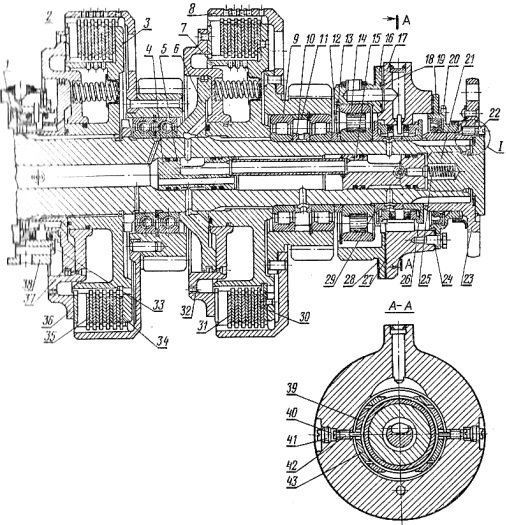
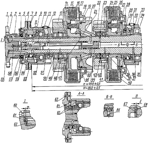
A schematic section of the gearbox (by shafts) is shown in the diagram below. The gearbox has four main shafts. The primary (drive) shaft 39 is driven by the flange 40 of the front propeller drive. Below there are intermediate 36 and cargo 31 shafts. In the lower tide, there is a transfer case 24 with a flange 25 of the front drive axle drive and 18 of the rear drive axle.
On the cylindrical surface of the driving (inner) drum there are splines along which five steel toothed friction discs 9 can move. They are located between six toothed discs 10 sliding along the splines of the outer (driven) drum. A pressure plate 12 is installed on the hub of the driving drum, which compresses a package of frictional squeaks under oil pressure.
Oil enters the cavity A of the extreme hydraulic clutches through the oil lines 7, and it is fed into the same cavities of the middle clutches through the channels from the middle shaft support. Sealing legs 11 do not allow oil to flow out of cavity A, but part of it passes through throttling holes B into cavity C of the inner drum.
From here, through the holes D in the drum, the oil is thrown onto the clutch discs, and then through the holes D of the outer drum it is drained into the gearbox housing. When the clutch is disengaged, the springs 8 squeeze the disc 12 from the friction disc pack, displacing the oil from the cavity A back through the same channels.
The driven drums of the 1st and 4th gears are equipped with synchronizer brakes. The oil pressure presses the brake pads against the drums and stops them together with the gears attached to them. When there is no oil pressure in the cavities of the synchronizing brakes, their springs move the brake pads away from the drums.
Gears 4, 7, 8 and 10 of IV, III, II and I gears are in constant mesh with the gears of the intermediate shaft. Gear 5, attached to the driving part of the clutch 4, serves to drive the oil pump shaft. On the left end of shaft 1, a helical gear wheel 1 is installed. It rotates the tachospeedometer with the help of a flexible shaft (cable).
Intermediate 36 rotates in two roller and one ball bearings. Seven gears are clamped on the spline shaft with spacer sleeves: four (37, 34, 13 and 12) rotate by the gears of the input shaft, and gears 35 of the reduced speed range and 14 of the row of high speeds are in constant meshing with gears 28 and 26 of the cargo shaft.
The gear 38 of the intermediate shaft also transmits the rotation to the cargo shaft 31, but through the intermediate gear 32, and therefore in the opposite direction. This is how reverse speeds are obtained. Cargo 31 is mounted on two ball and one roller bearings. Gears 30, 28 and 26 with internal toothed rims are freely supported on ball bearings, and the gear couplings 29 and 27 can slide along the splines of the shaft.
Moving the clutch 29 to the left, gear 30 is connected to the cargo shaft, gears 28 or 26 of modes of reduced or increased operating and transport speeds are connected. Gears 15 and 16 are installed on the slots of the cargo shaft between the spacer sleeves. They drive the transfer shaft into rotation through gears 23 or 20.
Transfer case 24 through the flange, 25 constantly rotates the mechanisms of the front drive axle. It is supported by roller and ball bearings. Between them, on ball bearings, gears 23 and 20 with side toothed rims rotate freely, and gear 22 is installed on the splines of the shaft. The gear clutch 21, sitting on the gear 22, can take two positions: left, when it connects the small gear 23 to the shaft, and right, when it connects gear 20 to the shaft.
The mechanism 18 of the drive of the rear drive axle rests at the front on a needle bearing installed in the bore of the shaft 24, and at the rear on a ball bearing fixed in the bushing.
The gearbox oil pump drive unit is located to the right of the input shaft (top in the diagram) and rotates on two ball bearings. Gears 2 and 6 with outer and inner toothed rims are mounted on the shaft on their bearings. Coupling 3 slides between the gears along the shaft splines. Installed in the right position, the coupling connects gear 6 to the shaft, and rotation is transmitted to the shaft through gear 5 of the input shaft from the diesel engine.
Taking the left position, the clutch connects part 1 with gear 2, and then it rotates from the wheels of the tractor. 1 its position, the clutch is set when towing the tractor to drive the gearbox pump, as well as the pump of the hydraulic steering control system of the tractor. Let's follow the diagram through which the rotation is transmitted from the input shaft to the dispensing mechanism.
1 and 4 - driving gears of II and I gears; 2 - driven drum; 3 - driving drum; 5 and 6 - nut and spring for pressing the oil line; 7 - oil pipeline; 8 - clutch release spring; 9 and 10 - driving and driven clutch discs; 11 - sealing rings; 12 - pressure disk; 13 - middle disc; 14 - drive shaft; A - cavity of the hydraulic clutch; B - throttle hole; B - the cavity of the inner drum; Г — holes in the driving drum; D - holes in the driven drum; E - channel for supplying oil to the oil line.
The primary shaft 39 is hollow, rotates on three bearings: ball and two roller. Four hydraulic clutches are mounted on the shaft. Their driving drums 3 (see diagram) are fixedly mounted on the splines of the shaft, and the driven drums 2 are attached to gears rotating freely on two roller (extreme couplings) or ball (middle couplings) bearings.
Range of working speeds: primary 39 - gears of one pair of the included transfer (4-37, 7-34, 8-13 or 10-12);
The range of reduced operating speeds: primary 39 - a pair of gears of the included transfer - 36 - gears 35 and 28;
Range of transport speeds: 39 - a pair of gears of the included transfer;
The range of increased transport speeds: shaft 39 - a pair of gears of the engaged gear - shaft 36 - gears 14 and 26 - shaft 31 - gears 15 and 23 - shaft 24.
Reverse: shaft 39 - a pair of gears of the engaged gear - shaft 36 - gears 38, 32 and 30 - shaft 31 - gears 16 and 20 (high range) or 15 and 23 (low range) - shaft 24.
The gears are switched on or off while the tractor is in motion using hydraulic clutches that transfer rotation from the primary to the intermediate through the hydraulic system.
Our company sells spare parts for various types of special equipment, trucks and agricultural equipment of domestic and foreign production, including spare parts for transmission of the tractor K-700 . One of the directions of the enterprise's work is the repair and maintenance of engines, transmissions, steering, braking systems, running gear, hydraulic and electrical equipment. Working with us, you are guaranteed to receive an individual approach and expert advice, as well as high-quality spare parts and components at the lowest prices.
Repair and adjustment of the switch box
K-700 tractor gearbox Petersburg Tractor Plant consists of:
crankcase ,leading shaft ,gear part,
control drives,
hydraulic system.
To fulfill the technical assignment - repair and adjustment KPP K-700 - do the following:
disassembly of the gearbox;
washing of units and parts;
troubleshooting;
complete set instead of faulty parts;
repair of parts fit for restoration;
assembly;
running-in, testing (drive shaft, gearbox).
Schematic representation KPP tractor K-700
lever arm toggle gears K-700 ;Malfunctions and repairs of the check point of the K-700 PTZ tractor.
Malfunction
1. Difficulty shifting the gears of the K-700 tractor:
- incomplete disengagement of the clutch (the clutch "leads");
Adjustment of the free wheeling of the K-700 clutch pedal, or if there are damaged parts, they are changed,
Replace unusable parts.
2. Increased noise of the gearbox of the K-700 tractor:
- there is not enough oil in the gearbox;
Fill in oil up to the level of the control hole.
Replacing defective bearings.
Replacing defective gears.
3. Spontaneous disengagement of gears while driving :
- uneven wear of the teeth of gear couplings;
Replacement of defective parts and bearings.
4. Spontaneous switching off of ranges in the range multiplier of the K-700 tractor:
- compressed air enters the cylinder cavity, which is opposite to the included gear;
Replacing defective o-rings and air distributor inlet valve.
They change crackers, adjust the stroke.
5. "Non-inclusion" or delayed inclusion of ranges in the range multiplier with the neutral position of the lever. The lamp does not go out for a long time, air comes out through the breather of the top cover:
- the membrane of the air distributor is damaged;
Replacing a damaged membrane.
Replacing the O-rings.
6. Passing air through the breather of the air distributor with the gear engaged in the main box:
- wear of the inlet valve rubber;
Replacement of defective parts.
Adjusting the gearbox tractor K-700 PTZ
1. Testing and adjustment of the gearbox after assembly is performed at the stand.
2.In crankcase boxes gears K-700 Fill with engine oil M108 up to the mark of the upper control hole.
3. To fill the oil lines with oil, turn leading shaft boxes gears K-700 (900 + 70 rpm for 1 minute). Add oil if necessary.
4. Run-in at neutral position of the control levers (900 + 70 rpm, 5 min.). When running in, do:
adjustment of the pressure reducing valve for a preliminary pressure of 0.85 MPa (8.5 kgf / cm 2;
check for leaks from seals and external connections of oil lines;
checking the pressure of the oil supplied to the lubrication, its value must be at least 0.05 MPa (0.5 kgf / cm 2);
checking the oil pressure, which goes to the power take-off mechanism and the synchronizer brake, the indicator of this parameter should be 0.85 MPa (8.5 kgf / cm 2);
5. After running in in neutral gear, you need to run in in 1st, 2nd, 3rd, 4th gears for 2 minutes for each (the rocker lever is in neutral position, oil pressure is 0.85 MPa (8.5 kgf / cm 2).
6. Running in the gearbox at a speed of 1700 ± 70 rpm of the crankshaft (6 minutes in all gears of I and IV modes, and 3 minutes in all gears I and II of reverse modes). Within the range of each of the modes, gear changes are performed sequentially - from lowest to highest. The transition from mode to mode is carried out in neutral gear, the rotational speed does not exceed 900 rpm. The oil temperature is not more than 90 o C.
There should be no oil leakage from the external connections of the oil lines and seals. The operation of the gears is smooth, with a uniform noise. Fractional rolls and separate blows should not be. After finishing testing and adjustment, the ends of all holes are closed with technological plugs. Check how the fastening of the upper half of the crankcase to the lower one is tightened.
Shafts of the gearbox of the tractor K-700 PTZ
1. Shaft of pumps of gearbox K-700
13-, 14- bevel gear;
2. The distributor shaft of the gearbox of the tractor K-700 PTZ
3-, 6- mobile gear clutch;
3. Cargo shaft of the check point of the K-700 tractor
4. Intermediate shaft of the gearbox of the tractor K-700
2-, 3 -, 5 -, 6 -, 7 -, 8 -, 9 - gear;
5. Leading shaft of the check point of the K-700 tractor
Good day to all, I am repairing the checkpoint to 701 and to 744.
I can help with repairs
There are no questions. Then think aloud. For what reasons most often the K 701 and K 744.1 gearboxes fail, the bearings of 1st and 4th gears collapse. 2 Pressure disappears in 2nd and 3rd gears (1 and 4 do not count, they can be done without removing the gearbox). 3 chipped teeth of gears. 4 warping of discs at normal pressure. 5 knocks out modes. 6 gear change mechanism, why does it fail. 7 Troubleshooting and restoration of some parts. 8 Strengthening the power shaft. 9 The handbrake on the 701 is simple, and the checkpoint runs longer. Why this happens and how to fix it I will describe here, if someone needs it, while there is little work. I can’t write quickly, but I'll do it a little.
If you need to figure out something for a long time, then it is better by phone, not very expensive.
Well, write to me personally, it is interesting to 701 I recently have 2 years and everything else Case is from 120 horses to 280
Michal Fedorovich write interesting!
1 There is no handbrake on the 701, and therefore many use neutral after stopping at the MPP as a handbrake. small diameter compared to 4 lane.and with each braking, the drum presses on its side, and roller bearings do not like this and play appears and collapses over time, so do 4 lane. I put ball bearings. The conclusion is simple, you need to use this neutral for its intended purpose, that is, stopped the shaft turned on the mode and turned off and that's all If there is no way out, you need to attach the unit, and the tractor is rolling. I pulled up the brake, increased the speed to 1200 rpm (so that the brakes did not slap on the shaft, but kept it straight) hooked up and turned off. And we do the handbrake, we take an energy accumulator from KAMAZ and put it instead of the standard brake chamber, add hoses to the cab and a parking brake control valve from KAMAZ. By the way, K-744 is also from the factory.
As for the handbrake, I did so, it stands rooted to the spot and the parking is turned on only to switch ranges, I agree with you about the bearings of 1st and 4th gear
2. Pressure disappears in 2nd and 3rd gears. The most common reasons. The pressure on these gears is kept at 6 positions, and the appearance of a leak on one is fraught with a pressure drop. we get axial runout of the shaft, since the gearbox weighs 1000 kg, it is noticeable. Since the shaft is held in the housing by one pin with a diameter of 12 mm, the support bearing, rubber bands holding the oil supply pressure and sliding rings begin to break. As a result, a quick repair if there is a faulty the bearing of the support is the same. The bearing can be checked visually. On a running tractor, one looks behind the gearbox, and the other, when the modes are off, switches from 2nd to 3rd gear and vice versa. If the shaft flange moves, then the bearing is broken and you can already save money for repairs. Price elimination of these causes changes every day. And also when assembling the middle support, the rings with the cuffs should rotate freely in the support. Elimination - a good repair kit of rubber bands.
Disassembly and assembly recommendations. Device, repair, maintenance of tractors K700A K701 K702
Repair , service and device , disassembly and assembly recommendations tractors "Kirovets" K700A, K701, K702 ... Schemes, sketches, figures, drawings, tables.
The site contains the technical and economic indicators of the K-700A, K-701 and K702 tractors. The features of their operation, maintenance and storage are discussed. Recommendations for disassembly and assembly of the main mechanisms and troubleshooting are given.
The tractor is a complex design. The main units are located on the bearing front and rear semi-frames, which are interconnected by vertical and horizontal hinges. The transmission uses a multi-stage, manual, four-speed gearbox with power shifting without interrupting the power flow within the range.
The diesel engine of the K-701 tractor is equipped with an automatic thermal regime control system.
Hydraulic steering systems of tractors are equipped with devices that ensure a constant speed of relative movement of the half-frames.
The use of an automatic wheel locking mechanism, tires of low specific pressure and increased carrying capacity improved maneuverability and cross-country ability.
A spacious, bright cab with heating in the cold season, with powerful ventilation, a sprung seat for the tractor driver, low effort on the control levers, a small percentage of dust content in the air, low noise level and effective thermal and sound insulation create good working conditions for the tractor driver.
Equipping tractors with a reverse and a creeper has expanded their application and use in road construction, loading, reclamation and earthmoving operations, as a result of which the annual employment of machines and the economic efficiency of their use have significantly increased. They can work with loading, bulldozing, scraper and snow removal equipment.
A characteristic feature of the new Kirovets tractors is a high degree of unification of units, assembly units and parts, which simplifies the organization and conduct of repairs, and reduces the range of spare parts.
OJSC "Agroremont" high-tech enterprise producing overhaul and current repairs of tractors "Kirovets" St. Petersburg plant.
overhaul of the gearbox of the gearbox of the Kirovets tractors, one year or 1000 hours of warranty
repair of basic parts and assemblies
There is a repair fund, check by phone 8- (928) -601-44-82.
Actual prices in the price list section.
The list of works performed during the overhaul of the gearbox of the gearbox
Disassembly of the checkpoint into units. Assembling the checkpoint from units.
Disassembly of the oil pump gear drive. Assembly.
Disassembly of the control drive of the cargo shaft coupling. Assembly.
Dismantling the drive shaft. Assembly.
Disassembly of the switching mechanism. Assembly.
Testing the oil pump on the bench.
Disassembly of the stage. Stage assembly.
Dismantling the parking brake band. Assembly.
Dismantling the oil pan. Remove and install oil pump.
Disassembly of the control drive bridges. Assembly.
Dismantling the gearbox housing. Assembly.
Dismantling the gearbox oil filter. Assembly.
Place the checkpoint on the stand. Attach the cardan shafts, fill the gearbox with oil. Remove and rinse the filter and install the filter on the mesh.
Accumulator (assembly, disassembly)
Cut the threads of the housing holes.
Cleaning the old gasket.
Collecting.
Overhaul of the gearbox of the K-700A, K-701, K-744 R-1 tractors
Purpose and device. The gearbox is designed for starting and stopping the tractor, for changing the speed and direction of movement, as well as the tractive effort on the hook, for transferring engine power to the power take-off mechanism, disabling the rear drive axle and driving the gearbox oil pump when towing the tractor.
Transmission - mechanical, with constant mesh gears, 16-speed (four-mode), with hydraulic control of four clutches and mechanical control of gear clutches. All gears are spur gear. The numbers of teeth and gear meshing modules are shown on the kinematic diagram of the transmission. The values of all speeds of movement and pulling forces on the hook are given in Appendix 1.
The gearbox consists of a crankcase, a drive shaft, a reduction part, control drives and a hydraulic system.
We make overhaul of the Kirovets checkpoint of tractors K-700, K-701, K-702, K-703, K-744R1, K-744R2, K-744R3.
What does the overhaul of the Kirovets K700 checkpoint include?
2. Rejection of out-of-order spare parts, inspection of the housing for wear, wear of mating surfaces and cracks;
3. Assembling the checkpoint with the installation of new spare parts;
4. Replacement of rubber goods, gaskets, bearings;
5. Run-in of the checkpoint at the stand, measurements of operating parameters;
During the repair process, the following assembly units and parts that have not passed the defect must be replaced: Crankcase 700А.17.01.255-2, Crankcase 700А.17.01.256-1
Driving shaft К-700 and К-701, 700А.17.01.010-2, Body 700.17.01.253-1, Gear shifting mechanism 700А.17.02.000-2, Rack 700А.17.02.036-1, Oil intake 700А.17.04. 030, Elbow 700А.17.04.027, Pipeline 700А.17.04.040, Bushing 700А.17.04.017, Section 700.17.16.170, Plug 700.17.16.103, Spring 700.17.16.105, Valve 700.17.16.107, Saddle 700.17.16.108, Kulisa 700А .17.17.000, Drum 700A.17.01.417-1, Drum 700A.17.01.520, Drum 700A.17.01.041-4, Drum 700A.17.01.059-2, Drum 700A.17.01.055-3, Drum 700A .17.01.540-1, Disc 700A.17.01.037-1, Disc 700A.17.01.038-1, Ring 700.17.01.458-1, Ring 700.17.01.024-2, Ring 700.17.01.023-2, Ring 700A.17.01 .016-1, Bushing 700.17.01.022-2, Ring B125, B110, B130, Ring 700A.17.01.101-1, Bushing 700.17.01.062, Screw 700.17.01.428, Ring 700A.17.01.497, Ring 700.17.01.459, Oil seal 2.1х75х110-4, Complete repair kit for cuffs and rubber rings 1307, Pump НМШ25, Shock-absorber AKSS-220М, 700.00.17.170
Video (click to play).
Soyuz-Truck, Cheboksary, offers cooperation in the supply of spare parts for tractors Kirovets (K700, K-701, K700, K701, K-702, K-703, K-744R1, K744R2, K 744R3), KhTZ (T- 150, T150, T-151, T-156, T157, T158, HTZ-16131, HTZ-17221, HTZ-17321). Parsing.

