In detail: do-it-yourself gearbox repair 2108 from a real master for the site my.housecope.com.
Remove dirt and wash the outside of the gearbox.
2. Place the transmission straight up.
3. Remove the six nuts securing the rear cover.
4. Remove the mounting bolt and.
5. ... remove the clutch cable bracket.
6. Gently hit the back cover with a rubber mallet.
Remove the gasket carefully, as an undamaged gasket can be re-installed during assembly.
7. Remove the rear cover from the Lada Samara gearbox housing.
8. Remove the gasket.
9. Engage 3rd or 4th gear.
10. Remove the 5th gear fork bolt and engage 5th gear.
To secure the shafts from turning, it is necessary to simultaneously engage the 5th gear and the 3rd or 4th gear. To engage 5th gear, move down the synchronizer clutch together with the fork (the fork fastening bolt must be unscrewed) so that the splines of the clutch mesh with the gear rim of the gear.
11. Make sure the shafts do not turn.
12. Loosen the nut on the output shaft.
13. Unscrew the nut on the output shaft.
The nuts on the shafts are tightened with a high torque, so you need to apply a lot of effort to loosen.
14. Unlock the nut on the input shaft.
15. Unscrew the nut on the input shaft.
Remove the synchronizer carefully. Make sure that the synchroniser sleeve does not come off the hub: the spring-loaded synchroniser locking balls may crumble.
16. Use screwdrivers to hook the 5th gear synchronizer of the VAZ 2109 onto the hub.
17. ... and remove it together with the plug. Remove the plug from the coupling.
18. Remove the 5th gear synchroniser locking ring.
| Video (click to play). |
19. Use a screwdriver to hook up the 5th gear driven gear.
20. ... and remove it from the secondary shaft of the samara fret.
21. Remove the needle bearing thrust washer.
22. Remove the 5th gear needle bearing.
23. Use a screwdriver to hook up the 5th gear drive gear.
24. ... and remove it from the input shaft.
25. Use an impact screwdriver to remove the four screws holding the bearing plate.
26... Remove the bearing plate.
27. Pick up with screwdrivers and remove the 5th gear needle bearing sleeve of the VAZ 21099 from the secondary shaft.
28. Remove the thrust washer from the pinion shaft.
29. Remove the input shaft bearing retaining ring. To do this, press the retaining ring against the bearing ring with one screwdriver, and remove the ring from the groove with the other screwdriver.
30. Remove the pinion shaft bearing retaining ring in the same way.
31. Unscrew the retainer cap.
32. Carefully remove the retainer ball with spring. Remove two more clips in the same way.
33. Remove the two mounting bolts and.
34. ... remove the rear support of the power unit VAZ 2109.
35. Unscrew the reverse lock plug. Tilt the box and remove the retainer ball with spring.
36. Remove the 12 nuts and the bolt securing the gearbox housing to the clutch housing.
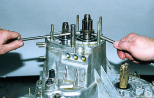
37. Using a large screwdriver, carefully separate the clutch housing and the lada satellite.
There are three places between the crankcases where you can insert a screwdriver to avoid damaging the gasket. Insert a screwdriver into these slots one by one and gently wiggle until the crankcases separate.
38. Remove the transmission case.
39. Remove the bolt securing the 1st and 2nd shift forks.
40. Lift the rod and remove it together with the shift forks for 1st and 2nd gears.
41. Remove the 3rd and 4th shift fork mounting bolt.
42. Disengage the stem head from the lever.
43. ... and remove it together with the plug.
44. Turn the 5th gear fork rod of the VAZ 2108, removing its head from the lever. Remove the stem.
45. Remove the retaining ring.
46. Remove the reverse gear fork.
47. Remove the reverse gear with the axle.
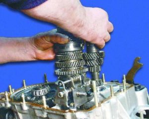
48. Slightly shaking, remove the input and output shafts at the same time.
When both gearbox shafts are removed, the inner rings of the front bearings remain on the shafts.
49. Take out the driven gear wheel of the final drive together with the differential.
50. Remove the three bolts securing the gearshift mechanism.
51. Remove the gearshift mechanism.
52. Carefully remove the gasket.
Do not damage the gasket when removing. An undamaged gasket can be reused when assembling the gearbox.
53. Press the pinion shaft front bearing out of the clutch housing. To do this, you can use the puller foot or similar tool.
Press out the front input shaft bearings and the oil seal only when replacing them or replacing the clutch housing.
54. Press out the oil seal to replace the input shaft front bearing.
It is impossible to press out the input shaft oil seal without damaging it. Therefore, when replacing the input shaft bearing, you will need a new oil seal.
55. Press the bearing into the crankcase by applying force to the outer ring of the bearing.
56. Remove the magnet from the clutch housing.
57. Unscrew the nut that secures the speedometer drive housing.
58. Hook up the housing with a screwdriver.
59. ... and remove the housing from the driven gear of the speedometer drive.
If, during operation, traces of oil leakage through the hole for the speedometer drive were noticed, replace the rubber O-ring on the drive housing.
60. Remove the driven gear with the speedometer drive shaft from the housing.
61. Push the O-ring out of the speedometer drive housing.
62. Unscrew the reverse light switch from the gearbox housing.
63. Slide the protective cover for the shift link joint from the flange on the transmission.
64. Remove the opposite edge of the protective boot from the hinge flange.
65. Remove the bolt securing the hinge to the stem.
66. ... and remove the joint from the stem.
67... Remove the protective cover from the stem.
68. Remove the bolt securing the lever to the shift rod inside the clutch housing.
69. Remove the lever and rod from the clutch housing.
70. If, during operation, traces of oil leakage were noticed through the hole in the clutch housing under the gear shift rod, replace the rod oil seal.
Repair of the VAZ-2109 gearbox includes the following steps:
1. Remove the checkpoint from the VAZ-2109. We clean it from dirt using diesel fuel and a rag.
2. We take out the oil level dipstick from the gearbox.
3. Install the gearbox clutch housing vertically by unscrewing bolts 1 and 2 nuts 3 for fastening the clutch cable bracket. Remove the clutch cable bracket 2 from the gearbox.
4. Unscrew the remaining 4 nuts securing the back cover.
6. Unscrew the 5th gear fork mounting bolt.
7. Fix the gearbox shafts from turning.
8. Unscrew the input shaft securing nut.
9. Unscrew the secondary shaft securing nut.
10. Remove the 5th gear gear together with the synchronizer and the fork from the secondary shaft.
11. Remove the thrust plate from the synchronizer and remove the fork from the groove of the coupling.
12. Remove the 5th gear from the synchronizer with ring 1.
13. Remove the bushing from the secondary shaft.
14. Remove the 5th gear from the input shaft.
15. Unscrew the four screws using an impact screwdriver and remove the thrust washer 2 from the output shaft.
16. Remove the retaining rings of the shaft bearings.
17. Unscrew the 3 retainer plugs and carefully remove the retainer balls.
18. Unscrew the reverse lock plug, remove the O-ring and remove the retainer spring.
19. Remove the retainer ball by tilting the box.
20. Unscrew the 12 nuts and the gearbox housing securing bolt.
21. Separate the gearbox housing from the clutch housing by inserting a screwdriver into the grooves
22. Remove the gearbox housing from the clutch housing.
23. Unscrew the bolts of the gear shift forks 1-2 and 3-4.
24.Lift the 1st-2nd gear shift rod, it will come out of support 3, then turn counterclockwise, its head 1 will come out of engagement with the locking bracket.
25. Turn the shift rod of the 3-4th gear and remove the rod with the fork.
26. We turn the 5th gear inclusion rod and remove the rod.
27. We take out the axis of the reverse gear.
28. Shift the reverse gear until it stops in the gear mechanism, turn it by 30–40 degrees and remove the intermediate gear.
29. We take out the primary and secondary shafts.
30. We take out the differential from the clutch housing.
31. We unscrew the 3 bolts of the gear mechanism and remove the gear mechanism.
32. Remove the magnet from the clutch housing.
33. Unscrew the fastening nut and remove the housing from the speedometer drive gear.
34. Unscrew the reverse switch from the gearbox housing.
35. Press out the secondary shaft bearing.
37. Press out the input shaft bearing.
38. Press the new front shaft bearings into the clutch housing.
39. We move the edge of the protective cover of the stem.
40. We unscrew the bolt of the gear lever, remove the lever and take out the gear rod.
41. Replace the torn protective cover of the stem hinge.
42. To replace the clutch, press out the oil seals.
43. Remove minor damage with sanding paper on the clutch housing and gearbox or replace.
44. Checking the bearing seats in the clutch housing and gearbox. If there is wear, then we replace the crankcases.
45. We check the roller bearings, replace them if damaged.
46. We check the gear shift rods; if damaged, we replace them.
47. We check the seals of the axle shafts, if there is a defect, we replace the seals.
48. We check the input shaft oil seal and the rod oil seal in the gears, in case of defects we replace it.
49. We clean the magnet from the wear particles of the elements. If there is damage, replace the magnet.
50. We clean the clutch and gearbox housings from the old sealant. Putting the checkpoint in the reverse order.
51. Install the shafts in the clutch housing.
52. Liberally lubricate all rubbing elements with oil.
54. Do not forget to replace the magnet.
55. Before installing the gearbox housing on the clutch housing, apply sealant to them around the entire perimeter.
You can read more about clutch operation here.
We install the engine on the car and rejoice at the good dynamic characteristics after the repair of the VAZ-2109 gearbox.
We clean it from dirt and rinse the gearbox from the outside.
In the same way, remove the circlip from the secondary shaft bearing.
You can replace the hinge of the gear selector shaft on the gearbox installed on the vehicle. For clarity, we carry out this operation on the removed stock.
In the same way, we replace the outer ring of the input shaft bearing.
In the same way, we knock out the oil seal and the outer ring of the differential bearing from the gearbox housing. We take out the adjusting ring.
We clamp the input shaft in a vice with soft metal pads.
To disassemble the output shaft, we support the main gear drive gear on a wooden stand.
We insert a chisel or a powerful screwdriver into the gap between the end of the drive gear and the inner ring of the front bearing.
We clamp the secondary shaft in a vice with soft metal pads.
We clamp the driven gear of the final drive in a vice with soft jaws.
To remove the differential bearings, we clamp the box in a vice.
At the service station, car diagnostics are carried out using professional equipment, this procedure costs a lot of money. Therefore, drivers just need to learn how to conduct an independent inspection, it will allow you to understand what is the cause of the VAZ-2109 malfunctions, and will save you money.
How does the gearbox malfunction manifest:
- When stopping, periodically look under the vehicle for oil leaks. If a leak is present, it may be necessary to replace the oil seal located in the transmission.
- Watch for changes in the oil level in the VAZ-2109 engine. Experts say that checking the oil volume should be carried out at least annually, or more often, especially if the machine is actively used. Focus on checking the oil every 20,000 km.
- When changing gears, pay attention to the smooth movement of the shift lever. If jerks and jams occur, then it's time to think about repairing the gearbox in the VAZ-2109.
There can be many reasons for the appearance of a gearbox malfunction in the VAZ-2109. First, decide what are the signs of the breakdown. If difficulties arise when switching speeds, malfunctions may be as follows:
- Not enough or too little lubricant mixture.
- Seized shift shaft.
- The integrity of the gearbox gears is broken.
- A foreign object has accidentally fallen into the gearbox.
- A part called a synchronizer slider was worn out and cannot be repaired anymore.
If a gear is knocked out while the vehicle is in motion or the gear lever returns to neutral, the reasons are indicated in the following list:
- The defect indicates a marriage during the production of a VAZ-2109 unit. That is why, when buying a car, you need to carefully monitor the correct operation of all devices, do not hesitate to ask the seller tricky questions, in the end, you pay. Car warranty repair also does not mean that the part will eventually be repaired.
- The teeth of the gears are worn out, then the ring with the teeth becomes like a cone and the destruction of the fixation of the gears becomes obvious.
- If the condition of the VAZ-2109 gearbox shaft, gears or bearings leaves much to be desired, then the bearing leaves its intended place or shifts slightly to the side.
Car enthusiasts on the forums dedicated to the maintenance and repair of the VAZ-2109 indicate additional defects and malfunctions of the auto gearbox:
- Noises appear, indicating wear of bearings and gears, the result of such a malfunction may be the lack of adequate adhesion of the components. The damage most likely affected the synchronizer or the box structure. Knocking may be added to the noise. Driving such a car is dangerous for the health and life of the driver and passengers.
- If you notice oily stains under the vehicle, it should be assumed that the transmission is leaking. Why does this malfunction occur? If the crankcase cover is loose or it is time to replace the stuffing box shaft. You can fix the problems with your own hands, without resorting to the expensive services of service station specialists.
- Overheating of the gearbox is another unpleasant factor, which means that too little oil has been filled.
VAZ-2109 maintenance and repair of the gearbox sooner or later have to be done by every owner of a domestic car.
- 2 types of hammers, one of which is made of rubber and the other is normal;
- screwdrivers with different tips;
- mark;
- set of cap heads;
- impact screwdriver;
- wrench to help remove retainer rings.
During the repair of the checkpoint in the VAZ-2109, you may encounter the problem of sticking of some components, you still continue to follow the step-by-step instructions, and the desired result will not take long to arrive:
- In what condition the bearings are, if they are badly worn out, this will lead to the appearance of a hum.
- Inspect the synchronizer and the material sealing washer - wear causes poor gear shifting.
- Rings and synchronizers with notches and deep chips require replacement.
- Measure the gap between the gears and the locking rings, ideally it should not exceed 0.6 mm.
When the parts that were completely worn out are replaced with new ones, it remains to assemble the gearbox. But before that, thoroughly rinse all parts and remember the following requirements:
- Before laying the gaskets, apply an even layer of lithol on them. The substance guarantees the displacement of the gaskets during assembly.
- When starting to press in the oil seals, focus on the working edge from the inside, at this time the metal cage should be placed outside.
There is a special offer on our website. You can get a free consultation of our corporate lawyer by simply asking your question in the form below.
Assemble the gearbox in the reverse order of disassembly. When doing this, keep the following in mind:
- before attaching the thrust hinge and the lever to the gear selector rod, degrease the threaded holes in the hinge housing and in the lever hub, as well as the mounting screws, apply special TB-1324 glue to the screw threads and tighten them;
Lever and pivot screws have different lengths, plating and tightening torques. The lever fastening screw is phosphated (dark) with a length of 19.5 mm, its tightening torque is 33.6 Nm (3.4 kgf 19.1 N m (1.95 kgf m).
- along the outer diameter, the primary shaft oil seal, the wheel drive oil seals and the gear selector shaft oil seal housing, install on the KLT-75TM or TV-1215 liquid gasket;
- before installing the oil seals of the input shaft and the gear selection rod, as well as the clutch release fork shaft, lubricate the working surface of the oil seals with a thin layer of Litol-24 grease and the SHRUS-4 grease of the clutch release fork shaft sleeve;
- after installing the selector rod in the clutch housing, check that the flange of the hinge tip goes inside the groove of the cover along the entire perimeter;
- put LSC-15 grease in the ball joint of the gear shift lever;
- tighten the fasteners with the torques specified in Appendix I;
- Assemble the secondary shaft in the reverse order of disassembly, with the synchronizers installed on the shaft in the assembled state, with a mandrel A.70152, preheating them to a temperature of 100 ° C and replacing the locking rings of the synchronizer couplings with new ones.
When the heated parts cool, the locking rings on the gear cones may jam. To eliminate this, before installing the heated synchronizer on the shaft, install a special fork-shaped gasket between the locking rings and the ends of the gears, which should be removed after the parts have cooled.
When assembling the synchronizer, install the locking rings so that the protrusions A (Fig. 3.26) of a lower height, and not a greater one, are located opposite the hubs for the springs of the retainers, otherwise the gears will not change after assembly.
To facilitate the installation of the retainer, apply a little grease to its ball, put it in the cracker and, pressing the spring with a screwdriver towards its socket, reinstall the cracker assembly with the ball. In this case, the seat (deepest) in the sliding sleeve must be located opposite the ball.
Rice. 3.24. Output shaft prepared for assembly
Rice. 3.25. Installation of the driven gear wheel of the 1st transfer
Rice. 3.26. Installation of the synchronizer for 1st and 2nd gears and the driven gear of 2nd gear
The assembly operations of the output shaft are shown in fig. 3.24, 3.25,3.26, 3.27.
Rice. 3.27. Installation of a synchronizer for III and IV gears and a driven gear wheel for III and IV gears
Rice. 3.20. Details of the secondary shaft: 1 - nut; 2 - ball bearing; 3 - thrust washer; 4 - bearing sleeve; 5 - needle bearing; 6 - gear wheel of IV transfer; 7 - distance bearing ring; 8 - blocking ring of the synchronizer; 9 - sliding sleeve for synchronizer of III and IV gears; 10 - sliding clutch hub; 11 - gear wheel of III transfer; 12 - retaining ring; 13 - persistent half rings of the secondary shaft; 14- gear wheel of II transfer; 15 - sliding clutch for synchronizer of 1st and 2nd gears with reverse gear; 16 - locking ring of the synchronizer hub; 17 - hub of the sliding clutch of the synchronizer for 1st and 2nd gears; 18 - synchronizer spring; 19 - biscuit; 20 - retainer; 21 - gear wheel of 1st transfer; 22 - roller bearing; 23 * - thrust washer; 24 * - bearing sleeve; 25 * - gear wheel of V transfer; 26 * - sliding clutch hub; 27 * - sliding sleeve of the V gear synchronizer; 28 * - thrust plate
* Five-speed gearbox parts
Since 1989, the thrust washer 3 (see Fig. 3.20) on the secondary shaft has been canceled and the configuration of the secondary shaft and pinion 21 of the first gear has been changed (the ring gear on the secondary shaft has become wider by the thickness of the washer 3, and the grooves have been canceled at the end of pinion 21). The specified parts are not interchangeable with previously produced ones. Therefore, when repairing old gearboxes, observe the following rules:
- if the washer 3 changes, then the output shaft and the gear wheel of the 1st gear are set to the "old" design;
- if instead of gear 21 or the secondary shaft, parts of the same name of a new design are installed, then they must be changed completely, that is, when the gear 21 is replaced, the secondary shaft also changes and vice versa. In this case, the washer 3 is not installed.
Assemble the differential in the reverse order to disassembly, having previously lubricated the side gears and satellites with engine oil. The axial clearance of the semiaxis gear should be no more than 0.4 mm, and the torque of resistance to rotation of the differential gears should not exceed 10.0 N m (1.0 kgf m). If the clearance is increased, which is a sign of wear on the differential parts, replace the worn parts with new ones.
Using a mandrel 67.7853.9565, press the inner rings of the bearings onto the differential box, having previously installed the drive gear of the speedometer drive.
Having installed the clutch housing on the stand for assembling the gearbox, press the stem oil seal into the socket with a mandrel 67.7853.9563, and then insert the gear selection rod into the hole of the crankcase and fix the gear selection lever on it, having previously degreased the threaded hole and the screw and applied special glue to the screw thread TB-1324.
Rice. 3.28. Pressing in the secondary shaft bearing: 1 - mandrel 67.7853.9574
With a mandrel 67.7853.9574, press the outer rings of the roller bearings of the primary and secondary shafts together with cages (Fig. 3.28) into the clutch housing, and press the inner rings of these bearings onto the shafts. Press in the outer rings of the differential bearings with a mandrel 67.7853.9575.
Install the gear selector, making sure that the gear selector lever is in the correct position relative to the gear selector lever. Secure the gear selector.
Press the oil seal into the clutch housing, keeping the dimension (3.5 ± 0.2) mm (see Fig. 3.7) so that the working edge of the oil seal is located on the polished belt of the shaft.
Press ball bearings onto the input and output shafts, screw on the nuts and tighten them with a torque wrench, then stamp the nuts. The caulk length should be 3.5–4 mm and should not overlap with the shaft thread. Secure input shaft with special tool 41.7816.4070 when tightening nuts on shafts.
Install the differential in the crankcase. To prevent the side gears from moving out of their seats during assembly, fix one of them on the side of the clutch housing with a technological mandrel or a plug used when transporting the gearbox.
Rice. 3.29. Installing gear shift rods and forks
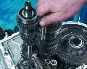
Install the input and output shafts together with gears at the same time. Then install the axle with the reverse gear, while making sure that the reverse fork goes into the groove of the intermediate gear. Then install the gear shift rods and fix the forks on the rods (Fig. 3.29).
Install a cleaned magnet into the crankcase seat.
Install a gasket between the clutch housing and the transmission housing.
Select the shim for the differential bearings as shown below (see "Selecting the Shim for Differential Bearings").
Install the selected adjusting ring into the gearbox housing seat and press the outer ring of the differential tapered roller bearing with the mandrel 67.7853.9575.
Reinstall the speedometer drive.
Install the transmission housing to the clutch housing and secure it with nuts. Install the locating rings in the grooves of the bearings of the input and output shafts.
Reinstall the rod and reverse fork retainers, secure the retainer cover and tighten the reverse fork retainer plug.
Determine the thickness of the adjusting ring with special tool 67.7824.9517 in the following sequence:
Rice. 3.30. Diagram for selecting the thickness of the adjusting ring of the differential bearings: 1 - indicator, 2 - support mandrel, 3 - differential bearing, 4 - adjusting ring, 5 - mandrel
- press the outer ring of the tapered roller bearing 3 together with the locating ring 4 (Fig. 3.30) into the gearbox housing;
The adjusting ring 4 has a constant thickness of 1.25 mm.
- Press the outer ring of the other differential bearing into the clutch housing. At the same time, make sure not to confuse the outer rings of the differential bearings;
- install the differential in the gearbox housing and, closing it with the clutch housing, tighten at least three nuts, equidistant from each other, securing the gearbox housing to the clutch housing (tightening torque 24.5 N · m (2.5 kgf · m). Then turn the differential for self-aligning bearings by 2-3 turns;
- install support mandrel 2 on the differential box and fix indicator 1 with an extension using a universal holder. Install the indicator leg on the support frame with a preload of 1 mm, and fix the indicator in this position, and set the arrow to zero;
- move the differential from below and watch the indicator reading;
When measuring the axial displacement of the differential, do not turn it so as not to distort the measurement results.
Using the formula S = A + B + C, calculate the thickness of the adjusting ring of the differential bearings, where
S is the thickness of the adjusting ring;
A - the value of the axial movement of the differential;
B - the value of the preload of the differential bearings;
C is the thickness of the adjusting ring (constant value).
Example. The indicator reading when moving the differential is 1.00 mm. The value of the preload of the differential bearings is 0.25 mm, the thickness of the adjusting ring is 1.25 mm:
After determining the thickness of the adjusting ring, separate the clutch housing and the gearbox, remove the differential, press out the outer bearing ring from the gearbox housing with a puller 67.7801.9526 and replace the adjusting ring 4 with the selected adjusting ring. Press in with a mandrel 67.7853.9575 the outer ring of the differential bearing and install the differential in the gearbox housing and, closing it with the clutch housing, tighten the nuts securing the gearbox to the clutch housing.
Check the torque of the differential turning with a dynamometer 02.7812.9501. To do this, pass the dynamometer tip through the hole in the differential box (for the wheel drive shaft) until it covers the axis of the satellites. Turn the handle of the dynamometer a few turns clockwise and read the moment of resistance to turning on the scale. It should be: for new bearings 147–343 N · cm (15–35 kgf · cm), for worn-in bearings at least 30 N · cm (3 kgf · cm).
Do-it-yourself repair of a VAZ 2108 gearbox depends on which device is in the car - for 5 or 4 gears.From a design point of view, this part is connected to the differential, the final drive. It is better to purchase a gearbox repair kit so that all the tools and materials are at hand.
All elements of the four-speed gearbox VAZ 2108:
Through the drive 41 and 5, located on the front wheels, from this product, the torque is transmitted to the drive wheels. Disassembly of the gearbox is carried out in different ways, depending on the device of the part.
For example, the main malfunctions of the four-stage option may involve working with the following parts:
- Drive design that assists in gear shifting.
- Differential.
- The most important transmission detail.
- The reverse gear has its own idler gear, it is located on a separate axle.
- Two synchronizers.
- No design is complete without a secondary and primary shafts.
- Carter 1.
For the manufacture of the crankcase, an aluminum-based alloy is always used. This must also be taken into account if the elimination of gearbox noise is required. The back cover helps to hide everything. A breather is pressed into its socket. Bearing seats are made at the rear. There are also two holes that are closed with plugs. The secrets of repair are to work correctly with each of the elements.
The input shaft is located in the crankcase and is mounted on two bearings. This shaft itself is made in the form of gears and reverse gears, a block of gears.
Replacing the gearbox bearing requires interaction with such devices.
Reverse speed repair must take into account that the secondary shaft and the pinion on the final drive form a single composition. In the space between the roller and ball bearings, it rotates. The gears responsible for 4.3, 2 and 1 gear can be found on the output shaft belts, on needle-type bearings. A detailed repair manual will also say that the splines on which the hubs are attached to 12 synchronizers are cut using 2 small belts.
All elements of the output shaft:
1 - nut; 2 - ball bearing; 3 - thrust washer; 4 - bearing sleeve; 5 - needle bearing; 6 - gear wheel of IV transfer; 7 - distance bearing ring; 8 - blocking ring of the synchronizer; 9 - sliding sleeve for synchronizer of III and IV gears; 10 - sliding clutch hub; 11 - gear wheel of III transfer; 12 - retaining ring; 13 - persistent half rings of the secondary shaft; 14 - gear wheel of II transfer; 15 - sliding clutch for synchronizer of 1st and 2nd gears with reverse gear; 16 - locking ring of the synchronizer hub; 17 - hub of the sliding clutch of the synchronizer for 1st and 2nd gears; 18 - synchronizer spring; 19 - biscuit; 20 - retainer; 21 - gear wheel of 1st transfer; 22 - roller bearing; 23 * - thrust washer; 24 * - bearing sleeve; 25 * - gear wheel of V transfer; 26 * - sliding clutch hub; 27 * - sliding sleeve of the V gear synchronizer; 28 * - thrust plate.
From 23 to 28, the details of the VAZ 2108 five-speed gearbox are marked.
Each of the gears must have two teeth:
The bevel-toothed rim structures provide permanent engagement for the gears on the input shaft. When the gear is engaged, there is a connection of the synchro-clutches with the rims, which have straight teeth. This is also part of the design of the gear selection mechanism at the checkpoint.
The backstage renovation touches on other details. The gears are silently switched to each other precisely due to the work of the synchronizer. On the input and output shafts, the angular speeds for the gears are constantly aligned to achieve the desired result. The primary and secondary shafts themselves contain several elements. Each gearbox repair scheme contains references to them.
- Each gear has a ring gear.
- The retainer works on springs.
- Rusks with balls in the amount of three.
- Two Rings responsible for blocking.
- Part of a clutch that can slide.
- Hub mounted on the splines of the output shaft.
Where to repair the gearbox? You can do it in your own garage - this is a fairly simple job. Different gears may have different types of synchronizers, but they are not very different from each other.
The process of installing the driven gear of the first gear.
After studying the device, car owners are wondering how to remove the checkpoint on a VAZ 2108. Installation and dismantling of the checkpoint should not cause difficulties if you follow the points.
Details of the disassembled gearbox from the VAZ 2108.
Maintenance of the gearbox involves carrying out work related to the removal, which are carried out in the lower part of the car.
Before overhauling the VAZ gearbox, it is necessary to completely clean the parts inside. A brush or scraper must be used to remove all deposits. A strong jet of air is suitable for flushing and blowing. The clearances of the gearbox gear are also completely cleaned.
Gearbox transmission repair is not as difficult as it might seem. And checkpoint breakdowns are not as bad as you might think at first glance. It is enough to carefully study the checkpoint repair manual in order to perform all the necessary work at home.

