1. Flush the transmission and install it on the bench. Drain the oil and remove the bottom cover with gasket.
23. Disassemble the input shaft (see fig. Details of the input shaft):
- remove the circlip 7, the blocking ring 6 and the spring 5 of the synchronizer;
26. Remove the protective cover 10, lock and thrust rings 6 and 7, spring 5 and spherical washer 4 from the gear shift lever (see Fig. Details of the lever and gear selection mechanism).
1. Assemble the gearbox in the reverse order of disassembly.
8. When installing the clutch housing with the front cover of the gearbox, the hole in the front cover should be located as shown in fig. from item 3.
To facilitate the removal and subsequent installation of the elastic coupling, we wrap it tightly with tape.
Remove the flexible coupling flange, gearbox support, speedometer drive (see Gearbox replacement).
Using the "10" key, unscrew the three nuts securing the ball joint of the gear lever and.
... remove the lever from the studs of the rear cover of the gearbox.
Using the "27" key, turn off the reversing light switch and.
Remove the lower gearbox cover (see. Gearbox repair) and.
... using the "13" wrench, unscrew the nut securing the rear cover to the gearbox housing.
We unscrew the remaining nuts securing the rear cover to the gearbox housing (see.Gearbox repair).
With a screwdriver, we recessed the reverse gear and V gear.
Remove the rear transmission cover.
We remove the rear bearing of the secondary shaft and.
We remove the drive gear of the speedometer drive with a retainer - a metal ball and.
Using the "10" key, unscrew the bolt securing the forks of the 1st and 2nd gears.
Use a screwdriver to turn on the 2nd gear.
Using the "17" head, unscrew the bolt securing the gear block.
Remove the gear block mounting bolt.
We take out the block of gears of the V gear and reverse.
Remove the spacer washer.
Using the "13" wrench, unscrew the two bolts securing the retainer cover and removing it.
… We take out three springs and three balls of retainers.
Remove the 5th gear bushing.
Remove the V gear assembly with a synchronizer.
Raising the stem, remove the V gear synchronizer sleeve and.
... reverse idler gear.
We remove the rod of inclusion of the 5th gear and reverse gear with a fork.
Remove the V-gear synchronizer clutch hub.
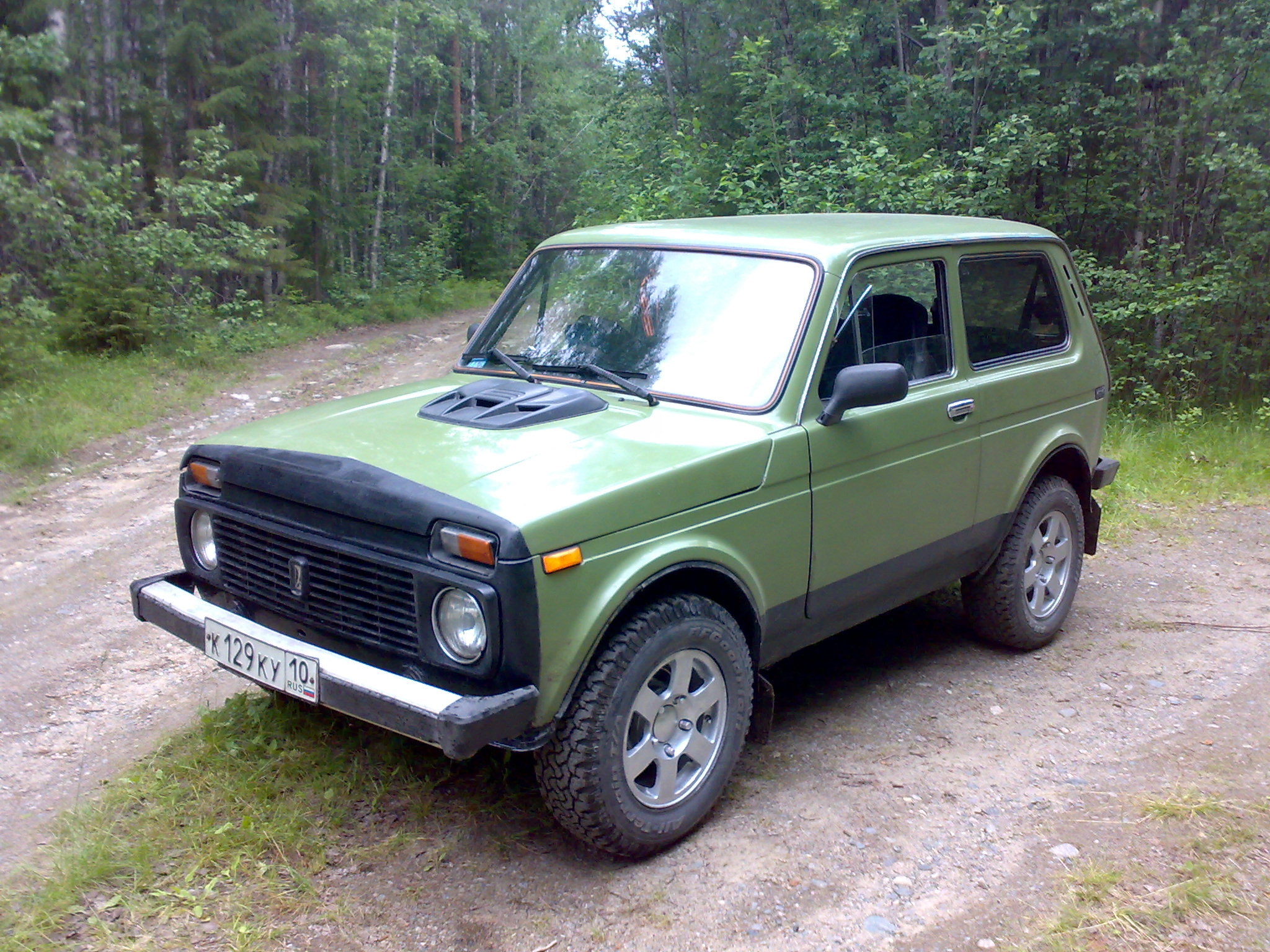
The Niva car is positioned as an off-road vehicle with increased cross-country ability. Due to this, there is a demand for the car. A solid load-bearing body is installed. The Niva 2131 is based on the LADA 4 × 4. Its tuning allows you to change the exterior, performance for the better. Since the mid-1990s. injection engines became available for Niva machines.
In addition to passenger cars, self-propelled vehicles are also produced under the Niva brand. In particular, this is Niva SK 5. This car is a combine intended for harvesting crops. The machine runs on diesel fuel.
A VAZ 21213 car with an engine volume of 1.7 liters. can develop power up to 79 horsepower. Fuel consumption averages 10 liters per 100 km. As is typical for gasoline engines, there is a central injection system. Such vehicles should be refueled with AI-95 gasoline.
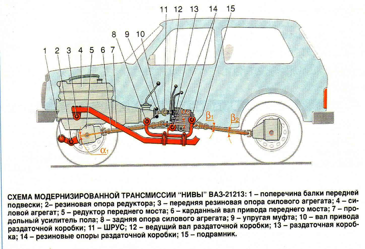
The Niva checkpoint (VAZ 21213) is mechanical, five-speed. The Niva transmission has a permanent four-wheel drive. It should be noted the presence of a reliable gearshift lever extension on the Niva. Thanks to him, the speed changes are quickly carried out. The existing camshaft drive is a chain drive. The crankshaft includes several connecting rod and main journals. The crankshaft is durable, made of cast iron. The timing mechanism is closed with a lid. There is an oil filler neck here.
A transfer case is installed on the Niva 2121. Its peculiarity is that it has both an overdrive and a downshift. Increased is important to use if you need to save on fuel consumption. In the event that the movement takes place over rough terrain, a lower gear helps out. However, in this case, fuel consumption will increase.
The razdatka allows, if necessary, to disable one of the driving axles. The transfer case includes shafts, differential, gearshift clutch. The main breakdowns are expressed in the fact that its main components wear out over time, as a result of which, overheating of the box may be noted, problems with switching on the bridge may appear. Repair of the VAZ 21213 gearbox is required if characteristic vibration from this unit began to be noted.
Thus, the popularity of the car is due to the fact that it has an all-wheel drive system. The speed box diagram shows that it contains a large number of component parts that interact with each other, ensuring excellent vehicle performance.
To carry out a full-fledged diagnosis, the high-speed box must be removed. As a rule, there is a need for this if vibrations, extraneous noise, oil leakage increase during movement.
How to remove the box? Before you start removing the gearbox, you must remove the transfer case. Without an inspection hole, it will be difficult to carry out repair work, for example, unscrew the cardan shafts from the distributor. The stabilizer is also removable.Removable air filter housing.
In order to remove the gearbox, disconnect the lever rod, clutch housing cover fasteners, propeller shaft, bolts, nuts, remove the bracket. The suspension of the power unit is adjacent to the body. To remove it, you must unscrew the fastening nuts.
To extend the working life of the VAZ 21213 gearbox, it is advisable to periodically check the level of the transmission fluid and change it in a timely manner.
It should be noted that quite often the appearance of extraneous noise from the side of the gearbox is a consequence of the fact that there is a reduced level of transmission oil in the system.
Mineral oil can be added to the machine. However, semi-synthetic and synthetic options have the best performance. The advantage of the latest types of oils is that the gears will be easily switched on even in winter.
VIDEO
Timely maintenance of the Niva box allows you to avoid a complete bulkhead of the checkpoint. Assembling all dismantled parts is a painstaking task and should be trusted by professionals. Replacing the gearbox input shaft bearing is a frequent procedure that is ordered from a service center.
We drain the oil from the gearbox, remove the fork and the clutch release bearing (see the relevant sections).
Dismantle the flange of the elastic coupling from the toe of the secondary shaft (see. Replacing the secondary shaft oil seal) ...
The gear selection mechanism can be removed from the vehicle without removing the gearbox. For clarity, these operations are performed on the removed gearbox.
Remove the gear selector cuff.
Set the gear lever to neutral.
Using the "10" head, unscrew the three nuts securing the gear lever housing ...
… And take out the gear selection mechanism.
The connection is sealed with a gasket.
With a marker, we mark the relative position of the washers and the guide plate of the mechanism.
Using the "10" head, unscrew the two nuts securing the reverse locking plate, holding the bolts with a wrench of the same dimension, ...
... and remove the blocking plate.
… Remove the bottom washer of the guide plate.
Taking out one guide bar with two springs, ...
… Remove the guide plate from the lower end of the arm.
Remove the top washer of the guide plate.
Remove the gear lever housing.
We take out the rubber sealing rings of the bolts from the grooves of the body.
Remove the bottom gasket of the ball joint housing.
Removing the flange with a protective cover ...
... and the upper body gasket.
Remove the retaining ring with pliers.
Removing the spherical washer ...
… And disconnect the lever and the ball joint housing.
We install the gearbox with the clutch housing on the workbench.
Using the "10" head, unscrew ten nuts securing the lower gearbox cover.
... and a gasket.
Using a screwdriver, through the hole of the gear selection mechanism, move down the plug of the I – II gear engagement fork (in this case, the II gear is engaged).
Using the "13" key, unscrew the rear cover fastening nut located inside the box body.
Using the "13" wrench, unscrew the five nuts securing the back cover located outside the case.
We tap with a hammer on the cover lugs, while using a screwdriver (or a suitable piece of pipe with the output shaft seal removed) we hold the rear bearing on the output shaft.
We move the cover off the studs and remove it by turning it clockwise (looking from the side of the secondary shaft shank) in order to prevent the cover from catching on the rods and the gear block of the 5th gear and reverse.
To replace the bearing of the V gear and reverse gear block ...
… Pry on the bearing rollers with a screwdriver.
... and remove the rollers from the separator.
Prying the outer ring of the bearing with a hook, ...
... take it out of the back cover slot.
Remove the thrust washer of the secondary shaft rear bearing.
Remove the outer bearing ring with a cage and rollers.
Remove the inner bearing ring.
... and a slinger washer.
To lock the shafts from turning, it is necessary to engage two gears.2nd gear was engaged when the rear cover was removed. Before engaging reverse or V gears, release the plug for engaging these gears. For this…
… With a “10” key, unscrew the bolt securing the fork to the rod.
Pressing the fork down with a screwdriver, turn on the reverse gear.
With a spanner wrench (head) "17" we unscrew the bolt securing the gear block for the V gear and reverse.
... and remove the gear block from the countershaft splines.
Clamp the V gear and reverse gear block in a vice with soft metal jaw pads.
With two screwdrivers we press the inner ring of the bearing of the gear block ...
... and remove the inner ring.
We remove the sleeve of the gear wheel of the V transfer, ...
... the gear itself with the synchronizer blocking ring.
Turning the fork for engaging the V gear and reverse gear on the rod to the secondary shaft, ...
… Remove the reverse gear.
Using a spanner wrench "13", unscrew the two bolts securing the retainer cover.
Remove the cover and gasket.
We take out the springs of the clamps (the spring of the V gear and reverse rod is longer than the other two and has a dark coating color).
With a magnetized screwdriver, remove all three clips.
We take out the V gear and reverse gear with a fork.
With a magnetized screwdriver, remove the blocking cracker from the hole in the gearbox housing, which is located between the sockets of the crankcase for the rods of the 5th gear and reverse gears and III-IV gears.
We remove the driven gear wheel of the reverse gear from the secondary shaft.
We take out the key from the groove of the shaft.
Using the “10” head, unscrew the bolt fastening to the rod of the 3rd-4th gear shift fork.
A blocking cracker is inserted into the stem hole, ...
With a magnetized screwdriver, remove the blocking cracker from the hole in the gearbox housing, which is located between the crankcase sockets for the rods of I – II and III and IV gears (this cracker is noticeably longer than the cracker located between the 5th gear - reverse gear and the III – IV gears) ...
Using the "10" head, unscrew the bolt fastening to the rod of the I-II gear shift fork.
Using an impact screwdriver with a Phillips tip, unscrew the three screws securing the retaining plate of the intermediate bearing of the secondary shaft.
The screws are locked with special washers.
Remove the locking plate.
Using a 19 spanner wrench, unscrew the nut securing the axle of the intermediate reverse gear, keeping the axle from turning with the “24” wrench.
We take out the axis of the intermediate reverse gear.
Having unscrewed the nuts securing the clutch housing (see Replacing the input shaft oil seal).
… Separating the clutch housing and gearbox.
We remove from the input shaft a spring washer with a tapered surface (with a smaller diameter it faces the bearing).
We clamp the spline part of the input shaft in a vice with soft metal jaws.
With a spanner wrench "19", unscrew the bolt of the clamping washer of the front bearing of the intermediate shaft.
Remove the bearing clamp washer.
With two screwdrivers we pry the front double-row bearing of the intermediate shaft by the locating ring ...
When the bearing is removed, its rear inner ring may remain on the shaft.
Press the inner inner ring of the bearing with two screwdrivers ...
We take out the thrust ring of the rear bearing of the intermediate shaft.
By inserting a screwdriver between the ends of the bearing and the gears of the 1st gear of the intermediate shaft, we shift the rear bearing.
We take out the outer bearing ring with a cage and rollers.
Remove the inner bearing ring from the shaft nose.
By sliding the intermediate shaft back, ...
… Take it out of the gearbox housing.
Prying the rear bearing of the input shaft with two screwdrivers on the locating ring, ...
… Take out the input shaft complete with bearing and synchronizer blocking ring.
Use pliers to open the retaining ring ...
We support the end of the outer ring of the bearing on the vise jaws.
With a hammer with a plastic striker, we strike at the end of the input shaft ...
... and press the bearing.
Use pliers to open the adjusting ring ...
Having moved the blocking ring of the synchronizer, we unclench the blocking ring with pliers ...
Removing the locking ring ...
The blocking rings of synchronizers of other gears are removed in the same way.
Remove the needle bearing from the front toe of the output shaft.
We remove the forks of inclusion of I and II, III and IV gears.
With two screwdrivers we pry the intermediate shaft bearing by the locating ring ...
Having tilted, we remove the secondary shaft complete with gears, couplings, hubs and synchronizer blocking rings from the gearbox housing.
Remove the bushing and the 1st gear gear assembly with the locking ring from the rear side of the shaft.
We take out the bushing from the gear.
Remove the synchronizer sleeve for engaging 1st and 2nd gears.
Remove the synchronizer hub.
Remove the 2nd gear gear assembly with a locking ring.
From the front end of the secondary shaft, remove the synchronizer sleeve for III and IV gears.
Clamping the secondary shaft in a vice with soft metal jaw pads, ...
… Remove the retaining ring with pliers.
Remove the spring washer (it is installed with the convex side to the front end of the shaft).
Remove the synchronizer hub for III and IV gears.
... and a gear wheel of the III transfer assembly with a blocking ring of the synchronizer.
We carry out the assembly of the gearbox in the reverse order.
... use a screwdriver to carefully remove the separator with balls ...
... and put it on the inner ring (removed from the shaft).
Insert the cage with balls and an inner ring into the outer ring of the bearing.
When assembling the input shaft ...
… Press the bearing onto the shaft with a suitable piece of pipe, resting on its inner ring.
After installing the secondary and intermediate shafts in the gearbox housing, we press in the front and rear bearings of the intermediate shaft, the intermediate bearing of the secondary shaft and the inner ring of the bearing of the gear block.
… Press with a tool head of a suitable size (pipe piece) into the socket of the rear cover.
We insert a separator and rollers into the outer ring of the bearing.
Disassembly and repair of the gearbox is required for the following malfunctions.
1. Spontaneous switching off or indistinct switching on of gears:
- wear of holes for balls on rods, breakage of retainer springs;
- wear of the blocking ring of the synchronizer;
- breakage of the synchronizer spring;
- wear of the teeth of the synchronizer clutch or the synchronizer ring gear.
2. Increased noise in the gearbox:
- wear of gear teeth and synchronizers;
3. Difficult gear shifting:
- wear of the spherical hinge of the gear lever, lack of lubrication in the unit;
- deformation of the gear lever;
- burrs, curvatures, contamination of the stem seats, jamming of blocking nuts;
- contamination of the splines of the sliding sleeve and hub;
- deformation of the gear shift forks.
4. Low oil level or oil leak:
- wear of the seals of the primary and secondary shafts;
- loosening of the gearbox housing covers, damage to the gaskets;
- loosening of the fastening of the clutch housing to the gearbox housing.
The listed malfunctions can be caused by other reasons, the elimination of which does not require the removal and disassembly of the gearbox.
You will need: screwdrivers (two), replaceable heads "for 13", "for 17", an extension cord, a knob, keys "for 10", "for 13" (two), "for 17", "for 19", "for 30 ”, impact screwdriver, snap ring puller, hammer, universal pullers.
We drain the oil from the gearbox, remove the fork and the clutch release bearing.
2
The gear selection mechanism can be removed from the vehicle without removing the gearbox. For clarity, these operations are performed on the removed gearbox.
6
For disassembly and assembly of the gearbox gear selection mechanism, see the article - "Disassembly of the gearbox gear selection mechanism".
We will show you how you can repair the gearbox of the gearbox on a NIVA 2131 car with your own hands. This malfunction cannot be fully called Niva's disease, but it occurs quite often. Breakage is always different, depending on the use of the machine. If the NIV is used by its immediate meaning, like an SUV, then mostly the second gear takes off. If the car often walks on the highway, then in most cases it is necessary to repair the 5th gear. If the car drives in the city, sometimes driving out mud, then 4th gear suffers, as in our case. 1st and 3rd gear also fails, but very, very rarely.
The repair is shown in great detail, from convenient angles, you will also learn how to remove the checkpoint, put it back.
Here is such a slurry from the shavings was found on the pallet:
After disassembling the box, all bearings, a coupling, a primary shaft with a bearing, and a needle bearing were sentenced to replacement. The rest is still similar. New oil seals, gaskets are necessarily bought
Video repair of the gearbox (gearbox) on the NIVA 2131:
VIDEO
For those who are interested in how much such repairs cost in auto services, in this particular case, 5500 rubles were paid for removing the checkpoint, bulkhead and reinstallation, we can say that it is cheap. The service is located almost in the countryside, in the city the amount must be multiplied by 2, and this is without taking into account the cost of spare parts.
To facilitate the removal and subsequent installation of the elastic coupling, we wrap it tightly with tape.
Remove the flexible coupling flange, gearbox support, speedometer drive (see Gearbox replacement).
Using the "10" key, unscrew the three nuts securing the ball joint of the gear lever and.
... remove the lever from the studs of the rear cover of the gearbox.
Using the "27" key, turn off the reversing light switch and.
Remove the lower gearbox cover (see. Gearbox repair) and.
... using the "13" wrench, unscrew the nut securing the rear cover to the gearbox housing.
We unscrew the remaining nuts securing the rear cover to the gearbox housing (see Gearbox repair).
With a screwdriver, we recessed the reverse gear and V gear.
Remove the rear transmission cover.
We remove the rear bearing of the secondary shaft and.
We remove the drive gear of the speedometer drive with a retainer - a metal ball and.
Using the "10" key, unscrew the bolt securing the forks of the 1st and 2nd gears.
Use a screwdriver to turn on the 2nd gear.
Using the "17" head, unscrew the bolt securing the gear block.
Remove the gear block mounting bolt.
We take out the block of gears of the V gear and reverse.
Remove the spacer washer.
Using the "13" wrench, unscrew the two bolts securing the retainer cover and removing it.
… We take out three springs and three balls of retainers.
Remove the 5th gear bushing.
Remove the V gear assembly with a synchronizer.
Raising the stem, remove the V gear synchronizer sleeve and.
... reverse idler gear.
We remove the rod of inclusion of the 5th gear and reverse gear with a fork.
Remove the V-gear synchronizer clutch hub.
Permissible sizes of gearbox wearing parts
ALER: I recommend that you look at the comments that I made firesanek (Conversion of the checkpoint into a “torn package”).
During the assembly process, you need to remember about one important operation - turning the shafts after each next installed part. The shafts should rotate easily without pinching. If a tight rotation is felt after installing any part, then this part is defective and must be replaced. Do not be too lazy to do this, otherwise the work will be in vain, the checkpoint will either not work normally, or it will quickly fail again.
Clamp the output shaft in a vice through a rag and make cuts with a grinder on both sides at its rear end to fix the shank nut:
Attention! If the secondary shaft is worn out or defective, it makes sense to make a cuts purchased instead of at the very end of the assembly process, after installing the gearshift mechanism and checking its operation. In the event of a defect due to these cuts, you will not be able to return the purchased shaft to the store.
We lubricate the inner race of the input shaft bearing with oil or lithol. We put the input shaft on a wooden block, put the bearing on it with a groove with a fixing washer upwards. We put it on the shaft through a mandrel (pipe of a suitable diameter):
We put the spring ring and the retaining ring, we set it down with light hammer blows through the chisel until it is completely fixed:
If it is necessary to replace the synchronizers, we remove them, as it was written above about the fifth gear, and change the synchronizers:
In this case, the retaining rings must be turned over due to depletion in the places of contact with the synchronizer. The bent end of the spring must fall into its “own” cavity between the teeth:
If the synchronizer “sticks” or is not pressed parallel to the thrust washer when moving along the axis, the end of the spring is incorrectly positioned.
We collect the secondary shaft. The left photo shows all the parts and assemblies mounted on the output shaft. The order of their arrangement is as follows: the bottom row from left to right, then the middle one is also left to right, then the top one. In the right photo, the same parts and assemblies are installed on the output shaft:
We put the third gear gear and its hub on the secondary shaft. Pay attention to the asymmetry of the hubs. On the one hand, the slots have a cutout (left photo), on the other - not:
The notches on the three splines of the hub should point towards the gear (left - right):
We put on the snap ring and retaining ring in the same way as they put these parts on the input shaft.
We put on the second gear gear and the first-second gear hub:
The notches in the splines of the hub should be directed towards the second gear gear (left - right):
We put on the first-second gear clutch, the first gear assembly, as well as the third-fourth gear clutch. We check the ease of movement of the couplings on all gears:
The secondary shaft with assembled from the first to the third gears is installed in the gearbox housing.
We install the forks of the first-second and third-fourth gears with the holes for the bolts up (remember: the gearbox is clamped in a vice with the pallet facing up).
Install the secondary shaft bearing flange. Before tightening the screws, inspect the castellated washers under their heads for cracks. Tighten the screws with an impact screwdriver using a hammer.
Further, after installing each next part, we turn the primary and secondary shafts several times. They should rotate without jamming.
When installing the rods, we check the ease of their movement in the holes in the crankcase wall: there should be no jamming.
We install the rod of the first or second gear, tighten the fork with a bolt (turn the shafts) and put in a long cracker:
Install the third-fourth gear stem. We do not insert it into the plug completely, orient the hole in the rod under the blocking cracker horizontally and insert the cracker:
We push in the rod and tighten the fork bolt (turn the shafts).Similarly to the first-second gear ratchet, we install a short rusk.
Insert the intermediate shaft: first the rear end, then the front. We put the middle bearing of the intermediate shaft. Note that the inner bearing race consists of two parts: a sleeve and a ring.
Adding by vzhik. The bushing must be oriented so that it is inside the crankcase and the ring is outside. If the roller bearing is incorrectly installed - with the sleeve outward, and with the ring inward - the flush shaft will have a longitudinal play of about 1.5-2 mm.
The bushing should be oriented towards the inside of the crankcase housing.
Installing a double row bearing. We put it in its seat and at the same time we put it on the front end of the intermediate shaft. Using a bolt without a washer and Grover's washer, we press the bearing into the seat. We finish the installation by putting a washer on the bolt:
We put both washers on the bolt, bait it, but do not tighten it yet (turn the shafts).
Putting together the fifth gear. To do this, we screw the plug to the stem, put the plug on the clutch, insert the fifth gear into the clutch. At the same time, we put the gear on the end of the secondary shaft and insert the rod into the hole. Continue to push in fifth gear until 35 mm is left between the top end of the fork and the pinion of the small reverse gear. We put the small reverse gear into the fork, then push everything into the hub until the clutch stops. We turn the fifth gear clutch so that it hits the splines of the hub. We install the ring on the middle bearing of the intermediate shaft and put the “mushroom”:
After reading the previous article on how understands the classic VAZ gearbox , in which we got acquainted with the process of disassembling and troubleshooting the checkpoint, you probably noticed that the article does not end with the traditional words “to assemble in the reverse order”. Because in fact, when assembling a gearbox, there are a lot of nuances, so we bring to your attention a separate article with a detailed description of the process. So, the checkpoint has passed the troubleshooting, we purchased worn-out parts, and we are proceeding with the assembly.
The assembled secondary shaft is installed in the gearbox housing.
We install the supporting P. of the secondary shaft assembled with a retaining ring.
Install the locking plate.
Fasten the locking plate with screws and always NEW castellated washers.
We turn the screws all the way with an impact screwdriver.
We install an oiled needle P. into the input shaft and put the shaft in place.
We put the 1-2 gear fork and put the 1-2 gear shift rod.
We wrap the fork mounting bolt. Tightening torque, Nm (kgf-m) 11.7-18.6m (1.2-1.9)
We put a blocking biscuit in the body. Suhari are different in length, we put a long one.
We put a locking cracker in the 3-4 gear shift rod, lubricating it with lithol so that it does not fall out during assembly.
We put the 3-4 gear shift fork and tighten the fork fastening bolt.
We put a short blocking cracker in the case.
We install the scrubber into the housing.
We put the support P. of the promval and its distance ring.
We put the front P. of the scrubber assembly with a retaining ring.
We put the reverse gear.
Place the spring washer with the cone of the washer pointing towards the inside of the gearbox.
We put the remote ring.
Now we put the assembly of the 5th gear rod, the clutch and gear of the 5th gear and the intermediate reverse gear.
We put the slinger washer.
We put the speedometer drive gear, not forgetting about the ball.
We put the retainer balls and their springs in the gearbox housing.
Spring of the retainer 5 of the rod of the 5th transfer and Z.Kh. longer.
We put the gasket and screw in place the cover of the rod retainers.
We put in place and tighten the front and rear bolts of the blast shaft. The rear bolt is installed without washers.
We put the rear P. promval. It does not have a distance ring.
We put the rear P. of the secondary shaft and its distance ring.
Now we will put the front cover (bell).
Lubricate the input shaft with lithol.
We glue the spring washer to the bell with lithol.
We put the bell and tighten the fastening nuts.
Lubricate the parts of the 5th gear with oil a little.
We put the back cover and tighten the fastening nuts.
We put in place the bracket for fastening the pants clamp.
We put the gear selection mechanism.
Install the flexible coupling flange.
We turn on any gear, block the input shaft with a stopper and tighten the nut.
We put a stopper.
Lubricate the gearbox parts a little with oil, check the ease of rotation of the shafts and gear shifting.
We put the gasket. There is a protrusion on the gasket for a reference point.
We apply sealant to the cover.
We put the plug and the release, elastic coupling, fill with oil. That's it, the box is ready for installation.
47 Niva VAZ 21213 disassembly and assembly of the gearbox
6. Remove the thrust washer from the end of the output shaft of the gearbox.
7. With the lock washer open, unscrew the nut a few turns to move the elastic coupling centering ring and re-tighten the nut. Ejector A.40006 /. with a puller А.40005 /. Dismantle the centering ring of the propeller shaft elastic coupling from the end of the output shaft.
18. Remove the intermediate shaft from the gearbox housing by tilting it.
20. Remove the secondary shaft intermediate bearing retainer plate.
21. Using mandrels (such as screwdrivers), remove the input shaft together with the bearing and the synchronizer ring and remove the needle bearing from the front end of the output shaft.
Video (click to play).
22. Knock out the secondary shaft from the intermediate bearing, remove the intermediate bearing and, tilting, remove the secondary shaft assembly from the crankcase with gears, couplings and synchronizer rings.

