In detail: do-it-yourself repair of the yamz 238 gearbox with a demultiplier from a real master for the site my.housecope.com.
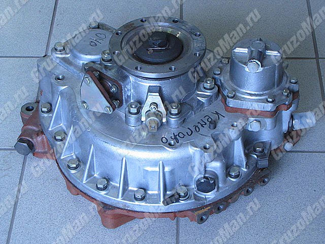
DISASSEMBLY AND ASSEMBLY OF THE DEMULTIPLICATOR OF THE YAMZ-239 GEARBOX
Disassembly and assembly of the demultiplier (see Figure 19) is carried out on a workbench using standard wrenches. To disassemble and assemble the output shaft, a press and a puller are used to press the shaft bearing. Parts and assemblies of the demultiplier intended for assembly must be clean, no traces of corrosion are allowed. Oil and air passages must be flushed and purged.
When disassembling and assembling, ensure that parts and assemblies are protected from damage. The use of steel drifts is not permitted.
When disassembling and assembling the output shaft, pressing and pressing in the bearing, apply the load to the inner ring. Shock loading is not permitted.
When installing gaskets, the presence of wrinkles, overlapping with gaskets of the connecting oil and air channels is not allowed.
The demultiplier is disassembled in the following order:
- disconnect the spacer 2 from the crankcase 1 (see Figure 19) by unscrewing fifteen M12 bolts with a wrench size S = 17 mm;
- remove the gasket 10 between the spacer and the demultiplier crankcase;
- unscrew the bolt 33 fastening the output shaft flange with a wrench with a spanner size S = 36 mm, while the shaft must be locked;
- unscrew the six M12 nuts securing the output shaft cover with a wrench with a spanner size S = 12 mm;
- remove cover 28 and gasket 44;
- remove the worm 34 and the gear ring 36;
- remove the retaining ring 38 from the bearing groove;
- remove the output shaft 6 with the planetary gear parts and the fork 56 from the crankcase, having previously unscrewed the forks from the axle housing 57;
| Video (click to play). |
- unscrew the bolts securing the pneumatic cylinder with the rod support;
- disassemble the output shaft with the bearing and parts of the planetary gear, during disassembly, pay special attention to removing the pins of the retainer 42 and the springs 59 (see Figure 20) in each spike of the tapered rings, the axes of the satellites are pressed out during disassembly;
Assemble the demultiplier in the following order:
- assemble the output shaft 6 (see Figure 19) with bearing 37 and a planetary gear with a preliminary check of the operation of the tapered ring retainers;
- check the operation of the retainers 42 (3 pcs in each cone ring, see Figure 20) when they are installed in the holes of the studs of the conical rings (after installing the spring and the pin, force the pin into the hole of the stud by hand, compressing the spring, while the end of the pin should sink into the hole of the spike, protrusion of the pin beyond the outer surface of the spike is not allowed, after removing the load on the pin, the latter should return to its initial position under the action of the spring, jamming of the pin in the hole of the spike is not allowed);
- install tapered rings 41 (see Figure 20) with retainers 42 in the grooves of the ring gear 40 (after installing the rings, the latter should have a radial play relative to the ring gear of 1.0 mm, at least when a force of 8 kgf is applied, no more);
- check the pull-out force of the tapered rings from the fixed positions (the pull-out force should be within 64.84 kgf);
- satellites 43 (see Figure 19) on axes 19 must rotate freely without jamming;
- Install the assembled output shaft 6 together with the range switching fork 56 into the demultiplier housing 1;
- install a retaining ring 38 on the outer ring of bearing 37;
- install the bearing cover 28 of the output shaft 6 with shims 47 (the procedure for determining the total thickness of the shims is given below);
- assemble a pneumatic cylinder with a rod support 19 and sealing parts (rings 17, cuffs 18), install the rod into the support from the side of the slot in the support, which will protect the sealing rings in the support from damage;
- install a pneumatic cylinder with a support in the crankcase, ensuring the connection of the rod with the fork spike and centering the support along the hole in the crankcase;
- install flange 30 of the driveshaft drive, securing it with bolt 33 with the installation of washer 32;
- pin the bolt 33 with a cotter wire;
- install the retainer 11 and the spring 13;
- install a switch-signaling device for switching the ranges of the demultiplier into the screw 12 of the crankcase;
- install spacer 2 with toothed clutch 4 using spacer 10, centering the spacer along two pins and fixing it with fifteen M12x50 bolts with a wrench size S = 17 mm (the tightening torque of the bolts should be within 8.10 kgf-m);
- check the ease of rotation of the output shaft when the high range is turned on and bolt 8 is removed, ensure the inclusion of the high range by supplying air under pressure within 8.8.5 kgf / cm2 to the right cavity of the air cylinder, after turning on the high range, the shaft should not turn by hand;
- screw the adjusting bolt 8 all the way into the piston rod (when the bolt rotates, an increase in resistance to rotation should be felt), repeat the operation several times, making sure that the stop is felt at the same position of the bolt head;
- turn the adjusting bolt from the position of its abutment to the end of the stem by 5 / 6.7 / 6 turns (5.7 faces of the bolt head). When turning the bolt, simultaneously turn the output shaft by the flange, at the end of turning the bolt, the output shaft should rotate freely by hand, while the force acting on the fork from the pneumatic cylinder is removed and the bearings of the fork will be unloaded;
- lock nut 9 with a torque of 14 to 16 kgf-m;
- check the engagement of the lower range and the ease of rotation of the output shaft, for which, on the output shaft, install the sun gear 21 (see Figure 2) with a coupling clutch 20, supply air to the left cavity of the pneumatic cylinder, make sure that the lower range is turned on, while rotation the output shaft must be free, without jamming, the sun gear must rotate together with the coupling, and when the sun gear rotates when acting on the coupling, no biting or jamming should be felt, and the output shaft must also rotate.
DETERMINING THE TOTAL THICKNESS OF THE DEMULTI-PLIATOR OUTPUT SHAFT BEARING GASKET
To ensure the axial play of the output shaft within 0.1 ... .0.5 mm, before installing the cover 28 (see Figure 19) on the demultiplier housing 1, install shims 47 between the end of the outer ring of bearing 37 and the end of the seating surface (groove) under the outer ring of the output shaft bearing.
The total thickness of the shims is determined by the following measurements (in accordance with Figure 52), while the measurement accuracy should be no more than 0.03 mm with a tight fit of the parts:
- determine dimension A from the end of the outer ring to the crankcase surface;
- put a sealing gasket 45 on the bonding surface of the cover, a thrust ring 46 on the end of the groove for the bearing and measure dimension B;
- determine the total thickness of the spacers S and the conditions: S = B - A + (0.15.0.2).
Before installing the demultiplier with a spacer on the main box crankcase and the spacer on the demultiplier crankcase, apply an anaerobic sealing compound UG-6 TU 6-01-1285-84 to the gaskets on both sides with a continuous strip 2-3 mm wide along the contour.
When installing the bearing cover of the input shaft (Fig. 1), the demultiplier with a spacer on the main box crankcase (Fig. 2), the rear bearing cover of the output shaft of the range (Fig. 3), ensure the minimum axial backlash of the shafts using shims selected as follows:
Measure the dimension "A" of the depth of the bearing bore in the bearing cap, taking into account the thickness of the gasket, with an accuracy of 0.1 mm (Fig. 1).
Measure dimension "B" from the end of the outer ring of the bearing to the surface of the crankcase wall with the bearing pressed against the stop with an accuracy of 0.1 mm.
Select the total nominal thickness of the shims S from the condition: S = [A - B - (0.2 ... 0.3)] mm
Measure dimension "A" (Fig. 2) from the end of the outer ring of the bearing to the surface of the crankcase with an accuracy of 0.1 mm, making sure that the centering ring is pressed against the stop, and the snap ring and bearing are firmly pressed against the center ring.
Measure the dimension "B" of the depth of the bearing groove in the gear coupling, taking into account the spacer and the groove with an accuracy of 0.1 mm.
Select the total thickness of the shims S from the condition S = [B - A - (0.2 ... 0.3)] mm
Measure dimension "B" (Fig. 3) from the end of the outer ring of the bearing to the surface of the crankcase with an accuracy of 0.05 mm, making sure that the snap ring and the bearing are firmly pressed against the surface of the crankcase.
Measure the dimension "D" from the gasket to the thrust ring in the cover groove with an accuracy of 0.05 mm.
Select the total nominal thickness of the shims S from the condition: S = [G - B - (0.15 ... 0.2)] mm
Tighten the range-multiplier housing mounting bolts in two steps (see the "Tightening torques" table).
Tightening sequence according to fig. 4.
When repairing the range multiplier with replacing the synchronizer parts, adjust the required stroke length when the upper range is turned on, ensuring the unloading of the fork crackers when operating at the higher range, for which:
1. Turn on the high range in the range multiplier by supplying air under pressure from 784 to 833 kPa (8. 8.5 kgf / cm 2) into the rear cavity of the pneumatic cylinder, make sure that the high range engagement clutches are fully engaged. When fully engaged, the indicator lamp should go out, the propeller shaft mounting flange should not rotate by hand.
2. Screw the adjusting bolt against the stop in the piston rod (as the bolt rotates, an increase in resistance to rotation should be felt). Repeat the operation several times, making sure that the stop is felt at the same position of the bolt head.
3. Turn the adjusting bolt from the position of its stop to the end one turn (5 edges of the head) and while holding it in this position, lock it with a lock nut, tightening it with a torque of 137-157 N · m (14-16 kgf · cm). After adjustment, the propeller shaft mounting flange should turn easily without jamming, by hand. Turn the flange through an angle of at least 360˚.
Attention! Incorrect adjustment causes overload of the range fork crackers, which leads to their rapid destruction.
4 Install the range multiplier on the gearbox with the vertical position of the axes of the main gearbox shafts. The output shaft of the range-multiplier should be cranked by hand with any range on and off in the main gearbox.
YaMZ 238 is a diesel engine with 8 cylinders. The YaMZ 238b variant is found on such powerful machines as MAZ, Ural, and construction transport equipment. These cars are distinguished by a large margin of productivity.
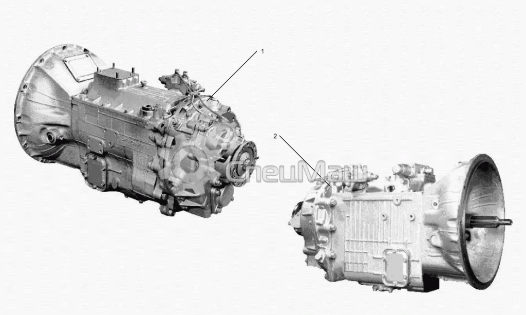
The structure of YaMZ-2381 (8-speed manual transmission) includes a 4-speed gearbox and a 2-range demultiplier (short divider), which is designed to increase the torque. The YaMZ-238VM model meets the necessary environmental standards. The presence of an additional box is typical for trucks. The diagram of this box shows the presence of a propeller shaft mounting flange here. It should be noted that YaMZ gearboxes can be designed not only for 8 gears, but also for 5, 6, 9, 14.
YaMZ device The version of the YaMZ-238A is discontinued. Models 238ВМ4 (5) (7) are an excellent alternative to it.
There are synchronizers in all forward gears.Synchronizers provide not only smooth running, but also silent gear shifting.
An air distributor is an integral part of the YaMZ 238b checkpoint. This device provides direct switching of air flows. The mechanism is securely fixed in the upper crankcase cover.
The article of the gearbox housing for YaMZ 238 - 1701015. This element has a solid foundation, is part of the transmission system. Its main function is to ensure the protection of gearbox parts from the effects of dirt, water, dust. Shafts, bushings, gear blocks, couplings, nuts are designed for a long working period.
The driver of a vehicle, where there is such a gearbox as YaMZ 238, must timely visit the TO, where service workers using computer equipment can fully check the automotive system. Self-care of the gearbox may mean that the owner of the car can change the oil, flush the crankcase. For flushing the crankcase, it is advisable to use special liquid industrial oils that comply with GOST.
The frequency of when to change the oil directly depends on the driving style of the car owner.
The replacement of individual component parts on the YaMZ 236, 238, 2381, 239 gearbox can be indicated by the fact that the oil poured into the crankcase overheats, characteristic noises from the gearbox side have appeared. The repair may consist in the installation of new shafts, bearings, seals and other consumables that relate to the gearbox.
Many cars of the Minsk Automobile Plant are equipped with engines from the Yaroslavl plant. Most often, these are motors of the 238th and 239th series, under which the corresponding gearbox is installed. For example, the YaMZ 238 scheme in the base provides for the installation of the same box. Our article will be about the latter ...
To be absolutely precise, we will tell you something about those units that are equipped with a special device that allows you to expand the capabilities of a standard box without undue interference in the design. We are talking about the YaMZ 238 gearbox with an increase demultiplier, or as it is otherwise called a divider. We will also use this word, because on trucks, another additional box is often used, which is also called a demultiplier, but it has a slightly different task, and we will talk about it in another article.
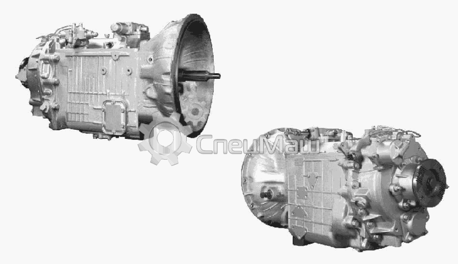
In essence, a divider is the same gearbox, only it has only two speeds - standard (direct), in which torque is transmitted in the same way as in normal operation, and increased, in which the torque is average for two adjacent numbers. That is, for example, the torque of the third gear with the included demultiplier-divider will be equal to the arithmetic mean between the torques of the third and fourth direct gears.
Thus, the design diagram of the YaMZ 238 gearbox remains practically unchanged, and since the divider is installed in front of the main box, the number of output speeds remains the same. But due to the use of the divider, the driver gains an additional advantage - it becomes possible to more accurately regulate the engine power in accordance with the load and the speed of movement.
Consultation on technical issues, purchase of spare parts 8-916-161-01-97 Sergey Nikolaevich
This control allows you to reduce overall fuel consumption and at the same time protects the parts of the main box. However, if you are with us, then you don't have to worry about spare parts for the YaMZ 238 checkpoint, as well as spare parts for demultipliers and dividers - whatever you need in SpetsMash, this part is sure to be found.
And do not worry about the quality of spare parts, because it has been tested by many specialists, including representatives of Yaroslavl Motorny. As for the prices for our products ... so we are not intermediaries, and we do not need to "bully" them, so most spare parts are cheaper than at YaMZ itself. You can check!
Listening to the polemics of the drivers of MAZ vehicles and those displeasure with the YaMZ-238 checkpoint, you involuntarily read over the options for installing other checkpoints. I personally had no complaints about the YaMZ-238 checkpoint. Well, not in a hurry to change gears. Yes, not quite easy gear shifting, thoughtfulness in cold weather in shifting the demultiplier. Here, apparently, basically everything, no later, it appeared and I have a complaint - a small gear ratio of the first gear, or it would be better to also make a creeping gear to it. But no matter how it was, on three cars I had a YaMZ-238 checkpoint and thank God it was successful. In addition to the oil seals and the plates of the de-duplicator synchronizer, I did not buy anything for it. Spare parts B./U. of course I did. After talking at some point with the aggregator at these checkpoints and telling him my experience of communicating with the box, I heard such a conclusion from him. You are just very lucky, we suffer with them, bearing breakage on the intermediate shaft and breakdown of the secondary shaft are quite common. As soon as I switched to the 238 checkpoint, I immediately got rid of all 236 boxes.
But now the main thing. If we have a YaMZ-238A checkpoint on the MAZ-54323, then with modern tubeless tires with a size of 315 / 80-22.5 having a statistical rolling radius-0.499 meter speed characteristic will be as follows;
The maximum speed will be as follows 102.158 km / h.
If, for any reason or desire, we install a five-speed gearbox instead of the YaMZ-238A gearbox, then with the same rubber we will get other speeds.
As you can see from the table, the speeds will become such, but it's no wonder, because the gearbox range has decreased significantly.
The maximum speed has become 109,897 km / h. As you can see from the table, the maximum speed has increased, but the starting speed in the first gear has also increased. And also the car, through this gearbox, has become less adapted to changing road conditions. And it will be more difficult for the driver to select the engine speed in the green zone of the tachometer.
But suddenly, due to some fortunate coincidence of circumstances, you fell into the hands of a new six-speed gearbox of the Yaroslavl plant and you decided to install it. How the speed characteristic will change. To do this, take and calculate.
As you can see from the tables, the maximum speed will be 96,70 km / h. Looking at the speed table of a six-speed gearbox, one can easily conclude that it is preferred to use instead of the widely and long-known YaMZ-236.
If you decide to put a KAMAZ gearbox with a divider, then the speeds will be as follows.
At 10, the increased speed will be 89.54 km / h.
If we got a YaMZ-238 gearbox 12 Fas Gear with a flywheel casing, then we will count again to get the result.
View of the checkpoint 12-speed FAS GIR.
If we found and installed an eight-speed gearbox V 8 with Renault, then by counting the table we get the following results.
Let's look at the maximum speed with this checkpoint, it = 96,70 km / h.
If we put the checkpoint B-9, we get the following table. In principle, the B-9 differs from the B-8 gearbox only by the addition of a creep gear.
Accordingly, the maximum speed from the V-9 checkpoint will also be equal to 96.70 km / h.
If we adjust the B-18 checkpoint, we will get the following results.
As you can see, such a gearbox with a large range and 18 gears allows you to accelerate the car to 111,59 km / h.
If we decide to install a ZF-8 or ZF-9 gearbox, then the difference will again be in addition to the creep gear ZF-9 gearbox.
Let's calculate the speed at the checkpoint 9S1310TO,
The maximum speed of these checkpoints will be the same and equal 96.70 km / h, but the ZF-8 will not have a creep transmission.
External view of the ZF 16S 1820 TO /
We make a table of speeds for this checkpoint.
As you can see from the table, the maximum speed will be 86.35 km / h.
In case of faults in the MAZ gearbox, the crankcase and the cover are subject to repair.
All other mechanisms with significant wear or damage must be replaced.
Urgent repair of the gearbox cast-iron crankcase is carried out if:
- Bores for bearings and pins are worn out;
- The thread is damaged.
To repair the checkpoint at MAZ, bushings are installed.
The hole must be bored to d fifteen and a half centimeters, and the groove is made three millimeters larger in diameter.
- The depth is two point five tenths of a millimeter.
- Bushings must be pressed into the prepared sockets.
- Provide tension not> 0.15 mm.
- The holes are bored linearly.
To repair the MAZ 238 gearbox of damaged threads, glue screwdrivers are used.
If the M16 holes are worn out, drill with a diameter of 17.1 mm. Thread cutting is done. Then the screw is screwed in.
- Reaming is performed to repair the holes.
- When repairing a MAZ gearbox with a crankcase divider, it is necessary to comply with the established requirements of the manufacturer for the interposition of surfaces.
Restoration and repair of the MAZ gearbox of the cast-iron cover is carried out when:
- Cracks;
- Worn out holes;
- Damage to the ends.
If even the smallest breaks are visible on the pipe, it is necessary to cut off the deformed section. Then, the hole d is bored five and a half centimeters for the repair sleeve.
The chamfer is grinded 5x45 degrees. A sleeve is pressed into the prepared hole. The part in the process of repairing the MAZ checkpoint is welded with its own hands. Grinding and boring of holes is carried out.
Having placed the lid in the cartridge, the butt is trimmed. The hole is grinded, and the chamfer is bored. Then four turns are cut. They observe a step of four, a width of three, and a depth of one millimeter.
The final processing and repair of the MAZ gearbox with their own hands is done on a circular grinding machine.
- The damaged bolt holes are welded with an electrode.
- The fusion is cleaned.
- Drill small holes d eleven millimeters and countersink them from the side of the pipe.
When repairing a MAZ checkpoint, the covers strictly comply with a number of requirements:
- Runout of the holes for the oil seal - no more than 0.08 millimeters;
- The permissible non-parallelism of the ends of the flange and the groove is no more than 0.05 millimeters;
- Runout of the surface of holes with a groove is not> 0.02 mm.
If the hole for the oil seal is worn out, a bushing is used to repair the gearbox at MAZ. First, bore with a diameter of 68 mm and a length of 24.5 mm. Then the bushing is bored. The hole is aligned with the oil groove in the cover. The end of the sleeve is trimmed. Chamfer and hole are bored.
Repair of the MAZ gearbox with a divider is performed on special equipment.
Do not forget that in our online store you will find the highest quality MAZ spare parts for gearbox repair.
The YaMZ-236 gearbox should be disassembled only if necessary: for repair or replacement of worn or damaged parts.
To remove the gearbox from the engine, it is necessary to unscrew the bolts securing the clutch housing to the flywheel housing, first bending the lock washers, then move the box back so that the input shaft comes out of the clutch and lower it down. In this case, it is necessary to support the box from below or hang it from above in order to avoid damage to the clutch disc and the input shaft of the box.
After the gearbox is removed from the engine, it must be cleaned of dirt and oil, flushed outside and the oil drained from the crankcase.
Disassembly of the box must be carried out in the following order:
- remove the clutch drive parts from the box;
- unscrew the nuts securing the remote mechanism and remove the remote mechanism of the YaMZ-236 gearbox; unscrew the nuts and remove the support with the YAMZ-236S gear lever;
- unscrew the bolts securing the top cover to the crankcase and remove the top cover;
- unscrew the bolts securing the oil intake cover and remove the cover with a magnet and mesh; clean the intake mesh and magnet from dirt and metal particles and rinse in kerosene;
- unpin and unscrew the nut of the universal joint flange and remove the flange;
- unscrew the bolts securing the secondary shaft rear bearing cover and remove the cover with the oil seal and speedometer drive gears; remove the worm of the speedometer drive; remove the spacer sleeve from the YaMZ-236S gearbox;
- unpin the bolts securing the input shaft rear bearing cover and remove the cover with the oil seal; remove the input shaft with the bearing;
- remove the rear bearing of the secondary shaft and remove the secondary shaft assembly with gears and synchronizers;
- unpin and unscrew the bolts of the oil pump and remove it;
- unscrew the bolts and remove the intermediate shaft rear bearing cover;
- press out the axis of the reverse gear block and remove the block with bearings;
- unpin and unscrew the bolts securing the thrust washer at the rear end of the intermediate shaft, remove the washer and press out the rear bearing of the intermediate shaft;
- remove the intermediate shaft assembly with gears. Further disassembly can be carried out without special explanation. It must be remembered that pressing the gears from the intermediate shaft should be done with support on the hub, but not on the gear rim, in order to avoid damage or deformation of the gear.
The YaMZ-236 gearbox is assembled in the reverse order. When assembling, special attention should be paid to the correct installation of the gaskets, in which holes are punched for the passage of oil.
If, when disassembling the gearbox, the oil pump was also disassembled, then before assembling it, it is necessary to lubricate all the parts and the inner cavity of the pump casing with oil for lubricating the gearbox, since a dry pump may not be able to suck oil from the oil bath of the gearbox crankcase.
For the transmission to function properly, it must be precisely aligned with the engine. To do this, before installing the box on the engine, you should check that the mating surfaces of the flywheel housing and clutch housing are clean, without nicks and after installing the box they are tightly bolted. The bolts must be tightened in two steps: first, all the bolts are tightened with half the effort, then with the full torque of 30-32 kgm.
Whenever the gearbox and clutch are removed from the engine, remember to lubricate the input shaft front bearing in the engine crankshaft.

