In detail: do-it-yourself KAMAZ backstage repair from a real master for the site my.housecope.com.
Are you here "Club of owners and fans of KAMAZ cars" Transmission "gear lever
Please tell me how to adjust the wings. I changed all the crackers for new ones, the speeds still turn on poorly, I don't think about the box.
It seems to have figured out, there are two retainer bolts that hold neutral in the box and on the lever. Tomorrow I will try.
tell me how to adjust the rocker that comes with the tips?
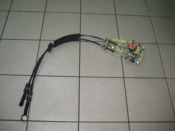
Hello everyone! Take the newly-made KAMAZist. I want to put my thoughts on the stage. It is no secret that this design is not the most successful (a hole in the cockpit, excess noise and vibration). I had to work on a Japanese truck, where the curtain is cabled. It consists of two cables, not so complicated. Here I think what the Europeans are. I plan to get to the disassembly, see and, if anything, buy the necessary parts. What are your thoughts on this?
If you have the time and desire, you can do anything.
The hole will be either one for the lever, or two, for the cables (when installed in the cab). Tell me who knows what construction is in Scania, Manach, etc.?
In general, in my opinion, this idea is not a bad idea. To weld an oval hole under the wings in the cockpit, and put a rope wing, and not necessarily in the same place. It can be like on the 503m MAZ, in the floor. The KAMAZ wing is quite a convenient and reliable thing, but the noise and heat kill in the summer. If you try and succeed, be sure to sign off what and how you did, where you took what from, with photos!
If you try and succeed, be sure to sign off what and how you did, where you took what from, with photos!
I will definitely start with the showdown. One thing is confusing, what to do with the divider flag.
Either a lever handle from a foreign car, or a key and PEC.
I came up with and remade the gearshift mechanism for KAMAZ. The opening for the lever in the cockpit was closed and the cockpit became absolutely noisy. The shift lever no longer makes noise, no shivers, no squeals. No more noise and warm air from the engine is supplied to the cab as the opening is closed. The mechanism is located in the cab, a very convenient lever can be adjusted at the discretion of the driver. Gear changes easily. Who is interested, please contact: or by phone: 8-928-494-06-73
some of my friends put the lever "under the euro", but I will not make up my mind
Repair and adjustment of the gearshift lever KAMAZ!
How to adjust the rocker Kamaz, the bolts on the guitar divider and replace the crackers on the house!
KAMAZ speed does not turn on
I remove barking on KAMAZ
Repair of the gear shift
ZF gearbox on KamAZ 6520. Location and gear shifting.
Detailed disassembly, troubleshooting of the KAMAZ gearbox with a Divider.
How to use a divider on a KAMAZ correctly
Backstage repair and a few words about the clutch (e34)
The plans are purely for convenience and for beauty. technically kamaz in excellent condition
hello, what is your body height, how many tons does it take?
Hello. Kamaz was 180 and the trailer was 175. I did not load full wheat, I carried it for 30. I took 33 barley without bumps. Good seed 24
clear). I'm going to make a body for myself
Cool Kamazik! Want to take a grain truck? Tell me which one is better to buy and for how many rubles can you find a decent option? I would be grateful for any advice! Still wondering how much money should be left approximately for repairs, if that?
ksati kamazik we sell this) not interested?
Guys KAMAZ drivers help out, we open a small car shop in our city for the sale of spare parts for KAMAZ, mainly on order, but we want to buy a batch of consumables and the most breakable spare parts for these cars, nowhere can I find a list of the most necessary things, as in your opinion, what is most often needed for such cars, I myself have never owned or driven such a car. Please help me with at least a minimal list.
How to adjust the rocker Kamaz, the bolts on the guitar divider and replace the crackers on the house!
HOW TO POST KULISE ON KAMAZ.
KAMAZ speed does not turn on
Repair and adjustment of the gearshift lever KAMAZ!
The rocker of the KAMAZ checkpoint revision
Do-it-yourself backstage repair or what to do if the gearshift lever is hanging out
Kamaz 65116 reystylingovaya cabin EURO-3
ZF gearbox on KamAZ 6520. Location and gear shifting.
In this article, I would like to share the experience of repairing a KAMAZ vehicle gearbox, namely a model 152 gearbox. This gearbox model is practical and quite hardy, but during operation due to violations associated with its maintenance, it fails. The first thing you have to deal with during repairs is the lack of the required level of transmission oil in the crankcase, instead of the prescribed 12 liters, you can hardly find 3 liters of oil. And there is no need to talk about the fact that this oil was changed in due time. Some find nigrol somewhere, and if you add to it the quality of the spare parts sold, you don't have to think about the cause of the breakdowns for a long time. All this leads to the destruction of bearings, fragments and rollers of which fall between the teeth of the gears, break them, or in the absence of a properly working clutch, the gears themselves are destroyed.
You have decided to repair the checkpoint without resorting to the services of a repair plant. If the breakdown of the gearbox did not entail mechanical damage to the housing or the wear of the bearing seats does not exceed the standard value, then the bearings of the synchronizers and gears can be replaced independently, in a normal workshop. It is not very difficult and does not require the use of special technologies. The only thing I want to warn you against replacing the countershaft gears. The gears are seated and in order to dismantle them, it is necessary to use a hydraulic press and appropriate devices, in their absence, this may either not give any results or lead to injury.
We disassemble the gearbox, first of all, remove the gearbox cover, then remove the input shaft. To do this, it is necessary to remove the cover of the rear bearing of the input shaft and knock out the bearing, the shaft with it comes out of the gearbox housing, when removing the cover, be careful, with fastening bolt stoppers, as a rule, it is difficult to find them in spare parts stores. Having removed the input shaft, we need to unscrew the coupling nut, keep in mind that it has a left-hand thread, by unscrewing the nut, remove the washer and the synchronizer clamping ring, then remove the bearing and change it to a new one.
We remove the secondary shaft in failure, for this it is necessary to remove the bearing cover of the secondary shaft, and through the technological holes of the gear of the first gear, knock out the rear bearing of the secondary shaft, the task is not very simple, be careful not to damage the gear and the gearbox housing. Having removed the bearing, we can remove the output shaft assembly from the housing. The most convenient way to do this is with a non-rigid wire, one end of which must be fixed to the first gear gear by pushing it through the technological hole, the other end is fixed to the synchronizer ring. The shaft is heavy, it is best to take it out together, since it is necessary to direct the gear of the first gear so that it does not cling to the gearbox housing.
Having removed the output shaft, we have the ability to replace the gears: first gear, reverse gear, second gear and the synchronizer for second-third gears. In order to replace the gear wheel of the third gear, the gear wheel of the fourth gear and the synchronizer of the fourth - fifth gears, it is necessary to remove the support roller bearing, for which we remove the retaining ring, it is most convenient to remove the bearing using a puller.
We remove the block of reverse gears, for this we unscrew the locking bolt of the stopper and remove the stopper, then from the inside of the gearbox we knock out the shaft and take out the block of gears.
To remove the intermediate shaft, it is necessary to unscrew the cover of the spherical roller bearing, loosen the bolts securing the support washer, loosen the bolts and remove the washer. The spherical bearing is located in the glass; it is most convenient to remove it from the housing together with the glass.Then the shaft can be easily removed.
We have completely disassembled the checkpoint, now you can make defect detection of parts and, if necessary, replace them with new ones. What you need to pay attention to:
- all spline joints should not have visible wear and tear
- it is advisable to replace the roller bearings of the gears, having carefully examined the places of their rolling, whether there is any wear or places pressed by the rollers
- it is also advisable to replace the bearings of the shafts, since, due to the breakdown and the ingress of metal shavings and fragments into the oil, the rolling points of the bearings are likely to be damaged, which will subsequently lead to a repeated breakdown of the gearbox.
- Carefully inspect all the gears for chips, shells, unacceptable contact spots and wear of the gear teeth, I want to repeat, it is not advisable to change the countershaft gears yourself, you most likely will not succeed, at best you will ruin the shaft at the worst you will injure yourself.
- tapered synchromesh clips should not be set on fire and worn out, the guide shafts should not dangle and there should be no signs of wear or chips on the splines.
Assembling the checkpoint is necessary in the reverse order. We place the intermediate shaft in the gearbox housing, install the front roller bearings and the rear spherical bearings with a glass. We fasten the support washer, lock it and close the rear cover of the spherical bearing fastening, after installing the gaskets. The shaft should rotate easily by inertia, while there should not be even the slightest jamming and biting of the shaft.
If the intermediate shaft rotates easily and freely, proceed to installing the reverse gear block. We install the axial displacement washers in such a way that the stoppers in them fall into the grooves of the gearbox housing, guide the gear block along the shaft and insert the shaft, lock it with a locking plate.
We collect the input shaft. We put the bearing on the shaft, paying attention to the groove of the retaining ring in the bearing, it should be located from the gearbox housing. We put on the clip. We put on the washer. We tighten the nut. The shaft is now ready for installation.
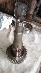
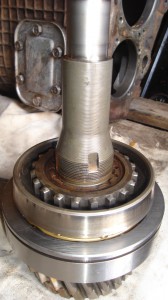
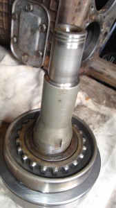
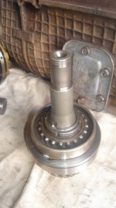
We collect the secondary shaft. First of all, we install the gear wheel of the third gear, having previously installed the roller bearing, then we install the gear wheel of the fourth gear assembled with a glass and set rollers.
We install a stopper with a spring in a special groove on the shaft and a support washer. We turn the washer along the groove in the splines of the shaft, having previously sunk the stopper until the stopper clicks. Here, pay attention to the fact that the stopper is not jammed, it is freely squeezed out and returned by the spring, becoming in its seat. If the stopper moves tightly, this can lead to the fact that it will be able to release the support washer, and it will turn along the splines and the gear wheel of the fourth gear will begin to move freely along the splines, which will lead to the rollers falling out, and therefore, the gearbox will fail. synchronizer of the fourth fifth gear. Pay attention to the fact that on different sides it has different spline diameters, put its spline parts correctly, according to the splines of the mating parts. Install the support roller bearing so that its support washer is pressed against the spline part of the shaft, and then install the circlip ...
On the other part of the shaft, we install the second-third gear synchronizer, pay attention to the fact that the protruding part of its splines is directed towards the input shaft. Install the roller bearing and the second gear gear, making sure that the bevel part of the gear is directed towards the synchronizer ...
We install the glass and the roller bearing of the reverse gear, while the holes of the oil channel on the shaft and the glass must match, we install the clutch and the glass with the roller bearing of the first gear gear, install the first gear. Install the support washer.
The output shaft assembly is placed in the gearbox housing.We install the rear bearing of the output shaft in the gearbox housing. We put the input shaft assembly.
Now our task is to install the covers of the rear bearing of the input shaft and the rear bearing of the secondary shaft, they must tightly press the bearings against the gearbox housing, so that the bearings cannot rotate in the housing. For this we use shims. When choosing shims, we take into account the thickness of the cover gaskets so that pressing the bearing, the cover is tightly pressed against the gearbox housing.
After installing the rear cover, install the propeller shaft mounting flange and tighten the nut.
Before installing the upper gearbox cover, we check: whether the gear shift forks are dangling on the shafts, and in what condition the crackers are, it is better not to touch them without the need, in the store you will usually buy homemade products of incomprehensible quality. And in general, spare parts in unscrupulous stores are designed for the level of a KAMAZ operator who repairs his car himself, and cannot independently judge the quality of a spare part, and therefore marriage flourishes.
As you can see, we did not encounter anything complicated when assembling the checkpoint, attention and accuracy are more important here, check each step for yourself, the rush will result in a malfunction.
And do not skimp on good transmission oil, the fact that the KAMAZ gearbox should work on nigrol is an old-fashioned delusion.
Gearboxes of the 14th and 15th families on KAMAZ vehicles are equipped with a mechanical drive for controlling the shift mechanism. This design is very simple and reliable enough, but over time it stops working properly. At first, the clarity of the movement of the gear lever disappears, then the gears are not fully engaged and periodically "fly out", and, finally, there comes a moment when it becomes very problematic to turn the gear on or off. So that the breakdown does not worsen, it is important to diagnose the gearbox in a timely manner, identify the problem and professionally eliminate it, for example, by repairing the backstage of the Kamaz gearbox. The malfunction of the gearshift mechanism is a violation of the rigidity of its kinematic scheme. The reason, as with any mechanical system, is the wear of the parts. As a result, backlash appears in the joints and the accuracy of the mechanism is reduced. Accordingly, you have to do more manipulations and increase the forces when shifting, which only accelerates the wear process. This leads to the fact that transmissions are not included in Man, Kamaz, Volvo, Scania and other trucks.
Control unit maintenance
Replacement of synchronizers, bearings
Replacing the clutch fork repair kit
Assembling an already disassembled checkpoint
The demultiplier carrier burst
Replacing the brake clutches
Replacing the front divider piston o-rings
Replacing the 3-4 gear synchronizer
Differential housing replacement
Shank seal replacement
We determine the cause of the breakdown with 99% accuracy
with the help of a professional
dealer equipment- Definition of symptoms: what makes noise, what does not turn on. Traces of oil leaks are fixed
- Drain the oil and check its condition, e.g. emulsion or burnt oil, etc. The presence of traces of wear or parts of destroyed parts in the oil.
- Until the moment of disassembly, the axial play of the shafts is measured.
- Upon disassembly of the gearbox, parts with obvious wear or destruction are rejected
- Further, parts and assemblies that do not have obvious damage or wear are checked for compliance with the standards
- Cleaning of parts in a special installation, and at the final stage it is already possible to track cracks, burns, undulating notches, chips, etc.
in 30% of cases, the cause of the breakdown is not in the gearbox itself, but in the adjacent vehicle systems
The cost of repairing which is often much lower than repairing the checkpoint itself
Gearbox shift drive mechanism
Control electronics for shift or clutch actuator
Choose your version
- The client formulates his problem
- We carry out diagnostics to determine the true cause of the breakdown
- Dismantling the unit or repairing adjacent systems
- Unit washing. Disassembly, defect detection, budgeting
- Selection and purchase of spare parts
- Repair work
- Assembly and installation of the unit on the car, oil filling
- Test drive, output diagnostics
You know the reason for the breakdown
- Dismantling the unit or repairing adjacent systems
- Unit washing. Disassembly, defect detection, budgeting
- Selection and purchase of spare parts
- Repair work
- Assembly and installation of the unit on the car, oil filling
- Test drive, output diagnostics
- Dismantling the unit
- Unit washing. Disassembly, defect detection, budgeting
- Selection and purchase of spare parts
- Repair work
- Loading the unit
How do tech services cheat their customers?
First of all, we strive to help the client, and then make money.
Therefore, we openly guarantee repairs from the 1st time.Examples from our practice, when services unfairly profit from clients
1) In the estimate for the repair, they indicate the details of the production of ZF or Euroricambi, and in fact install the details of the production of CEI (cheaper and much lower quality). The benefit can be several tens of thousands of rubles
Examples from our practice, when services unfairly profit from clients
2) In the estimate for the repair, new parts are indicated, and in fact the used parts are installed. The benefit can be several tens of thousands of rubles
Examples from our practice, when services unfairly profit from clients
3) They can cheat when troubleshooting, i.e. slip worn and defective parts from another box, you pay and you will have new parts in the box, and your serviceable ones will be used according to scheme number 2
Examples from our practice, when services unfairly profit from clients
4) Oil fraud schemes are also frequently implemented. Instead of oil of the proper specification, anyone who is at hand or even used oil can be poured! Doesn't fit in your head right? But it fits in the pocket, usually of an ordinary locksmith staff 2-3 thousand rubles.
Thanks to modern European equipment and a high culture of production, you can not think about the quality of repair with us.
Tool storage area, stainless steel workbenches.
Professionalism and the availability of the necessary means of production allow us to maintain a high rate and productivity of labor during disassembly, troubleshooting and assembly of the unit.
Tool storage area, stainless steel workbenches.
Modern electrical equipment allows us to repair any electronic systems of trucks. We also have dealer diagnostic equipment, so you don't have to worry about the accuracy of the breakdown and the quality of repairs.
Press, Goose crane, Stacker
The service is fully equipped with all the necessary, expensive equipment, allowing to carry out repair work of any complexity at the proper level of quality.
Before starting repair work, we wash all the parts of the unit in a special wash, which removes all old oils and dirt from the mechanisms, which will have a beneficial effect on work in the future and greatly simplify the repair process.
Repair of all units is carried out on a special tilter, which fixes the part in a position convenient for access by any tool. At the same time, not a single detail is lying somewhere on the floor, as in most services.
We will prepare all the necessary documents for you, pick up any part within 15 minutes and check its availability in the warehouse. We will also provide you with all the necessary information on the repair and maintenance of your truck.
Gear shifting mechanism (fig.a) is assembled in the upper cover 2 of the gearbox housing and consists of three gear shift rods, gear shift forks 3, 5, 6, a locking mechanism, three rod position latches, a fuse for engaging the first gear and reverse gear, lever 20 (see Fig. . 1) and stock.
Inside the cover there are lugs for the passage of the rods, and in the front part of it there are three vertical holes for installing the rod clamps and one horizontal hole for mounting the balls of the locking mechanism.
In the front part of the cover on the right, there is a breather 12 (Fig. 1 b) of the gearbox.
To protect against accidental engagement of the first gear and reverse gear, an upper horizontal hole having two diameters is made on the front right.
A pusher 15 of a fuse and a fuse are installed in the small diameter hole.
The large diameter hole has a thread for attaching the glass 13.
Spring 14 is installed in the blind hole of the glass.
Each rod is designed to engage two gears: rod 18 for fourth and fifth gears, rod 17 for second and third gears, rod 20 for first gear and reverse gear.
To fix the rods, each of them has three holes, where balls 7 come under the action of the springs (Fig. 1 c).
To prevent the simultaneous engagement of two gears, a locking device is intended, consisting of a pin 11 and two pairs of balls 10, 19.
The balls are located between the rods in the bushings, the pin is in the hole in the middle rod between the balls.
The diameters of the balls and the distance between the rods are chosen so that when any rod is moved from the middle position, the balls come out of the holes of the moving rod and enter the holes of the stationary rods, blocking them with the body.
The shift forks of the corresponding gears are installed on each rod. The forks are fixed to the rods with set screws, which are secured with a cotter wire. The shift fork of the first gear and reverse gear has machined tabs with which it enters the groove of the carriage for shifting the first gear and reverse gear. At the ends of the forks for shifting the second and third gears there are holes in which crackers are installed; crackers enter the groove of the second and third gear shift synchronizer carriage. The ends of the forks of the fourth and fifth gears end with a machined surface in which there are grooves. The fork grooves include a fourth and fifth shift synchronizer ring.
To move the rods and engage the required gear on the rod of the first gear and reverse gear and on the rod of the second and third gears, the heads of the rods are installed, fixed with set screws; the shift fork of the fourth and fifth gears is made integral with the head. In the heads of the rods and in the head of the shift forks of the fourth and fifth gears there are grooves that coincide in the neutral position and provide unhindered swing of the lever in the transverse plane relative to the axes of the rods.
In the neutral position of the gearshift lever, lever 20 (Fig. 2) is in the middle position and its tab enters the groove in the head of the second and third gear shift rod. When the gear lever is moved from the neutral position to the right and left, the lever 20 rotates relative to the axis of the rod and enters the groove of the head of the rod of the first gear and the gear of the rear entry. When the lever 4 for shifting the gearbox moves forward or backward, the rod 19 moves, which, in turn, moves the lever 20. The lever 20 moves that rod of the gearshift mechanism, in the groove of the head of which it is located.
To prevent accidental engagement of the primary and reverse gears, a safety pusher 25 is installed in the opening of the head 23 of the fork rod of the first and reverse gears,which, under the action of the safety catch 24 and the spring, constantly rests against the lever 20 when it is in the neutral position. The fuse 24 enters the hole of the head and prevents it from moving in the longitudinal direction. When the first gear or reverse gear is engaged, the lever 20, turning, acts on the fuse pusher 25, which, in turn, moves the fuse 24, compressing the spring and disengaging it with the head 23.
The lever 20 has a split head and is mounted on the rod 19 with a key and tightened with a tightening bolt. The stem 19 from the outside ends with a flange intended for connection with the flange 18 of the rod 17 of the remote drive. The stem moves in a spherical bearing. On the right side of the support, a set screw 21 is screwed in, with which the lever 20 is fixed in the neutral position during adjustment work. In working position, the screw must be screwed in 21 mm and locked with nut 22.
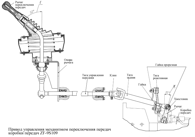
The remote control drive of the gearshift mechanism consists of a swinging lever 4 for shifting gears, support 2 of the lever, front 10 and intermediate 17 rods with an adjusting flange 18.
Lever support 2 is installed on four bolts at the front end of the engine block. A set screw 9 is screwed into the support body 2 from below, locked with a lock nut 8. The screw 9 is designed for correct installation and adjustment of the gearshift control drive. In working position, the screw must be unscrewed by 31 mm and locked.
The front link 10 is mounted on two spherical bearings in the engine camber along the left bank of cylinders. The front thrust bearing is located in the gear lever support, the rear one in the flywheel housing. The support cavities are filled with grease. The front and rear supports are structurally made in the same way and each consist of two bushings 13 with internal O-rings 12, two crackers and a spacer spring 14. The front and rear parts of the rod end with cylindrical journals, on which the segment keys are installed: in the front - the tip lever 7, in the rear - lever 16 with a ball head for connection with the cylindrical hole of the intermediate link lever.
The intermediate rod 17 is made integral with the lever, into the cylindrical bore of which the ball head of the lever 16 enters. An adjusting flange 18 is screwed onto the threaded part of the rod, with the help of which the rod is connected by four bolts to the rod flange 19. The rod assembled with the rod is mounted on two spherical supports: one thrust bearing is located on the clutch housing, the other on the gearbox. The spherical thrust support is structurally made in the same way as the front thrust supports, their elements are interchangeable.
Category: DIY repair
Characteristics of the car: The dimensions of the car are as follows, length - 3045, width - 1100, height - 1635 mm. The wheelbase is 2051 mm. The ground clearance is 163 mm. The car is equipped with a hybrid power unit. The 4-cylinder engine is equipped with a system that provides the output power of the motor. There are 4 valves per cylinder. The diameter of one cylinder is 74 mm, the piston stroke is 75 mm. The engine crankshaft and accelerates to 6,000 rpm. The maximum torque is maintained up to 5000 rpm.
Posted by admin: at the request of Venancioa
Watch the VIDEO on how to adjust the rocker on a KamAZ.
Evaluation of a car owner named Diodorus: Driving efficiency, reliable engine (DOHC), good brakes, corrosion resistance
Original name: . ... ... KAMAZ
Release date: 15.07.2016
Laughter in the subject: Two brothers, 5 and 7 years old. Senior reads the title of the notebook by syllables: - Pro-pee-si Junior interested: - About what?
How to adjust the rocker Kamaz, the bolts on the guitar divider and replace the crackers on the house!
Repair and adjustment of the gearshift lever KAMAZ!
HOW TO POST KULISE ON KAMAZ.
The rocker of the KAMAZ checkpoint revision
KAMAZ speed does not turn on
Adjustment of the basket without removing the KAMAZ gearbox and the nuances of the clutch!
Gearbox on a kamaz car (switching scheme) for subscribers
Adjustment of the psu rod at 154m gearbox
Adjust the clutch KamAZ 5320)

Video (click to play).

