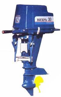
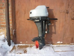
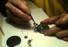
In detail: do-it-yourself repair of a vortex 20 outboard motor from a real master for the site my.housecope.com.
Khorkhordin E.G. Outboard boat motors. Improvement and repair of motors Vikhr, Vikhr-M, Vikhr-30. Directory. - M .: "Publishing House of the Ruchenkin", 2006. - 176 p.
The book systematizes and summarizes the recommendations of many amateur motorboats on self-repair and modernization of the main units and systems of motors. Methods for eliminating the most characteristic shortcomings and malfunctions inherent in Vortex motors of various modifications are considered. The technical characteristics and data on the interchangeability of the most running engine parts are given.
The manual is intended for hobbyists and boaters and outboard motor repair shop workers.
In order to correctly operate your "Whirlwind" and correctly perform preventive and overhaul repairs of the engine, it is necessary to represent the structural differences in the details of the cylinder-piston group "Whirlwind", "Whirlwind-M" and "Whirlwind-30" (taking into account the release time) and when replacing parts to provide the combination of their mating dimensions provided for by the drawings.
The main difference between the engines of the Vortex family motors is in the design of the cylinders.
In the Vortex engine, which has a deflector blowing, the cylinders are separate and each of them is entirely cast from cast iron. The cavities of the purge and outlet channels and the water jacket were formed during casting without additional machining (Fig. 1). According to the diameter of the mirror, the cylinders are divided into three size groups (Table 1). The group number is applied with a shock stamp on the flange of the outlet windows. Such a division into groups within the drawing size (67 +0.03) is necessary for the correct selection of the clearance between the cylinder and the piston.
| Video (click to play). |
In the "Vortex-M" and "-30" engines, both cylinders represent a single block, cast (from an aluminum alloy) with purging and exhaust channels and a water jacket. Blanks for cylinder liners inserted into the block (Fig. 2 and 3) are machined from cast iron castings (cast iron grade SCH21-0). In them, the purge and outlet windows are milled, after which the sleeves are pressed into the bored block and the final processing of the mirror of each cylinder is performed.
The Vortex-M cylinders are divided into the same size groups as those of the Vortex (see Table 1). Since the working volume of the Vortex-30 engine is increased due to the increase in the cylinder diameter, the division into groups is made within the drawing diameter 72 + 0.03 mm (Table 2). The group numbers are applied with an impact stamp opposite each cylinder on the outlet flange or on the block lugs from the side of the outlet ports. The cylinders of the same block can have different group numbers: this means that their diameters are different (within the drawing tolerance) and the pistons must be selected separately for each cylinder.
The Vortex engine cylinders are attached to the crankcase by the flange with six short M8 pins; with pins located on the middle part of the crankcase, both cylinders are simultaneously attached using steel linings.
The Vortex-M cylinder blocks are also attached with six M8 studs, but long ones - passing through the entire block and pulling it together with the crankcase together with the cover.
The Vortex-30 cylinder block is attached to the crankcase with six short M8 pins.
The coordinates of the location of the studs on all models of the motor do not coincide due to the difference in the diameters of the cylinders.
The head block is also cast from an aluminum alloy; it has two combustion chambers with spark plug holes and channels for the passage of cooling water.
The engine head blocks of different models are not interchangeable. In "Vortex" it forms two combustion chambers together with the piston deflector and therefore has a reciprocal depression for it (Fig. 4). Head blocks "Vortex-M" and "-30" are identical in design, but different in connection dimensions due to the difference in cylinder diameters (Fig. 5).
The Vortex head block was produced in two modifications - one-piece (2.111-000) and one with a removable water jacket cover (2.111-700). The split head block consists of body 2.111-004 and cover 2.111-005, which is attached to the body by six screws 3181A6-1 with gasket 2.111-006. The one-piece block of heads is attached to the cylinders with 12 bolts 3017A8-36-18 (M8, length 36 with a thread length of 18 mm), detachable - 12 bolts 3001A8-52-18 (M8, length - 52, thread length - 18).
The Vortex-M head block is secured by six pins extending from the crankcase, and additionally by six short M8 pins screwed into the upper part of the cylinder block.
The Vortex-30 head block is secured with 10 M8 pins screwed into the upper part of the cylinder block. All fasteners are made of steel 30HGSA.
The pistons of engines of all Vortex models are cast from a special aluminum alloy and consist of a head that perceives the pressure of the combustion products and a skirt that guides the movement of the piston in the cylinder.
The piston skirt has ports for the passage of the purge mixture and holes for the piston pin, reinforced from the inside of the piston by nubs-bosses. In the upper part of the skirt, two grooves are made for the two piston seal rings. A steel stopper is installed in each groove to fix the ring in it against longitudinal movement. The place for the stoppers was chosen so that, firstly, the locks of both rings are not located on one straight line (in order to reduce the breakthrough of gases from the combustion chamber) and, secondly, so that the locks do not coincide with the liner windows in order to avoid the ends of the rings falling into windows and their breakage.
Pistons "Vortex" (Fig. 6) and "-M" (Fig. 7) due to the difference in blowing, despite the same diameters, are not interchangeable. Pistons "Vortex-M" and "-30" are identical in design, but different in diameter.
The outer cylindrical surface of the piston skirt has a complex generatrix and is machined according to a copy with control over diameters D1, D2 and D3 (fig. 8), measured at different heights from the edge of the skirt.
Pistons of all models are manufactured with a breakdown by diameter into three groups; the group number is applied with a shock stamp on the piston head. Pistons of all groups are manufactured within the drawing size (tolerance) and are completed with cylinder liners corresponding to the number. The group is determined by diameter D2most important and convenient for measurement.
Pistons "Whirlwind" until 1967 were produced more complete (Table 3) and with a groove width for the piston ring equal to 2.16 + 0.02 mm. In 1967, the clearance between the piston and the cylinder in the zone of the fire belt was increased by reducing the diameters D1 and D2... From the second half of 1968, the groove width was increased to 2.26 + 0.02 mm. The finally accepted breakdown of pistons 2.144-000 into groups is given in table. 4.
Initially, the Vortex-M pistons (4.144-000) were divided into groups by diameter similarly to the Vortex pistons (see Table 4). Then, from October 1971, the coordinate of the D2 measurement was changed from 50 to 49 mm, and the diameters became different (Table 5). Both of these piston modifications (their number is the same) were produced with a groove for a piston ring having a width of 2.0 m, i.e.the grooves had the same width as the grooves of the Vortex piston (2.26 + 0.02). Since December 1971, larger piston rings (2.5 mm) have been used at Vikhr-M, and at the same time the end gap between the ring and the wall of the piston groove has been reduced to 0.1 +0.05 -0,01 pistons with a breakdown into groups according to table. 5 began to be produced with a groove with a width of 2.6 +0.02 and they were assigned No. 4.144-000 / 1.
All pistons for "Vortex-M" are interchangeable only complete with rings. When repairing, it is recommended to give preference to the latest release pistons with widened rings.
The pistons of the Vortex-30 engine (3.144-000) are similar in design to the Vortex-M pistons, but have an increased diameter and width of the groove for the piston ring (2.66 + 0.02 mm). The breakdown of the pistons into groups is given in table. 6; note that the diameter D1, as in the case of Vortex-M, it is measured at a height of 49 mm from the bottom of the skirt.
Vortex pistons of all models are subdivided into three groups also according to the diameter D of the hole for the piston pin (Table 7); the color code of the group is applied from the inside to the piston bosses.
The piston pin is designed to pivot the piston to the connecting rod and transfer force from the piston to the crankshaft. The pin is a short steel tube (fig. 9) that passes through the upper connecting rod head and is installed at the ends in the piston bosses.
When the engine is running, forces act on the piston pin that tend to bend it; the surface of the pin is subject to abrasion against the upper connecting rod head and the piston pin boss. Therefore, a finger made of mild steel is subjected to surface carburizing and quenching to a depth of 0.5-0.8 mm to obtain the required strength and wear resistance.
The finger used in Vortex engines belongs to the so-called floating type - it rotates not only in the upper connecting rod head, but also in the piston bosses. This nearly triples the pin surface area, which reduces wear and pin galling. Pin lubrication holes are made in both the connecting rod top and the piston bosses.
In the axial direction, the floating pin is fixed by two spring retaining rings, installed at its ends in special grooves of the piston bosses. During control inspections of the pistons, it is necessary to ensure the sufficient elasticity of these rings. If you do not pay attention to this, a malfunction of a trifling part can render the cylinder block unusable: when the engine is running, a finger will drop to the cylinder mirror and cut deep (sometimes up to 2-3 mm) irreparable grooves on it.
When selecting a piston pin, a part with a color index corresponding to the index on the piston boss is selected. The color index is applied to the end of the finger.
Piston pins for "Vortex" and "Vortex-M" are identical in geometry and are manufactured with a breakdown by diameter into three size groups. In the first batches of Vortex motors, the finger length was 60 -0.3 mm, and the diameter was 16 ± 0.012 mm, and within the diameter tolerance the fingers were divided into five size groups (Table 8).
Since the beginning of 1967, the tolerance for the diameter of the finger was reduced to 16 ± 0.007, and the fingers of the two extreme groups (blue and yellow indices) were no longer produced; at the same time, the length of the toe was reduced to 59 -0.4 mm. Such a breakdown by diameters is preserved at Vortex even now (Table 9). The same table shows a breakdown into groups and fingers "Vortex-M" and "-30".
As can be seen from the table, the diameters of the Vortex and Vortex-M piston fingers are different - the Vortex fingers are fuller by 0.008 mm. The division of fingers into groups for "Vortex-M" and "-30" is the same, but the length of the fingers of "Vortex-30" is greater and equal to 63.5 -0.3 mm.
Piston rings installed in the grooves on the piston skirt of any two-stroke engine have a double function - they seal the piston in the cylinder, preventing gases from escaping from the working chamber above the piston into the crankcase, and direct the heat flow from the piston head to the cylinder walls and further to the cooling water.In addition, the rings contribute to the uniform distribution of the oil deposited from the fuel mixture entering the crankcase over the cylinder mirror.
Two rings are installed on the pistons of engines of all Vortex models. Piston rings are cast from special cast iron in one piece, but have one cut, called a lock. The end surfaces of the ring are ground. One of the most important properties of a piston ring is its elasticity; its ring should not lose even at those high temperatures at which the piston operates.
In the free state, the gap in the ring joint is usually 5-7 mm. The ring inserted into the cylinder is compressed, the gap in the lock is reduced to 0.2-0.5 mm; due to its elasticity, the ring fits snugly against the cylinder wall, providing the necessary piston seal. The residual, so-called thermal gap in the ring lock is absolutely necessary, since otherwise, when the engine heats up and the ring expands, its ends in the lock will close and the ring will jam in the cylinder.
In the lock, the ends of the ring have a special recess, which includes a locking pin located in the piston groove. As already noted, on the Vortex engines, and initially the Vortex-M engines (see also the Pistons part), which have the same cylinder diameters, thin rings 2.0-0.01 wide were used -0,03 mm (fig. 10).
Later, due to the fact that the "Vortex-M" engine is more forced than the "Vortex" engine, and has a high thermal intensity, in order to increase its motor resource, the width of the ring was increased to 2.5 -0.01 -0,03 mm.
E. N. Semenov, R. V. Strashkevich.
Share this page on social media. networks or add to bookmarks:
Good day everyone! Dear forum users, we need your help! One of these days the motor began to overheat. The water from the exhaust is hot, and the engine loses speed until it comes to a complete stop. After stopping the engine, steam comes out of it and a crackling sound is heard. A drop of water from the cylinders bounces off like a hot iron. I decided to change the impeller. Since the motor will still have to be disassembled, I want to eliminate the problem of water in the gearbox. They say there is some kind of "glass" in the gearbox with bearings instead of a copper-graphite bushing, oil seals and O-rings. Please tell me what it is exactly called so that the store will understand me. There is also a "new sample" plastic pump. Is it really better? And what else do you need to buy? (oil seals, gaskets, what kind of fintiflyushki?) I myself do not understand anything about this, the motor has never been disassembled, so I ask for your help!
No need for a glass with bearings. The sleeve better resists both the blows of the screw and its unbalance.
If there is a sleeve under the pump, this is bad.
But it is impossible to replace, it is necessary to change the gearbox housing.
Tell me, if there is no photo, does your gearbox have another plug, the same as those through which you pour and drain oil into the gearbox?
Start by replacing the impeller, I do not recommend a new plastic one, rubber works great both in the old pump with an oil seal and in a new one without an oil seal. And immediately check the tightness of the water tube at the pump-tube-block connections. If the mirror somehow shakes in the desired position, the hole down should be opposite to the exit up. Check the patency of the water intake channels in the gearbox, assemble the deadwood without a block, stick the spring and hang it in the barrel, twist the spring, the water should rise, or similarly, one gearbox with a key for 10 shaft that comes out of the pump. If it's buzzing, remove the head and see the gasket, maybe under the block. Blowing from below will not give the correct picture, it will blow with a punched gasket. Turn to the luminaries, I've only gone through this five times. Good luck.
Download and read. Then ask questions. If they stay.
Link.
He also has a 6mm diameter steel curve tube that should stand in a deadwood, which is clogged with debris and rust.
If so, then you need to break it, drill a straight duralumin or copper tube under 8mm from above, and unfold the pump with a mirror.
> Tell me, if there is no photo, your gearbox has one more plug,
> the same as those through which the oil in the gearbox
> pouring in, pouring out?
Yes, it seems there are no more traffic jams. Motor from the early 70s.
Disassemble. Take a camera, take a photo, lay it out, ask.
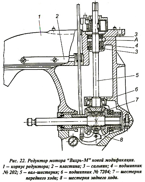
In the picture on the left, an old-style reducer with a copper-graphite bushing, when the bushing is broken, the pump stops pumping water. Poetma was replaced with a bearing. Right with bearing.
Follow the link - about the gearbox.
Link.
First, decide what you have under the pump, bushing or bearing.
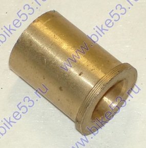
1) In fact, on Vikhr-20, gearboxes with 202 bearings are very rare. In addition, the vortex pump has a very small eccentricity - only a millimeter with a small one. With strong wear of the copper-graphite bushing, normal cooling can no longer be achieved.
2) 2 vehicles: you confuse the propeller shaft glass with a copper-graphite bushing. The bushing cannot be replaced by anything without a major overhaul of the gearbox due to poor lubrication conditions. All attempts to do this with little blood ended in failure. The propeller shaft glass should not be replaced with a bearing one, for reasons described by Yuri.
3) The main place for water to enter the gearbox is the reverse thrust bushing. It is treated, for example, by installing an additional valve stem seal from a Volkswagen.
4) A plastic pump is a complete deception, because of it a good friend B30 ditched this summer. It dies quickly and unpredictably.
5) You need to buy a pump body, an impeller, a mirror and the correct key.
ZY A new gearbox housing with a copper-graphite bushing is lying somewhere. If you need it, write))))
Have not nylon impellers with a metal bushing under the key appeared on sale?
I have simple nylon cranked quickly. If your memory does not fail, the water did not run with such a pomp in neutral.
Bubble67 (Veselyi poselok) wrote:
> If the copper-graphite bushing is heavily worn, it will no longer be possible to cool down properly.
Is it possible to replace this very copper-graphite bushing? Are they on sale? If not, what can be used to replace it?
> You need to buy a pump body, impeller, mirror and the correct
> key.
What is the “correct” key?
> ZY Somewhere lies a new gearbox housing with copper-graphite
> bushing. If you need it - write))))
Duck I live in the Kostroma region, so it will be problematic to ship.
> Have nylon impellers with
> a metal bushing for a key?
Did not met.
> I have simple nylon cranked quickly. If not
> memory fails, in neutral the water did not go with such a pomp.
Absolutely. This is exactly what my friend had. He put such an impeller in the spring, although I diligently dissuaded him. The engine was warming up on XX, and in the middle of the season it cranked at full speed, there was no control, they noticed when the engine slowed down. blackened and stinked. Now the compression has somehow disappeared))) (((
> Is it possible to replace this very copper-graphite bushing? Exists
> Are they on sale? If not, what can be used to replace it?
No, they do not exist. At least, I have not met for a long time. There is nothing to replace, only from the same material. Previously, they sharpened from brushes from the electric train.
> What is the “correct” key?
It looks like a segment from a shaft with a protrusion.
> Duck I live in the Kostroma region, so it will be problematic
> forward.
By mail of the Russian Federation without problems. It's just that I no longer have Vortexes with such a gearbox, but there is a case and a set of gears for it. It's a pity to throw it out, because everything is new, except for the gear shaft.
Purely for life advice to you.
If there is no experience in mechanical assembly work, if you do not understand anything in the drawings, if there is no knowledge of technology, if there are no spare parts for the motor in stock, do not suffer.
Your old B20 carried no better Tohatsu M 18 E2 S or Yamaha 15 FMHS
And if you take a Yamaha 9.9 FMHS and strangle it, you get a Yamaha 15 FMHS, but no technical inspections and registration are needed if you put it on Kazanka, for example.
And you will drive in speed almost the same way.
After all, you will now lay out 20tr for repairs, but there will be little sense.
The engine has already boiled, since “A drop of water from the cylinders bounces off, like from a red-hot iron.”. There are tacks and nafik rings. Whole only a flywheel with square meters, and even then it is not a fact that the middle support square meters with acceptable wear.
Sorry if I said offensively.
rybolub wrote:
> Is it possible to replace this very copper-graphite bushing? Exists
> Are they on sale? If not, what can be used to replace it? Some online stores have it.
> And if you take
> Yamaha ”target =” _blank ”> Link.
> 9.9 FMHS and blow it up, you get Yamaha 15 FMHS, but
> no technical inspections and registration are needed if you put on
> Kazanka, for example.
Exactly! It is much more pleasant to ride on a stifled pit! Slightly weaker, of course, is 20 vortex. But more reliable.
Regarding the repair of Whirlwinds, do not hesitate to write to me in a personal (email address in the profile).
Winter is ahead, you can restore it to a new one even from the ruins.
As for the gearbox, most likely it will be necessary to replace or restore the copper-graphite bushing (how exactly to restore it - see Semyonov-Strashkevich, 1977) and put a new oil seal over it. And also to modify the bushing of the reverse thrust from the standard one, 2 new O-rings will be required. If necessary, I will find the catalog numbers of all the parts in the evening.
At the same time, the reverse thrust can be made detachable, the clutch can be adapted from the "Neptune". Then you will forget about the water in the gearbox.
There is nothing complicated there.
On the engine and overheating. If the CPG really died, and there are no necessary zaps on the B-20, you can turn the B-20 into the B-25 with “little blood” over the winter.
20 tyrov - the amount, IMHO, is overstated. Not so long ago, I restored a completely killed donated “thirty” for about 12 tyrs (in terms of Russian rubles), although at least half of the engine filling had to be changed, and in the gearbox, almost everything that moves. Now he runs more lively than all living things, what the oars look like and where they are, I have completely forgotten. 🙂
If you decide, I will slowly drop Semyonov-Strashkevich to the post office as needed, and I myself know these engines just as well.
Check the integrity of the frame (mount + cores) of the ignition coils. But in general, the principle is the same everywhere: if there is a spark, then there is no gasoline and vice versa))) Good luck!
Ignition is conventional cam. Yesterday I replaced the plugs with wires again. Special boat candles - cheap Soviet candles. Before that, there were imported ones. It seems to work. But the warm one still starts up badly. Hot is ok. but it will stand a little - you have to pull it 15 times.
This weekend I still think I will frolic with him on the river.
And another question. Maybe there are some tips for modernization .. let's put some imported coils .. or a carburetor from something better ..
Have you tried to regulate the carburetor (in the sense of the problem on the hot one)? Fuel level in the float chamber, twist the screws?
Pablo, your description of the problem is too vague. Are the candles (after trying to turn on hot) wet? Is there a spark and what kind? If it is dry and there is a spark, then where is the gasoline (float chamber, b / pump, valve on the hose, if there is one). Well, or a book in hand and off you go. Or see the post above about a foreign car))) Good luck!
I had the same garbage on Neptune-23. As it turned out later, the mixture was over-enriched.
I have had this, I even had a failure of one cylinder for a hot one, i.e. while cold - everything is fine, warmed up - refused. There was always a problem in the ignition, more precisely in the gap between the cams, wire insulation, and so on. IMHO, it is better to replace it with a new one.
a quick start balloon helped not to bother
It seems to me, in this case, the usual thermal shock. After stopping the internal combustion engine, fuel evaporates in the hot carb, and fills the intake tract and cylinders from the float chamber with a closed throttle, causing an over-enrichment of the mixture. You will not believe it turns out that gasoline does not burn! Only gasoline vapors burn, and then in a certain concentration called stoichiometric (correct simplification) about 1 to 15 gasoline
... a-dvs.html
a rich mixture (as well as an extremely lean mixture) cannot be ignited by a spark. The usual method of dealing with this ailment is purging, opening the throttle fully and turning the starter, after about 10-15 strokes, flashes begin and the engine starts. Judging by your posts, you do not have a starter, and it is unlikely to portray a normal blowdown hand-to-hand. By the way, this moment of behavior is typical for all carburetor engines and automobile ones too (excluding the Japs, there is a system that fights this effect)
By the way, about import ..
If an imported motor does not save the sawdust in my head, a spring incident in my life: the first trip to the river, my comrades and I go on motors. We have a cauldron under the 25th served vortex, tovarischa has a new nissamaran with last year's pit. After entering the glide, his yamaha was constantly deaf, after the fifth embarrassment, his launch was taken in tow and dragged away in shame on a whirlwind on a fishing trip, after long digging and proceedings it was found that the seasoned fisherman grossly violated the operating instructions, poured gasoline diluted with oil last year, apparently regretted the good. And although it was stored in an airtight container, it lost its properties. There is only one withdrawal conclusion - I bought an import, listen to the instructions, but our people don't care about it, the installer opens only when the result does not come to the mind of Lazarus, and even then only when, due to a great need, it was necessary ..
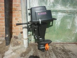
The Whirlwind 20 was once one of the best motors in its category. A special
Among its competitors, it was distinguished by the following advantages:
1. Relatively quiet operation. The model stood out in the segment of domestic outboard motors. Vortex 20 in this parameter could well be compared with foreign counterparts. Thanks to the low noise level, sailing with this unit was especially pleasant.
2. The simple design of the motor made it possible to perform tuning, adjustment, running-in, first start-up, disassembly, maintenance and installation of various elements independently. For lovers of various "lotions" and upgrades, this is a great advantage. Ease of design and operation made the power plant easy to use, even for those who were poorly versed in technology.
3. The main advantage of the Vortex 20 model was its low cost. In comparison with foreign counterparts, the domestic motor was offered at a much more affordable price. The low fuel consumption characteristic of this model also bribed me. This made the unit especially attractive.
4. The long service life made it possible to operate the Vortex 20 for a long time without thinking about the upcoming repairs. Elements with high strength were used in the design of the motor, which significantly extended its service life. The underwater part of the Vortex 20 engine is made of corrosion-resistant materials, so it can be used not only in fresh, but also in salt water. The breakdown was not a big problem for the owner of the motor. Domestic stores have always had a large assortment of parts for this unit. Switches, stickers, tanks, grease, covers, petrol pumps, gearboxes, screws, carburetors and other items were affordable and in stock.
Currently, Vortex 20 is out of production. Nevertheless, today this model is very common among Russian anglers and is widely represented on the used motors market.
Vortex 20 is intended for installation on commercial and tourist boats weighing up to 120 kg and transom height up to 405 mm. The motor can be operated in various bodies of water. The only limitation is the depth (0.8 m). The high power of the unit allows you to tow a water skier and move at a significant speed.
The average fuel consumption for the Vortex 20 outboard motor is 10-11 l / h. The engine is filled with a standard fuel mixture of gasoline (AI-72, AI-80, AI-92) and oil in a ratio of 1:50.Driving with clean gasoline will damage the unit.
The fuel tank of the model holds 22 liters of fuel.
The 2-stroke unit Vortex 20 has a deflector blowing. The model has a forced single-circuit seawater cooling system.
Power plant characteristics:
- working volume - 422 cubic meters cm.;
- rated power - 14.7 (20) kW (hp);
- number of cylinders - 2;
- cylinder diameter - 67 mm;
- compression ratio - 7.
The dry weight of the motor is 48 kg. The model is equipped with a three-blade propeller with a diameter of 240 mm. Control is carried out by a standard tiller.
In most cases, the Vortex 20 engine will not have to be run in, since it is no longer possible to buy a new unit.
However, after a long period of inactivity, experts recommend letting the motor breathe a little by doing the following:
1. Wipe the parts and components of the unit with a clean cloth.
2. If there is preservation oil in the gearbox, it must be drained. After that, you need to fill in fresh oil.
3. Turn the crankshaft with a cord or recoil starter.
4. Install the engine upwards with the plug holes, pour petrol (150-200 g) through the plug hole into each cylinder.
5. Place the unit in working position and turn the crankshaft to drain the cylinder cavity.
6. Flush the fuel tank with gasoline.
7. Dry the candles after flushing them with gasoline and screw them back in.
8. Bring the battery into operation.
There are a lot of reviews about the outboard motor Whirlwind 20. This is explained by the fact that this model is very common in the domestic market.
Stanislav operated the Vortex 20 engine for several years. During the operation, both positive and negative qualities of this unit were revealed. The model is quite heavy. It is very laborious to carry 48 kg alone. Despite the presence of a capture point, picking up Vortex 20 is not easy. It consumes about 10 liters per hour, which is not so much. In this case, the model is content with almost any fuel mixture. This helps a lot, since it is not always possible to get high-quality gasoline and oil in Russia.
For people who are versed in engines, Vortex 20 will be the best option. The unit has a very simple design, but it takes habit here too. I have not experienced any problems with spare parts before. They were available in most stores and were fairly cheap. Recently, however, it has become more difficult to obtain them. Unlike foreign engines, you can literally fix Vortex 20 on your knees. Moreover, the 20-, 25- and 30-strong models are practically the same in design.
I used a motor with a boat "Progress". The load was quite large (gear, tents, backpacks, a lot of food, additional spare parts for the engine, a spare engine and about 300 liters of fuel). It took 14 hours to get there and back. Vortex 20 has withstood such a long journey quite confidently.
Nikolai speaks of the Whirlwind 20 outboard motor with much less enthusiasm. I bought a motor forcibly, because there was not enough money for something more serious. Nowadays it can be called “48 kg of non-ferrous scrap metal”. The quality of the product is just disgusting. I worked without significant problems for about six months, then regular breakdowns began.
Fishing with the Whirlwind 20 is one big problem. The engine periodically stalled and required repair, constantly twitched, sometimes smoked. The candles had to be changed quite often. Often, repair kits were replaced, despite the fact that the equipment was followed very well. The fuel consumption of the model is quite high, therefore it is not very convenient to ride it over long distances. Today it is seriously outdated both in terms of technical characteristics and design.
Among the advantages should be highlighted the low maintenance costs. Spare parts for the Whirlwind 20 motor cost just a penny in comparison with foreign competitors.
At the moment, the production of the Vortex 20 unit has ended, therefore, it will not be possible to purchase a new model.
However, there are quite a few used engine options on the domestic market. Here the cost ranges from 5,000 to 40,000 rubles. Quite cheap offers can lead to much more serious investments.
There are not so many models that can be attributed to analogues of the Whirlwind 20 outboard motor. The main competitor for him is Neptune 2.
If it is necessary to disassemble the motor or its components, it is recommended to disassemble in the following sequence.
When disassembling, remember (it is better to write down) the position of the motor parts before disassembling, especially for small parts, since in some transitions their position is not reflected.
Disassembly should be performed only to the extent required by the purpose of disassembly.
8.10. Disassembly into units
1. Remove the fairing.
2. Disconnect and remove the carburetor throttle actuator rod.
3. Remove the carburetor throttle valve drive shaft.
4. Unscrew the gank and remove the bolt of the reverse link rod, unscrew the rod bushing, remove the pin.
5. Unscrew the screws securing the engine to the deadwood, remove the engine from the deadwood.
6. Remove the gasket from the deadwood. Remove torsion shaft.
7. Unscrew the screws securing the reducer housing to the stern tube, remove the reducer, remove the rubber grommet from the water pump casing, remove the water supply pipe from the stern tube.
8. Unscrew the bolts securing the suspension to the sternwood, remove the retaining plate and rubber gasket, remove the suspension.
Note. Further disassembly of the assemblies should be carried out in accordance with the relevant operations.
8.12. Disassembly of the deadwood
Remove the bracket axle, remove the suspension bracket, latch and gaskets.
8.13. Dismantling the recoil starter
1. Unlock and unscrew the nut, remove the bolt with a bracket.
2. Remove the bracket, spring washer from the bolt. Remove two pawls from the nests of the block.
3. Unfold the starter block by the cord so that the spring is loose.
4. Remove the spring engaging block by turning it clockwise. Remove the block.
ATTENTION! When removing the block from the housing, beware of the coil spring.
8.14. Disassembly of the gearbox
1. Unscrew the screws securing the water pump, remove the pump housing, impeller, pin and plate.
2. Unscrew the upper and lower plugs in the housing and gearbox cover and drain the oil.
3. Unscrew the gearbox cover fixing screws and the rod fixing screw (6, Fig. 4), remove the gearbox cover and the screw shaft with gears and bearings.
4. Remove the bearing cup, shims, gears, shift clutch, bearings from the shaft.
Note. When assembling, place the set of shims in its appropriate place (in thickness).
5. Remove the pinion shaft from the gearbox housing.
6. Rinse all parts in gasoline.
8.15. Disassembly and assembly of the Magdino base with mechanical breakers
Disassembly is carried out in exceptional cases;
a) complete wear of the interrupter textolite pads;
6) complete wear of contacts on the rack or breaker lever:
c) failure of the capacitor.
Disassembly sequence:
1) unscrew the screw nut of the breaker contact post;
2) remove the locking and adjusting washers from the axis;
3) remove the spring breaker lever without touching the connecting screw. The spring has an open groove at the point of attachment with a screw;
4) make the necessary replacement of parts;
5) grease the lever axis with CIATIM-201 GOST 6267-74 grease:
6) the assembly of the interrupting mechanism is carried out in the reverse order;
7) contact mismatch should be within 0.2 mm;
8) the leads of the coils and capacitors must be laid in accordance with the factory release in order to eliminate the possibility of rubbing against the cam or flywheel magnets.
8.16. Assembling the motor
Assemble the motor in the reverse (compared to disassembly) sequence. Before assembling the Cahors or assemblies, rinse all removed parts in clean gasoline and dry. When assembling, lubricate all surfaces of the parts with machine oil.
When setting the flywheel, lubricate the mating surfaces of the cones with MC-20 oil.
When assembling the engine, clean the joint planes of the mating surfaces of the parts from dried sealant and lubricate the planes with fresh bakelite varnish.
Tighten the nuts or bolts gradually, that is, the grinder is tightened to an incomplete effort, then the final tightening is performed.
With a large number of nuts or bolts in flange connections, tightening must be done diagonally, starting from those located in the middle, which will exclude skewing and warping of parts.
When assembling the starter, generously lubricate the spring with technical vaseline.
Be sure to place the previously supplied washers under the starter supports and check that the starter bracket does not reach the ratchet disc. The gap between the starter block and the flywheel is maintained at 7.5 ± 0.5 mm.
Before installing the flywheel on the motor shaft, lay a clean 1.5 mm thick gasket between the contacts of the chopper mechanism in order to prevent breakage of the lever pads.
After installing the flywheel on the motor shaft, remove the gaskets and set the gap between the contacts according to the section "Recommendations for the operation of the motor"
8.17. Instructions for replacing parts.
The internal diameter of the motor cylinders is divided into three groups, respectively, three groups of pistons are made.
| Video (click to play). |
For motors with a power of 25 hp.

