
In detail: do-it-yourself repair of the ZMZ 405 oil pump from a real master for the site my.housecope.com.
Use a screwdriver to bend the antennae of the mesh frame.
... and remove it along with the mesh.
Using the "12" head, unscrew the four bolts.
... and remove the pump inlet.
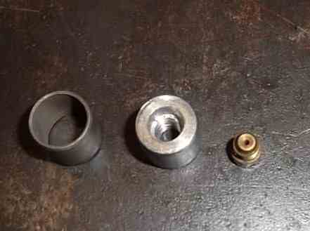
We take out the cotter pin from the hole
... and remove the adjusting washers with a spring from the channel.
... as well as the plunger of the pressure reducing valve.
We assemble the pump in reverse order, lubricating the rubbing parts with engine oil.
After disassembling the engine, we thoroughly clean the parts of carbon deposits, remnants of old gaskets and sealant, rinse with gasoline.
We evaluate the technical condition of engine parts by visual inspection and their micrometer size. We replace damaged or excessively worn engine parts with new ones or repair them.
When repairing a cylinder-piston group, the required clearance between the cylinders and the pistons is ensured by boring and honing the cylinders (at the service station) for previously purchased pistons of the same repair size.
We install the engine block on the stand in an inverted position. Wiping the main bearing beds again with a clean cloth.
... we install liners with a groove and a hole for oil supply in the bed of the main bearings.
On both sides of the middle bed, we put two persistent half rings without protrusions, turning them with transverse grooves to the cheeks of the crankshaft.
Lubricate the liners and main journals of the crankshaft with clean engine oil.
We put the crankshaft in the bed of the cylinder block.
Having installed the liners in the main bearing caps, lubricate them with clean engine oil and place the caps on the crankshaft journals.
| Video (click to play). |
... in accordance with the numbers stamped on them from 1 to 5, starting from the front of the block. The third cover is not labeled.
We insert two persistent half rings with protrusions into its grooves.
We lubricate, we attach the bolts and, turning them evenly, we press the covers into the seats of the cylinder block.
The right and left lid stops have different lengths, so the inverted lid will not fit into the seat.
Tighten the bolts of the main bearing caps to the prescribed torque (see Appendices, p. 325).
We turn the crankshaft by hand. The rotation should be free and even without jamming with little effort. The axial play of the crankshaft must not exceed 0.36 mm.
Otherwise, we check the correctness of the assembly, disassemble and troubleshoot.
We change the oil seal in the rear cover of the cylinder block.
We install the cover with a new gasket in place.
We carry out the selection of piston pins for pistons by size groups. After the finger has been matched to the piston, we select the connecting rod on the finger.
Correctly fitted finger.
... should enter the head under the pressure of the thumb.
... and do not fall out of the connecting rod head when the pin is in the vertical position.
The connecting rods and pistons must be oriented as follows before assembly with the piston pin.
... the protrusion on the lower end of the connecting rod must be on the same side.
as is the word "FRONT" on the outside of the piston boss.
When assembling a piston with a connecting rod, it is necessary to heat the piston to a temperature of 60-80 ° C. Lubricate your finger with engine oil. We introduce the upper connecting rod head between the piston bosses.
... and press the finger into the holes of the piston and connecting rod using a copper hammer or a soft metal mandrel, holding the piston in weight.
After the piston has cooled down, we check the rocking of the connecting rod on the finger, while the finger in the piston bosses should not rotate. We install the retaining rings in the grooves of the piston bosses.
Before installing the piston rings, we select them according to the cylinders.
The compression rings installed in the cylinder to a depth of 20-30 mm should have a gap in the lock of 0.3-0.6 mm, and the oil scraper ring 0.5-1.0 mm.
After installing the piston rings on the pistons, we spread their locks at an angle of 120 ° (approximately) to each other (the joint of the spring expander of the oil scraper ring is located on the side opposite to the ring lock).
We insert new liners into the connecting rod and its cover. We lubricate them, as well as piston rings, cylinder walls and connecting rod journals with clean engine oil.
We put the device on the piston and squeeze the rings, "helping" them to compress by light tapping on the squeeze with the wooden handle of the hammer.
We turn the piston with the inscription "BEFORE" on the boss to the front of the block and insert it into the cylinder, the number of which coincides with the number stamped on the lower head of the connecting rod and its cover.
Tapping through a wooden spacer on the bottom of the piston, we sink it into the cylinder until it stops, controlling the advance of the connecting rod to the crankshaft journal.
Install the connecting rod cover.
The number stamped on the cover must match the connecting rod number and be on the same side. In this case, the projection on the connecting rod cover is directed towards the front of the engine. In the same way, we install the remaining pistons with connecting rods into the block. We tighten the nuts of the connecting rod cap bolts to the prescribed torque (see Appendices, p. 325). We turn the crankshaft by the flywheel. The movement should be smooth, but the force will increase (in comparison with the force of rotation of the "bare" shaft).
Installing the oil pump
Turning the crankshaft, set the mark of the crankshaft sprocket opposite the alignment mark on the cylinder block.
Install the lower chain damper (see "Dismantling the timing mechanism drive", p. 136).
We assemble the oil pump drive (see "Dismantling the oil pump drive", p. 139) by lubricating the drive gears, intermediate shaft bushings and the shaft itself with engine oil.
Before installing, we dip both chains in engine oil.
We put the lower chain on the crankshaft sprocket and the intermediate shaft driven sprocket.
We install the sprocket with a chain on the intermediate shaft in a position at which the alignment marks coincide (the chain on the side of the damper must be tensioned).
We tighten the bolts of the intermediate shaft sprockets and bend the edges of the locking plate; install the axle and lever with an asterisk for the chain tensioner; we put the upper chain on the small sprocket of the intermediate shaft (see "Dismantling the timing mechanism drive", p. 136).
We change the oil seal in the front cover of the block (see "Replacing the front crankshaft oil seal", p. 128) and install the cover with a new gasket and generator bracket. We tighten and tie the upper timing chain to the generator bracket.
We put a new gasket and install the oil pan.
We carry out further assembly of the engine in the reverse order of disassembly.
- Like
- I do not like

- Like
- I do not like
- Like
- I do not like
- Like
- I do not like

rusgg 22 Apr 2012
Pressure 0.5 on hot mechanics.
I do not think that putting two washers under the red.valve is useful. After looking more closely, I discovered that it protects, on the contrary, from excessive oil pressure. Again, I repeat that I am new to GAS.
It is very interesting what kind of reed is used to grind the plate on which there is production from the gears of many.
take any stone
first the piece of iron so that it shines, then the body so that the gears of a silent interference appear
the gears do not wear evenly, which is stronger with the axis (and where it is), therefore it is necessary to adjust the body first for with the axis, then the second gear under the body must be reduced
- Like
- I do not like

Vic123 22 Apr 2012
It is very interesting what kind of reed is used to grind the plate on which there is production from the gears of many.
Yes, an ordinary circle with a sharpener, which is larger.
- Like
- I do not like
take any stone
first the piece of iron so that it shines, then the body so that the gears of a silent interference appear
the gears do not wear evenly, which is stronger with the axis (and where it is), therefore it is necessary to adjust the body first for with the axis, then the second gear under the body must be reduced
As I understand it, the gap between the housing and the gears is better so that it is more than less than the norm.
It’s just that a certain probe (I don’t remember the number) doesn’t fit.
Between the gears themselves and between the plate and the gears, the gap on the probes is normal. There is almost no workout on the plate, the traces are simply visible, they can not even be felt with a fingernail. By the way, it hardly rattles for a shake (washed with gasoline), though I didn’t compare it with a new one.
According to the pictures, no one said whether they should be such badass or not?
And can it really be when assembling a couple of washers on the red.valve? After all, if the pump is working, and then something does not distribute the oil normally through the engine, then the pump will release excess pressure through the valve back. will actually push the oil better, because the excess will be more difficult to give ah?
- Like
- I do not like
rusgg 25 Apr 2012
After all, if the pump is running, and then something does not allow the oil to normally be distributed throughout the engine, then the pump will release excess pressure through the valve backwards. a?
seizures reduce pump performance, by how much? I don’t know
washers adjust the maximum pressure, if the pressure is below 4kg, then the washers do not work
there were no cases of clogging of the oil channel
- Like
- I do not like
seizures reduce pump performance, by how much? I don’t know
washers adjust the maximum pressure, if the pressure is below 4kg, then the washers do not work
there were no cases of clogging of the oil channel
So there won't be any sense from the washers?
Mileage 230000 km, I understand big. Pressure 0.5 on hot. They just say that hydraulic lifters begin to knock at low pressure, but they do not knock!
And changing the oil to a more viscous one significantly raises the pressure? I have 10-40 semi-synthetics.
Post has been editedGAZUS: 25 April 2012 - 21:24
- Like
- I do not like
So there won't be any sense from the washers?
Mileage 230000 km, I understand big. Pressure 0.5 on hot. They just say that hydraulic lifters begin to knock at low pressure, but they do not knock!
And changing the oil to a more viscous one significantly raises the pressure? I have 10-40 semi-synthetics.
I have cars and 500 thousand km each and the pumps are native. On one with a mileage of about 100 thousand, the pump mistakenly changed, disassembled it, the output was decent, they said it was critical, and the pressure was excellent (they were looking for the cause of the noise, it turned out to be the connecting rod bushings) Oil 10w40 comma semi-synthetics.
- Like
- I do not like
I have cars and 500 thousand km each and the pumps are native. On one with a mileage of about 100 thousand, the pump mistakenly changed, disassembled it, the output was decent, they said it was critical, and the pressure was excellent (they were looking for the cause of the noise, it turned out to be the connecting rod bushings) Oil 10w40 comma semi-synthetics.
Eh, where then to look for this pressure!
I understand that 230,000 is not a cause for concern?
- Like
- I do not like
rusgg Apr 26, 2012
So there won't be any sense from the washers?
Mileage 230000 km, I understand big. Pressure 0.5 on hot. They just say that hydraulic lifters begin to knock at low pressure, but they do not knock!
And changing the oil to a more viscous one significantly raises the pressure? I have 10-40 semi-synthetics.
there will be no washers, in general, if you change the pump to a new one and modify it, you raise the pressure by a maximum of 0.5 kg at rpm, nothing will change to xx
and the oil is thick, usually of poor quality, the motor will heat up even lower the pressure will become
try to lower the engine temperature
Post has been editedrusgg: 26 April 2012 - 12:36
- Like
- I do not like
try to lower the engine temperature
Also an idea by the way!
As I understand it, due to the on-fan sensor?
Are there sensors for different temperature conditions at 405.22?
Or is there still a way to lower the temperature of the engine?
Since the light starts blinking when the vent turns on.
- Like
- I do not like
rusgg Apr 26, 2012
Are there sensors for different temperature conditions at 405.22?
Or is there still a way to lower the temperature of the engine?
Since the light starts blinking when the vent turns on.
forced, or oil cooler from gas 66
thermostat at 70, or take it off completely (as I did)
As I understand it, due to the sensor on the fan?
Post has been editedrusgg: 26 April 2012 - 13:11
- Like
- I do not like
forced, or oil cooler from gas 66
thermostat at 70, or take it off completely (as I did)
My oil cooler is already drowned out.
And what about a 70-degree thermostat or a size? I'm not really fumbling in this engine yet.
- Like
- I do not like
rusgg Apr 26, 2012
My oil cooler is already drowned out.
And what about a 70-degree thermostat or a size? I'm not really fumbling in this engine yet.
70 degrees, throw it off completely better, and put it on in winter
you just need to plug the bottom hole in the thermostat housing
the oil cooler needs to be turned on, but not the one that is installed at the factory, it needs to cool the oil
wash the engine, all
Post has been editedrusgg: 26 April 2012 - 13:24
- Like
- I do not like
rusgg Apr 26, 2012
I had such that gasoline got into the oil, it looks like the filter did not hold the oil, it flowed into the crankcase when it muffled
gasoline did not flow in a stream, dripped quietly.
the oil turned gray quickly and the pressure was lost
- Like
- I do not like
70 degrees, throw it off completely better, and in winter put it on
you just need to plug the bottom hole in the thermostat housing
the oil cooler needs to be turned on, but not the one that is installed at the factory, it needs to cool the oil
wash the engine, all
I had such that gasoline got into the oil, it looks like the filter did not hold the oil, it flowed into the crankcase when it muffled
gasoline did not flow in a stream, dripped quietly.
the oil turned gray quickly and the pressure was lost
No, there is definitely no gasoline. I merged clean oil, the good darkened only a little (the engine did not work much after repairs (timing, hydraulic lifters)). The engine itself was cleaned and washed during repairs.
About GAZ 66 If my friends had a radiator, I would try it. There is no money for experiments. Maybe in the future.
Is sensor 82-87 not enough? I have 92 grams on it.
- Like
- I do not like
rusgg Apr 26, 2012
Is sensor 82-87 not enough? I have 92 grams on it.
the effect will be, only the fan motor would take out
but you need the thermos to be below 82 degrees
- Like
- I do not like
the effect will be, only the fan motor would take out
but you need the thermos to be below 82 degrees
Does this mean that any thermostat needs to be changed or is there a separate sensor?
It's just that if the thermostat is sad, I just put everything back together.
Muzzle> antifreeze> radiator> electrical coupling> thermostat.
- Like
- I do not like
rusgg Apr 26, 2012
Does this mean that any thermostat needs to be changed or is there a separate sensor?
It's just that if the thermostat is sad https://my.housecope.com/wp-content/uploads/ext/3317/forum/public/s. , only collected everything back.
Muzzle> antifreeze> radiator> electrical coupling> thermostat. https://my.housecope.com/wp-content/uploads/ext/3317/forum/public/s.
how difficult it is for you, my thermostat cover can be removed separately, well, the antifreeze must be drained of course
15. Flush the pump parts with gasoline and blow with compressed air.
16. If there is a wear from the gears on the intermediate plate, the plate must be sanded so that no traces of wear are left.
If it is badly worn, replace the pump.
18. Check the ease of rotation of the gears in the pump housing.
They should rotate freely.
19. Check the ease of movement of the relief valve plug in the body.
It should move freely.
20. Clean off dirt and rinse the oil receiver mesh with white spirit.
If the mesh cannot be cleaned or is damaged, replace it.
25. Replace worn or damaged parts. Observing maximum cleanliness during assembly, reassemble the pump in the reverse order of disassembly.
26. Install the parts in the reverse order of removal. Fill the engine with oil.
GAZ Sobol Malysh ›Logbook› 3.Intermediate repair of the oil pump or how to increase the oil pressure by 406
Earlier, I already skipped posts on how to increase the oil pressure in the ZMZ 406.
I saw a long time ago, in the vastness of the vast web, an increase in pressure by modifying the oil pump.
I don’t take authorship on myself! I am only writing about the method itself.
In the video, I told in detail what and how you need to do with this miracle of machine production, we are looking.
Good day everyone. In today's article we are considering a typical problem - the oil pressure in the ZMZ 406 engine has disappeared. Unfortunately, this is a fairly common problem and there are quite a few typical reasons in the article, we will analyze all the reasons and how they manifest themselves.
Let's start with a description of the design of the ZMZ 406 lubrication system:
The oil pump is driven from the intermediate shaft through a hexagon. The oil pump has a pressure reducing valve that relieves excess oil pressure back into the crankcase. From the oil pump, oil is fed through a filter to the main oil line, from which the crankshaft journals and the intermediate shaft bushings of the timing drive are lubricated. Also from the main highway there is a channel to the cylinder head and to the hydraulic tensioners. In the cylinder head, in turn, 2 oil channels are drilled parallel to the camshafts. These channels supply oil to each camshaft journal and to each of the 16 hydraulic lifters.
The most problematic places in the lubrication system are the pressure reducing valve, intermediate shaft bushings and hydraulic chain tensioners, but first things first ...
There are only two reasons in this case - the oil pump pressure relief valve is stuck in the open position. It looks like this:
This usually happens due to dirt getting under the pressure reducing valve. Even the smallest crumb wedges the valve and it does not close completely.
The second typical reason is a breakdown of the oil pump drive.
It should be noted that these two malfunctions are extremely rare and occur when the oil change interval is not observed and when operating on oil that does not correspond to the climate.
This is the most common problem associated with normal wear and tear, periodic maintenance and design errors.….
The most common reason is the oil filter.
During the operation of the gazelle (2705), I changed the filter every 5000 km, and changed the oil every 10,000 km. The reason is that when operating on gasoline, the oil quickly darkens and a heap of dirt forms in it that clogs the filter. When operating on gas, this problem is not observed!
The second most popular reason is the ingress of gasoline into fuel.
Basically, the proportion of carburetor versions of the 406 engine is fair (when the gasoline pump membrane breaks, gasoline inevitably enters the oil), but on an injection engine with a running nozzle, this is a quite possible scenario.
The third reason is wear and tear.
Due to wear, all the gaps in the friction pairs gradually increase.
- The main place where pressure is lost is the intermediate shaft. Many do not change the intermediate shaft support bushings even during a major overhaul, but it is in these bushings that most of the pressure is lost.
- The second most popular place is the worn out hydraulic chain tensioners.
- Third place is cylinder head wear and camshaft wear.The fact is that on the 406 engine, the camshaft beds are located in the body of the cylinder head and at the slightest "drift" of the plane, the wear of the bed increases significantly - the result is a pressure loss. With the wear of the shaft itself, the clearance in the friction pair increases and the pressure is also lost.
- The fourth place is the wear of the oil pump. When worn, the pump will not pump enough oil into the engine lubrication system and there will be no oil pressure. You can deal with this by rebuilding the pump with the output of its planes or replacing the oil pump assembly with an oil pump from ZMZ 514 (it is for a diesel engine and has increased performance).
- Fifth place - hydraulic compensators for valve clearances, expansion joints in the cylinder head 16 (according to the number of valves) and with high mileage, their beds are also subject to wear, but the service life of the beds of the compensators, as a rule, exceeds the service life of the cylinder head.
The fourth reason is the oil bypass valve springs.
A bypass valve is installed on the oil pump housing, it opens at high oil pressure. The fact is that over time, the valve springs weaken and some of the oil pressure is lost on this valve. It's okay if you place a couple of washers under the valve spring when overhauling the pump.
On some modifications of the ZMZ 406, a radiator for cooling the oil is installed, but in fact this design is practically not used since it reduces the pressure of the already liquefied oil and has low-quality taps that are constantly running. Relatively competently, the oil cooler is implemented at ZMZ 405 (a thermal valve is used), but even there its effectiveness is questionable. In most cases, it is advisable to muffle the oil cooler and use a more thermostable oil (tested on personal experience with gas 2705 with a mileage of 470,000 km).
- More frequent oil filter replacement.
- Replacing the oil pump with a pump from ZMZ 514, part number 514 .1011010
- Disconnecting the oil cooler or replacing it with a heat exchanger.
- Replacing the oil with a thicker and higher quality one, it is the viscosity at high temperatures that is important.
- Placing 2-3 washers under the oil bypass valve spring
This is more groundwork for the future ... I recommend. Do this at the bulkhead.
Be sure to reverse the countershaft and turn the bushings correctly.
Install the jets in the lubrication system.
The fact is that there are several places in the engine where a lot of pressure is lost, and in order to increase the engine's service life during a major overhaul, it makes sense to plug some channels in the lubrication system with carburetor jets! The best option turned out to be jets reamed with a 2 mm drill.
So, here are these places and options for their jetting:
Oil pump shaft lubrication hole
Hydraulic chain tensioners (upper and lower)
That's all for me. I hope that the problem of missing oil pressure in the 406 engine will never bother you again.
The last way to raise oil pressure on these engines, provided that the main loss was in the cylinder head. The method is quite radical and requires serious financial investments. All previous videos show emergency options for increasing oil pressure, in situations where there is no way to get up somewhere for repairs (the first video or at the moment there are financial difficulties to buy a new block head (second video and third video
The plans are to shoot videos about raising the pressure by reducing the diameter of the outlet holes of the oil channels in the cylinder block. Will be theoretical or directly showing the process, I do not know, the project on the engine is suspended at the moment.
Site:
Machine page:
Video A way to raise the oil pressure ZMZ 406 405 409 (Radical) channel Dmitry Efimov
The Gazelle 405 engine is an improved ZMZ-40522.10 engine, which mainly reduced the Euro 3 toxicity and increased reliability and service life.
The ZMZ-405 was also installed on trucks weighing up to 3500 kg.
The motors are designed for operation in climatic version "U2" in a temperate climate, i.e.at temperatures from -45 to + 40 degrees and humidity up to 100% at + 25 degrees.
Repair of the gazelle 405 engine begins with the removal of the engine from the car and its further disassembly.
If, while repairing the 405 gazelle engine, holes were found on the cylinder head on the cylinder walls, with cracks on the upper surface and on the ribs that support the main bearings, with holes on the jacket and crankcase, everything must be replaced with new ones.
As a result of wear, the cylinders in the cylinder head become along the length of an irregular cone, and around the circumference - an oval. The greatest wear occurs in the upper part of the cylinders against the upper compression ring, when the piston is in TDC, and the least wear occurs in the lower part, when the piston is in BDC.
When repairing the gazelle 405 engine, all cylinders in one block are adjusted to one repair size with a tolerance of + 0.036 ... + 0.072 mm from the norm. An exception is when it is necessary to remove shallow scratches on the cylinder mirror (by 0.10 mm), here only defective cylinders can be corrected.
In cases where only a limited number of pistons are available, it is recommended to calculate the nominal diameter for each cylinder based on the actual size of the piston skirt diameter intended for the given cylinder, and to machine the cylinders with the machining tolerance specified below.
Deviations from the geometrically correct shape of the cylinders should be located in the tolerance field of the dimensional group for the cylinder diameter.
Often, repairs include replacing the bushings of the countershaft bearings with standard or repair ones, of increased thickness, depending on the wear of the bore holes in the cylinder block, and subsequent boring of the inner bore of the bushings to a standard or overhaul size, depending on the wear of the countershaft bearing journals. The repair sleeves are made of an antifriction alloy (see Figure 7).
Replace standard bushings with repair ones also when they are loose or turned.
Remove the tube before installing the intermediate shaft supports. When installing the repair sleeves, make sure that the holes of the oil channels are aligned. To make boring of intermediate shaft supports in one installation. Press in the tube with anaerobic sealant.
If the intermediate shaft journals are worn out, then "grind" them under the repair size.
If the holes for the oil pump drive have worn out more than the allowable one, then the holes must be bored to the repair size for the repair bushings. The repair sleeves are made of gray cast iron with an outer diameter of 21 mm and a length: lower - 17 mm, upper - 30 mm.
Press in the repair sleeves, drill through the hole with tapered thread in the upper sleeve a through hole for the oil supply Ø 3.5 mm, entering the oil line of the cylinder block, and machine the holes in the sleeves to the nominal size. The machining of the cylinder block bore holes for bushings and bushing bores should be performed in one installation.
We remove the drive of the gas distribution mechanism (see Dismantling the drive of the gas distribution mechanism). If at the same time the cylinder head was not removed, remove the intake manifold (see Removing the intake manifold).
Using a 12 key, unscrew the two bolts securing the intermediate shaft flange and remove the flange.
We screw two bolts (M8) into the threaded holes of the intermediate shaft end.
Using a 12 key, unscrew the nut securing the intermediate shaft gear, rotating the shaft with a screwdriver inserted between the bolts.
We take out the intermediate shaft from the block ...
... and a hexagonal drive shaft.
We assemble the drive in reverse order. We recommend installing the hexagonal drive shaft last.
The condition of the oil pump of the ZMZ-409 engine can be most fully assessed by checking it on a special stand. With low pressure in the lubrication system, a possible cause of which could be a malfunction of the oil pump, the pump must be disassembled and the technical condition of its parts must be checked.
Checking the condition and repair of the oil pump of the ZMZ-409 engine, clearances and dimensions of parts, the procedure for disassembling and assembling the oil pump.
When checking the pressure relief valve of the oil pump of the ZMZ-409 engine, make sure that its plunger moves in the opening of the inlet pipe freely, without jamming, and the spring is in good condition. Check for defects on the working surface of the plunger and the hole in the intake pipe of the oil pump, which can lead to a drop in pressure in the lubrication system and seizure of the plunger.
If necessary, remove small defects in the surface of the inlet opening by grinding with a fine-grained sandpaper, avoiding an increase in the diameter. Wear of the inlet opening for a plunger over a size of 13.1 mm in diameter and a plunger less than an outside diameter of 12.92 mm is not allowed.
Check for spring looseness. The spring length of the pressure reducing valve must be 50 mm in free position. The compression force of the spring to a length of 40 mm should be 45 N + - 2.94 N (4.6 kgf + - 0.3 kgf). With less force, the spring is subject to rejection.
If on the plane of the baffle of the oil pump of the ZMZ-409 engine there is a significant depletion from the gears, it is necessary to grind it until the traces of the depletion are eliminated, but to a size of the partition height of at least 5.8 mm.
In case of significant wear of the oil pump housing of the ZMZ-409 engine, its gears, axle pressed into the pump housing and other parts, the worn out part or the oil pump assembly should be replaced.
Dimensions and clearances of the mating parts of the oil pump, pressure reducing valve and oil pump drive of the ZMZ-409 engine.
- Bend back the whiskers of the mesh frame, remove the frame and mesh.
- Unscrew the three screws, remove the inlet and the bulkhead.
- Remove the driven gear and the drive pinion shaft assembly from the housing.
- Remove the washer, spring and plunger of the pressure reducing valve from the inlet pipe after removing the cotter pin.
- Rinse the parts and blow with compressed air.
- Install the plunger, spring, washer of the pressure reducing valve into the hole in the inlet and secure with a split pin. The washer should be installed, removed when disassembling the pump, as it is an adjusting one.
- Install the roller assembly with the pinion gear into the oil pump housing and check that it rotates easily.
- Install the driven gear in the housing and check the ease of rotation of both gears.
- Install the bulkhead, inlet and screw it to the body with three screws and washers.
- Install the mesh, mesh frame and roll the frame mustache onto the edges of the oil pump receptacle.
Before proceeding with disassembly, you should determine the modification and diagnose the engine. It will scan the electronic system of control units and show what defects and malfunctions are present. If it is not possible to determine the cause of the malfunction using diagnostics, then you cannot do without disassembling the engine.
How to determine whether the ZMZ-405 engine needs repair at all or not? To do this, the head of the block and the block itself should be tested for tightness. The press method will do. The holes are tightly sealed with pads or rubber seals. Then air is blown in under pressure.
Repair begins with the removal and subsequent disassembly of the engine. In order to remove the jerking of the motor, you need to set a certain clearance in the valves. Replacing spark plugs is indispensable.
If, in the process of disassembling the engine, scuffs, cracks or dents on the walls of the engine cylinders are found, then they will have to be replaced with new ones. It should be taken into account, that all cylinders of one block should be fitted to the same size... The permissible size deviation should be no more than 0.036 - 0.072 from the norm.
Very often, repairing the ZMZ-405 engine involves replacing the intermediate shaft bushings with increased thickness. If the journals of the intermediate shaft of the engine are worn out, then they can be slightly sanded to the repair size. The holes for the pump drive can be repaired by boring them to repair size.
To increase the reliability and dynamism, you can tune the ZMZ-405 engine. To do this, replace the bushing on the upper head with a thicker one, for example from a Mercedes. You will feel the difference immediately.
An important and very responsible one is the repair of the 405 cylinder head of the engine. Correctly repaired head means 70% of accurate and well-coordinated engine performance... That is why the head repair is of great importance.


