
In detail: do-it-yourself mixing console repair from a real master for the site my.housecope.com.
Repair of mixing consoles and its cost depends on the type of the device itself, the complexity of the failed unit or element and the quality of the new spare part. The remote control itself is an electronic device that is designed to mix different numbers of sound signals. At the same time, they can be summed up into one or several separate audio tracks, and are used in the areas of sound recording, playback, as well as television and radio broadcasting.
The main difference between this equipment, for connecting several audio channels into one, is on the basis of which radio components and on what principle the mixer works. They are divided into:
- Analog, when the sound signal is an electrical impulse of one size or another;
- Digital. The sound is converted to a digital signal, so it is less prone to distortion and interference.
The following difference is expressed in the number of inputs and outputs, for example, modern professional mixing consoles used in concerts and in recording studios consist of:
- from 32 entrances;
- at least 6 Aux-buses;
- wide-band equalizer, consisting of several dozen precise and sensitive faders;
A fader is a modern analogue of a conventional slide resistor, by the way, this element is almost the main control element of a mixing console. Some are equipped with miniature motors that drive a fader knob to give the plant operator a visualization of the signal level. Every second repair of mixing consoles is reduced to replacing one or more of these elements to restore the full functionality of the device. But this does not mean that the owners of compact and budget mixers with a small number of processed channels and potentiometers of a simple design, instead of fades, fail less often. The likelihood of a malfunction depends on the mode of operation and the manufacturer of this device, each part included in its composition and the humidity in which the device operates.
| Video (click to play). |
There is a separate class of mixing consoles in the world of music that can be used in the work of a DJ. They consist of fewer channels, but are equipped with:
- a special device for smooth mixing of input signals - a crossfader;
- a block that creates special sound effects that a DJ cannot do without.
Knowing how the mixer works and what it consists of, the repairman of this equipment plans to search for a malfunction. They have input and output sections of audio signals: mono and stereo and a multiple of the input channels.
The main elements of the inlet section:
- Preamplifier. It is equipped with precise sensitivity adjustment, which allows you to set the desired operating level of the input signal;
- The constant current source required for condenser microphones to operate is called phantom power;
- Equalizer, consisting of many bands, their number makes it possible to more carefully and accurately adjust the frequency response of the incoming signal;
- Routing unit for processing by the built-in or external processor of sound effects, as well as sending a signal to a separate observation line and a visual picture;
- Pan control that forms the sound picture;
- Volume control or fader for each of the input channels separately.
And these are the constituent elements of only the input section of the signals, in turn, the output is a control system, as well as the redirection of signals received from the input section.
Among the most common problems with all types of mixers, there are three main ones:
- Malfunctioning knobs, potentiometers or faders. This is expressed in the breakage or disappearance of the signal during the movement or movement of the handle;
- Power supply malfunctions. They are mainly related to the power supply system and its stabilization. Some mixers are equipped with built-in effective stabilizing devices that allow operation even with deviations from the mains voltage of + -50 Volts.
- Connector problems. They appear from frequent and careless use, connection of low-quality cords and connectors with different dimensions.
Based on the foregoing, it can be seen that the repair of mixing consoles is a special type of work that only professionals can perform.
__________________
Philip Newell commanded to share knowledge
For letters and newspapers [Links only visible to registered users. ]
Main unit: PS Solo + NAG QM-400, Wharfedale Pro EVP-X 12 + Synq 1k0, Yamaha MG 12/4 FX, ProAudio WS 810 HT. Subwoofers EuroSound XF-12 + EuroSound XZ-800, LMS EuroSound EX 2040
Backup EVM BS 123 + Park Audio II VX-700-4, Yamaha MG 124 CX.
PS Luina F8 HD + 15 Sub, TDA Calex 4 + 12 ″ Sub (exploiting)
For connoisseurs of Vermona L 9064 + Vermona Regent 1010, Vermona M-310, PM-01 Electronics 
__________________
Who likes watermelon and who likes pork cartilage
[Links only visible to registered users. ]
not selling sub speaker Beyma 15G450N
Namesake, will this help me from the link?
[Links only visible to registered users. ]
__________________
Who likes watermelon and who likes pork cartilage
[Links only visible to registered users. ]
not selling sub speaker Beyma 15G450N
Yes. If the conductive layer of the fader is not worn out to the point of holes, but rather heavily soiled, i.e. there are crackles and signal interruptions when it is moved, flushing with this Contact will help. The same is the case with sticky, crunchy, popping signal routing buttons. It is important before using this tool to blow out the remote control with a vacuum cleaner to remove accumulated dust, then, following the instructions for Contact, spray the agent through the standard sprayer as close as possible to the working gap of the fader (potentiometer), push-button contact, etc. After the agent is introduced, the treated regulator it should be smoothly worked several times (15-20) along the entire length of the working stroke. Connect to the network no earlier than 3-4 hours after spray treatment. The product must not be used to treat energized equipment.
In some cases, due to its high penetrating power, it even helps with sealed potentiometers. The effect is given even when processing vintage, fairly neglected equipment.
And it also very well helps with the "clogging" of the contact surfaces of the on-board electrical equipment of cars. Relays, ignition locks, starters, etc.
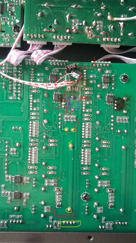
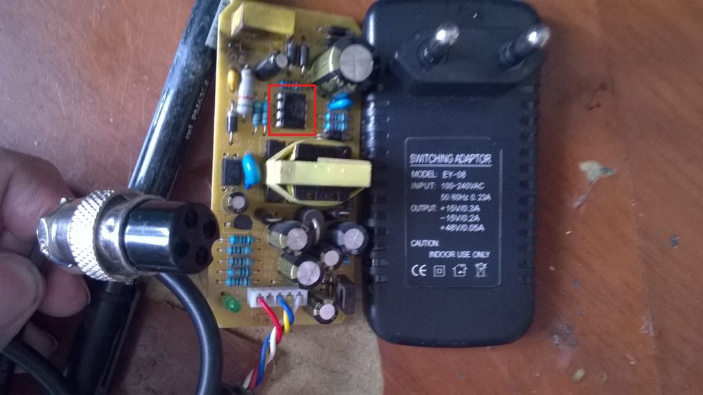
They brought a power supply unit, or rather, even with a mixing console, the problem is that there is a sharp background in all channels of the console. I connected the power supply, listened - really phonit! I started with the power supply, it is made in a sturdy case with a protective ventilation system, with beautiful stickers - we open it and see that everything is not so expensive inside, the board darkened in order, overheating on the face, we check the capacitors on the output - here there is a bipolar 15 volt for shoulder, but with a little current on the load. So, after checking the output capacitors, there were several that had an increased ESR value, and the voltage drop was above normal, the capacitance was slightly less than the specified value, there were no such capacitors, therefore, I put 1,000 microfarads instead of 470 microfarads. I thought that this would solve the problem and filtering would get better, but the problem was only partially gone.
I looked and looked at the printed circuit board, and could not understand: what else is wrong here.I decided to solder well, since there were many types of rings from prolonged overheating, so I soldered, but even then the problem did not dare, then I decided to wash the board - I took an expensive degreaser and began to wash it all over the board, and noticed that under the network capacitor in the filter on the hot part of the block some kind of dirt flowed, poked it in the side with a screwdriver and it became clear that it was urgent to solder it - I took it off and saw that one of the conclusions had simply been driven off by time and leaking electrolyte, and thus there was practically no capacity after the rectifier at the unit!
After looking for a similar one, I did not find it and put the capacity at 10 microfarads 400 V, connected it - the problem was solved - a crystal sound and no noise and backgrounds, the device worked as it should. The disadvantages of the power supply are that when disassembling, in order to remove the board, you have to unsolder the three-pin connector to the power cord, and with a careless movement you can break off a part of the case. It is already easier to assemble, sealing and assembly is much easier when you already understand what and where it is worth. As a result, everything works - both the power supply unit and, of course, the mixing console.
 Xedg22 28 January 2014 - 12:21
 Xedg22 28 January 2014 - 12:21
Buying a good mixer is expensive. So I thought I might assemble it myself. There is not a lot of hem in the net, and there is no suitable one.
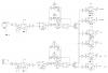
Throw here the diagrams of the mixers, and who did it yourself, please describe what pitfalls you encountered.
Thanks in advance.
I would like something with 2-3-microphone inputs 4-5-line
Nazarett 28 January 2014 - 12:42
Diamontius 28 January 2014 - 13:18
Xedg22 28 January 2014 - 13:32
Nazarett, yes, but not with a timbre block.
Diamontius, I'll take note of a good scheme.
What transistors did you use?
Diamontius 28 January 2014 - 13:47
What transistors did you use?
[/ quote]
In the microphone part, it is desirable to be quieter (less noise) and the corresponding KU (100-500 is enough). In terms of the adder, they are similar, but the KU can be smaller, in my case C3198 in the adder, KT3102 in the microphone preamp. Resistors "Balance" are better to take less - 3K-10K.
Nazarett 28 January 2014 - 14:00
Do you need TB for each channel?
Then it is easier to use op-amps quadruple or double
Xedg22 28 January 2014 - 15:23
SeRpaQ :-) 28 January 2014 - 15:45
Xedg22 28 January 2014 - 16:10
SeRpaQ :-) 28 January 2014 - 16:38
Well, actually. If you have any questions, please contact us!
I saw the jamb as soon as I laid it out) remember in places the nests, from the bottom of the HLR on top of the jack, just the inputs, without strapping, well, or the resistances R1 and R65, change places, everything else is normal
Diamontius 28 January 2014 - 16:47
SeRpaQ :-) 28 January 2014 - 16:49
Diamontius (28 January 2014 - 16:47) wrote:
Diamontius 28 January 2014 - 17:06
SeRpaQ :-) 28 January 2014 - 17:20
steeler 28 January 2014 - 17:54
HeiZe 28 January 2014 - 18:23
Diamontius 28 January 2014 - 18:53
ttgr 28 January 2014 - 20:04
Halvalife 29 January 2014 - 19:09
Kira 29 January 2014 - 22:40
RemiX 31 January 2014 - 11:19
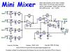
I would like to offer you a preamp circuit for a mixer that is very easy to manufacture with a minimum of parts and does not actually need to be set up before launch. The repeatability is literally 100%. Moreover, this preamplifier is both conventional and balanced; and, if desired, if a potential of +48 volts is applied to the inputs, then it is also phantom! Meet: 
PS: I have already collected 16 of these - for the role of a rack interface for the MAudio 1010LT sound card
Stah Lynx 31 January 2014 - 17:05
HeiZe 01 February 2014 - 07:39
Welder February 27, 2014 - 10:09
Would recommend looking towards Mackie mixers. There is a very correct mic preamp. Making a balanced input to an op-amp is not entirely correct if specialized microcircuits are not used.
A good mixer should contain flexible controls for the frequency response of each channel and reverbs, preferably compression for each channel, a master compressor for the mixed signal and a functional graphic equalizer, plus the necessary switching. This is if the mixer is intended for comfortable studio work or for live performances.
I remember ten years ago we were recording through a four-channel mixer with five transistors into a proton tape recorder. It was so exciting for us then. Then a Beringer mixer with a built-in processor appeared and we just pissed ourselves on boiling water.Over time, it became clear that the beringer is still shit, and for several years I have been hatching the idea of creating my own remote control, but I have not yet given birth to a finished device.
sanyaretro 25 August 2017 - 22:00
RemiX (31 January 2014 - 11:19) wrote:
I would like to offer you a preamp circuit for a mixer that is very easy to manufacture with a minimum of parts and does not actually need to be set up before launch. The repeatability is literally 100%. Moreover, this preamplifier is both conventional and balanced; and, if desired, if a potential of +48 volts is applied to the inputs, then it is also phantom! Meet:
PS: I have already collected 16 of these - for the role of a rack interface for the MAudio 1010LT sound card
If you are engaged in holding weddings, banquets and other party events, then with a probability of 99% you will use a mixing console + active / passive acoustic systems, as well as radio microphones in your work. Mixing consoles, as part of the audio path, are equipped with mechanical level and volume controls - they often break. In such cases, you need to repair mixing consoles in Ryazan or the Ryazan region.
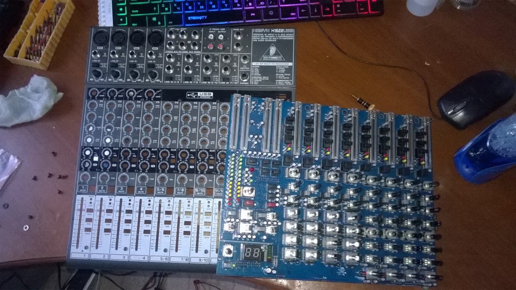
I am engaged in the repair of sound and light equipment as well as repairing electric guitars for over 5 years in Ryazan. Over the years of my repairs and refurbishment of audio equipment and especially mixing consoles, the most common problems are fader problems. This malfunction of the mixing console is solved by replacing the slide resistor (fader).
The most common faults in mixing consoles are mechanical damage or wear of conductive tracks on the volume controls of the input and output channels. It often happens that the mixing console is completely flooded with liquids from the banquet: alcohol, juices, water, cocktails, or worse.
Filling with liquids is a rather sad defect, as in the case of any electronics, you have to completely solder the board and disassemble all the volume controls to the screw.
Malfunctions of mixing consoles in Ryazan
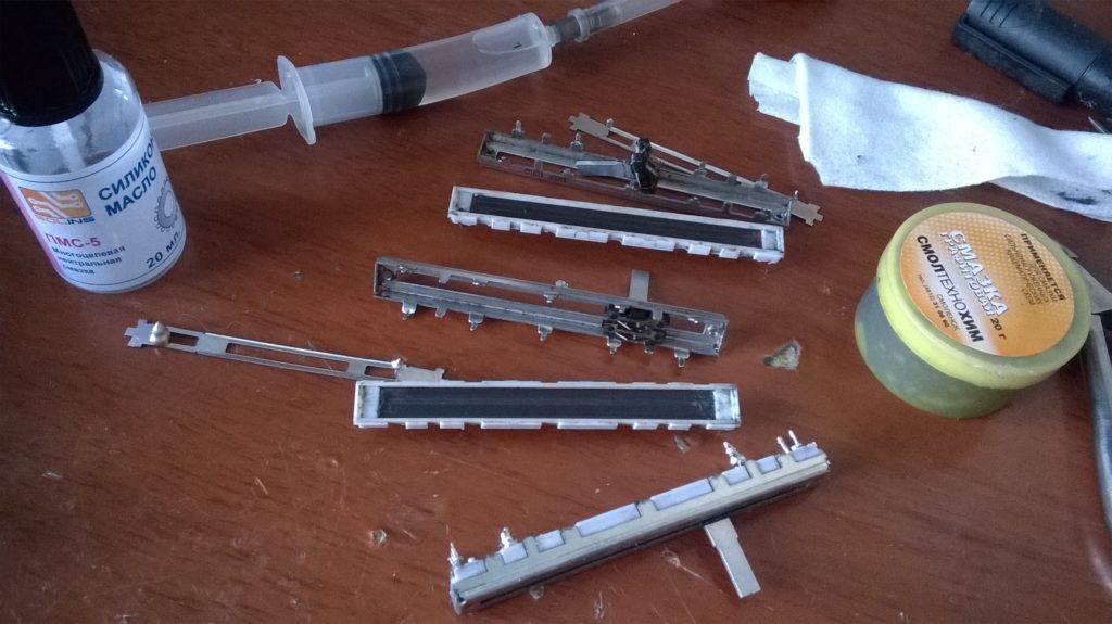
Firstly, you can temporarily revive the fader itself - by dropping it with technical oil or splashing silicone on the graphite track, that is, inside. Or pre-wash all the insides with alcohol, sprinkling so much from a syringe so that it flows in. Then dry and add grease. The problem with this method is that after some time the defect will return and may lead to a complete failure of the fader to work. On the faders of the output channels, this is critical for the complete loss of signal, left or right.
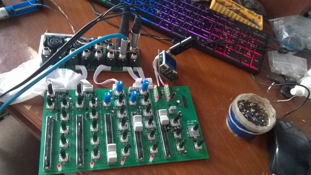
- The mixing console is disassembled;
- A fader that does not work is soldered (better all at once);
- Disassemble the fader carefully following the logic;
- The oxide of the contacts of the variable engine is removed, as a rule it is dust and dirt with the remnants of the graphic layer. Contacts should be carefully cleaned with a file or blade, until they shine;
- The graphite track is lubricated with conductive graphite grease or the softest pencil, in the case of a pencil - with a bold layer sparing no graphite, without closing the tracks;
- Assemble the fader back, solder it back into the seats as carefully as possible, after checking the contact resistance with a tester.
Mixer fader repair 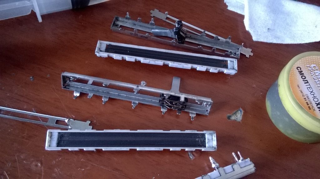 how to clean mixer faders
If everything works and you haven't broken anything, you can write yourself a medal! And be proud to rank yourself among the rare caste of straight-handed people. Most people don't even know how to change a burnt out light bulb or solder 2 wires.
Replacing Mixer Faders
This malfunction is common in Behringer consoles. The defect manifests itself in the form of clicks, crackles or incomprehensible overtones in the sound path as the mixing console warms up (half an hour - an hour of work). This malfunction of the mixing console is treated by soldering and replacing all electrolytic capacitors on the effects processor board and nearby ones responsible for signal circuits.
Often there is a complete burnout of the effects processor of the mixing console, this defect is more problematic in the treatment. Behringer, Yamaha, Peavey, Soundcraft and other players in the audio equipment market sacredly respect the capitalist traditionbased on the fact that, parts are not sold to the end consumer - provide only a full-fledged repair for a horse price tag. This attitude towards the consumer I really don't like it, but askal of capitalism who, in any incomprehensible situation, tries to warm up his buyer - freezes not only me, but de facto is the world standard.
Potirany about how I see this situation:
- You are the end customer, an ordinary user of the handshake, a priori you do not know how to do anything and do not read the instructions, you confuse the left and right channels. We will not sell you any spare parts, you will break everything, bring them to our official service center, which is one for the whole country in the city of MAASKVA or St. Petersburg, our specialists will do everything (yesterday's PTUs with soldering irons). Diagnostics $ 50, repair $ 100, spare parts $ 50 + VAT from you $ 250 for repairing the mixing console, we wait for spare parts 3 weeks + your costs for the transport company, warranty 3 months, nothing can be done.
After evaluating the terms and level of service, you understand that a similar remote control from another company or a new one costs $ 50-100 more and look at you through the window.
Mixing Console Effects Processor Repair
This defect is also associated with the wear of variable resistors and their conductive layer. Treat with complete replacement or disassembly and prophylaxis as described above. Rotary regulators (twists), unlike slide resistors, are sold in radio stores - in large quantities. It is not a problem to pick up the necessary ones, even if it is an encoder. Although there are difficulties with replacing dual (stereo) regulators with 6-7 pins. Then crazy hands, the proximity of Moscow or the magical aliexpress come to the rescue.
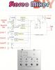
Mixing console diagram
Otherwise, this defect may look like this. The mixing console turns on, all the indicators are on, but there is no sound anywhere, the signal indicators are silent and do not react to anything.
This defect is associated with the power supply or its malfunction, when, instead of direct current, a variable is supplied to the board, which is enough to light up the LEDs, but the circuit is practically de-energized. Let me remind you that all consumer electronics are powered by a constant voltage obtained from a rectified variable voltage in an outlet. If the mixing console has a switching power supply, it doesn't seem to suffer from such defects, the unit simply does not start in the event of a breakdown and the mixing console looks dead.
Mixer won't turn on
This defect is often associated with an inoperative channel fader or volume control, or complete burnout of the stage on operational amplifiers (op-amp microcircuits). This repair is more protracted and expensive. requires a long search for burnt elements.
The most common reason for this is the burnout of the headphone channel microcircuits or the sticking of the output jack.
For the phantom power of the mixing console, as a rule, a separate converter is responsible, according to the multiplier circuit or a pulse Step-Up converter. Everything is trite: diodes, power switches, 4-5-8 leg assembly of the converter or a shorty in the load circuit between the converter and the XLR plug.
Repair of mixing consoles
This defect may appear due to poor contact in the signal circuits or failure of the pass-through separating capacitors, which leads to self-excitation of the path with subsequent amplification. It is treated with complete disassembly and search for burnt elements.
I will divide the repair of mixing consoles in Ryazan into several categories.
- Simple repair - diagnostics without disassembly. When a malfunction can be eliminated without disassembly and lengthy diagnostics. It rarely happens, but sometimes the fuse burns out or the cord is frayed. The price of the issue is 500 rubles.
- Regular repair (with disassembly) is a repair associated with a complete disassembly of the mixing console. The mixing console does not turn on, the channels do not work, the fader and everything described above will be stuck together. The disassembly assembly process takes a good part of the daylight hours and can take longer than the repair itself. Issue price 1500-3000r. + spare parts.
- Difficult renovation. In this case, it takes a lot of time to find a malfunction of the processor and its parts, dreary, long disassembly and diagnostics. Treat large consoles with 12 or more channels. The repair price is from 2500r to 10-20-30% of the cost of the mixer. To disassemble a 32-channel mixing console requires 2 square meters of storage space and diagnostics.
Repair of mixing consoles in Ryazan 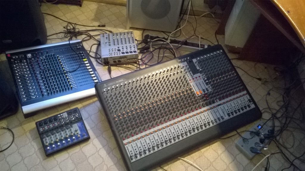 Repair of large mixing consoles
If you have the mixing console broke down in Ryazan and you urgently need to fix it, contact Sergofan - I will always be happy to help you.
I provide a guarantee for the work done. In addition to mixing consoles, I am engaged in the repair of active acoustic systems, in the common people of the column, as well as the repair of lighting equipment.
Repair of mixing consoles in Ryazan 8900-603-3879.
We repair mixing consoles of all brands and manufacturers. Any year of release. With any malfunctions. We also perform their tuning and diagnostics.
Repair of mixing consoles is our profession.
We give a guarantee for all repaired equipment.
Remember! Any attempt at self-repair can turn for you, at best, an increase in the cost of repairs, and at worst, the impossibility of repairing your equipment.
Mixer ("Mixer", or "mixing console", from the English "mixing console") - an electronic device intended for mixing sound signals: summing several sources into one or more outputs. Signal routing is also carried out using the mixing console. The mixing console is used for sound recording, mixing and concert sound reinforcement. There are analog and digital mixing consoles, and each of these types has its own supporters and opponents, as both types have their obvious advantages and disadvantages. Also mixing consoles differ in the number of inputs and outputs. Professional concert and studio mixing consoles usually have at least 32 inputs, more than 6 Aux buses, powerful equalizer on the inputs, 4 or more subgroups, and are also equipped with high-precision and long-throw faders. In turn, compact and budget mixers have a small number of channels, more meager equalizers, and are often devoid of faders (which are replaced by conventional potentiometers).
It is assumed that the customer knows the problem of the breakdown and does not require disassembly of the equipment to solve it. And also the customer has all the necessary spare parts in stock. (e.g. replacement of a connector, plug, etc.)
- The duration of the repair is no more than two days
- Diagnostics are not included in the price
In the first part of the article, it was told about the history of the emergence and development of remote controls (RCs) for controlling household television equipment.
Despite all the technological breakthroughs, the increase in the speed and the number of commands, the improvement in the design and noise immunity of the remote control are, perhaps, the most vulnerable node of television and video equipment. It is he who gradually or immediately stops working, perplexing the owners. Next, we will consider various typical malfunctions of remote controls and methods for their elimination.
The TV does not respond to any of the buttons on the remote control
Here the question immediately arises - what to do and who is to blame. It is undoubtedly necessary to start checking with what is simpler, namely with the remote control. First of all, you need to check if the remote control works at all. This is very easy to do.It is enough to bring the LED of the remote control to the camera lens, which is in any phone, and press any button. In this case, flashes of the remote control LED will be visible on the viewfinder screen. The color can be from white to bluish, everything seems to depend on the camera.
If these flashes are present, then we can assume that the remote control is almost operational. Pressing all buttons in turn allows you to test each button separately. Before doing this test, it is advisable to check the batteries. The easiest option is to replace the batteries with new ones or check the existing ones with a multimeter.
Checking batteries with a multimeter
The best way to do this is in the DC current measurement mode on the 10A range. At lower limits, it is possible to "blow" the 250mA fuse inside the device. Unlike rechargeable batteries, batteries are not afraid of short circuits, and if we manage to measure the current within 200..500mA, then everything is in order. It is better to check it separately for each battery, it is easier to hold it in your hands together with the test leads of the device.
If you measure the voltage on the batteries, then you need to load them, otherwise even unusable batteries can show the presence of voltage. In the process of checking - replacing the batteries, pay attention to the contact plates in the battery compartment. If oxide deposits or rust are found, the plates should be cleaned with sandpaper or even a small file.
To avoid scandals at home, the number of TVs must be at least two. This is the best option for checking a "suspicious" remote control. It’s probably known that remotes fit (or don’t fit) both home TVs.
If the batteries were changed, the camera was looked at, and there were no light pulses from this, then the remote control would have to be disassembled.
A small note: if the normal operation of the remote control stopped immediately after it was dropped on the floor, then first of all, after disassembly, you should pay attention to the ceramic resonator.
Disassembling the remote control
All consoles are arranged and disassembled in a rather monotonous manner. The first thing to do is remove the batteries from the battery compartment. In the same compartment, carefully look if there are any fastening screws here, as a rule, this is their place. But often there may be no screws at all. In this case, you can start dividing the remote control into two halves.
For this, a suitable tool, such as a screwdriver, is inserted into the joint. Some descriptions of this procedure say that the screwdriver can leave traces in the form of chips and scratches. Therefore, it is safer in this regard to use a regular credit card, which are issued in immeasurable quantities in any "magnet" or "pair". The main thing is to get successfully to the first latch without breaking it, and then gradually and carefully open the rest.
After the remote control is open, the lower part can be put aside for now. The entire remote control will remain in the upper part. The remote control with the bottom cover removed is shown in Figure 1.
Figure 1. Remote control with cover removed
Here we see the reverse side of the PCB. There is an IR LED on the left side, and the yellow square in the lower right corner is nothing more than a ceramic resonator. Here are the contacts of the battery compartment and the only electrolytic capacitor for the entire panel.
If, when checking with the camera, no signs of life were found, then you should immediately check the appearance of the LED and resonator, inspect their soldering. If they are oxidized or have ring cracks, then they must be re-soldered. It is better not just to pierce with a soldering iron, but to remove these parts from the board, clean and irradiate the leads, and only then put them back in place.
If you remove the PCB from the case, you will find a rubber base with buttons under it, as shown in Figure 2.
Figure 2. The buttons, when pressed, close the contact pads on the PCB.
The component side PCB is shown in Figure 3.
Figure 3. Remote controller board
Figure 3 shows the top of the rubber base with button pushers.
Figure 4. Upper part of the rubber base with pushers of the buttons of the remote control
When assembling the control panel, the mentioned pushers are inserted into the slots of the top cover (Figure 5), at the same time being the fixing element of the rubber base.
The pictures show everything quite decently and cleanly, since not long before that the console had undergone minor repairs. As a rule, any remote control opened for repair is a rather miserable and even heartbreaking sight.
What can be seen inside the remote control
The entire space where the rubber base with buttons is located is filled with a transparent sticky and viscous liquid that looks like an epoxy resin, only without hardener. This liquid is smeared with a neat thin layer, in places with small droplets. Even if you try, it won't work out so well and neatly right away.
This sticky liquid is everywhere. On the top and bottom of the rubber base of the buttons, on the top of the case with sockets for buttons. The top of the PCB with contact pads is also smeared with this glue ...
The origin of this glue is a matter of debate and even controversy in repair circles. Some say that it is grease from the fingers, others that it is fumes from batteries. But why, then, the lower part of the board, where there are no parts, is not covered with these fumes?
The most likely version seems to be that these sticky compounds come from the very rubber base itself. The rubber seems to be sweating, releasing plasticizers from itself, which indicates a violation of the technology for the production of rubber products. The only question that arises is why there are so many such substandard products? Indeed, in almost every remote control that gets into repair, just such a defect is noticed.
These evaporated plasticizers are most often the reason for the failure of the remote control. Outwardly, a similar defect manifests itself in the fact that the buttons stop "pressing", you have to increase the applied effort, but after a while this also does not lead to the passage of commands. You can press as hard as you like, for a long time, several times, but the channels do not switch, the volume is not regulated ...
Several repair methods
There are many recipes, advice and opinions on how to deal with this phenomenon. One source advises to immediately wipe all this disgrace with alcohol, gasoline or acetone, another says that in no case. Whom to believe? I will share my own limited experience in the field of remote control repair, there were not many clients, mainly relatives, neighbors and acquaintances, but the simplicity of the device and repair allows us to draw certain conclusions. And if you also listen to what is written on the Internet ...
Once cleaning such a remote control with alcohol led to its complete failure. If before cleaning only a few buttons (probably the most frequently used) worked poorly, then almost all of them stopped working. Therefore, I had to resort to another method of repair, but my memory was deposited that these buttons cannot be washed with alcohol.
A much better result, if the board has such a snotty look, can be obtained by washing the board and gum with buttons with not very hot water using a modern dishwashing detergent. It should be noted that here, too, you can overdo it: if you wash the rubber base with very vigorous movements and press harder, then the result can be exactly the opposite. The graphite coating from the buttons will be washed off, and you can then press them as much as you like, while not at all fearing that pressing the button will cause a channel change or volume control.
If the graphite coating has not been washed off before, then it should be washed with a soft cloth, with gentle, dabbing movements, which will never erase the graphite coating. The inside of the case and the PCB are best cleaned with a glass jar and bottle brush. It is quite good if, before washing off the snotty deposits, the parts of the disassembled remote control lie for some time, about 20 ... 30 minutes, in a detergent solution.
After washing, you should be patient, wait until the parts are dry, and only then assemble the remote control in the reverse order. If such a flushing gave a positive result, the remote control is working, you can only rejoice at the result. Otherwise, you can suggest several more repair methods.
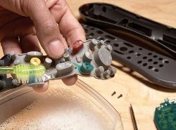
What to do if buttons are worn to the ground
For these situations, solutions already exist: repair kits for repairing the remote control are being sold. The bag contains a tube of glue and round graphite-coated rubber patches. Just spread and glue where you need to. There are even instructions on how to glue. A more modern version of the repair kit is self-adhesive patch. Everything is quite simple here. In such cases, it will not hurt to wipe the rubber buttons with alcohol or other solvent.
But, unfortunately, it is not possible to buy such semi-finished products everywhere and not always, although the price of the issue is simply ridiculous: where are we and where is the radio market. In these cases, you have to use various improvised means. One of the best available materials is paper-backed aluminum foil from cigarette packs. It is glued quite reliably and simply with any glue of the "Moment" type or superglue from small tubes.
Another option for repairing the remote control is to smear the buttons with conductive adhesives and varnishes, for example, "Kontaktol" or "Ellast". There are also many different opinions regarding this method, which is not yet clear better. Apparently, everything is simple: whoever succeeds well, he praises and vice versa.
| Video (click to play). |
Of course, modern prices for remote controls are not high, and it's easier than inventing something, go and buy a new one. But it happens that the TV is so old that not a single modern remote control is suitable. Most likely it's time to buy a new TV along with the remote control. Or, nevertheless, to repair the old remote control.


