In detail: do-it-yourself Philips monitor repair from a real master for the site my.housecope.com.
Today I want to share with you the experience of repairing a monitor with my own hands. I repaired my old one LG Flatron 1730s... Like this:
This is a 17 "LCD monitor. I must say right away that when there is no image on the monitor, we (at work) immediately refer such copies to our electronics engineer and he deals with them, but there was an opportunity to practice 🙂
To begin with, let's understand the terminology a little: earlier, CRT monitors (CRT - Cathode Ray Tube) were in use. As the name implies, they are based on a cathode ray tube, but this is a literal translation, it is technically correct to talk about a cathode ray tube (CRT).
Here is a disassembled sample of such a "dinosaur":
Nowadays LCD type of monitors (Liquid Crystal Display - display on the basis of liquid crystals) or simply LCD is in vogue. These designs are often referred to as TFT monitors.
Although, again, if we speak correctly, then it should be like this: LCD TFT (Thin Film Transistor - screens based on thin-film transistors). TFT is simply the most widespread variety, more precisely, LCD (liquid crystal) display technology.
So, before we start repairing the monitor ourselves, let's consider what “symptoms” did our “patient” have? In short: there is no image on the screen... But if you look a little more closely, then various interesting details began to emerge! 🙂 When turned on, the monitor showed an image for a split second, which immediately disappeared. At the same time (judging by the sounds), the system unit of the computer itself worked properly and the operating system was loaded successfully.
| Video (click to play). |
After waiting for a while (sometimes 10-15 minutes), I found that the image appeared spontaneously. Repeating the experiment several times, I was convinced of this. Sometimes for this, however, it was necessary to turn off and turn on the monitor with the "power" button on the front panel. After resuming the picture, everything worked without interruptions until the computer was turned off. The next day, history and the whole procedure were repeated again.
Moreover, I noticed an interesting feature: when the room was warm enough (the season is no longer summer) and the batteries were heated fairly, the idle time of the monitor without an image was reduced by five minutes. There was a feeling that it warms up, reaching the desired temperature regime and then works without problems.
This became especially noticeable after one day the parents (the monitor was with them) turned off the heating and the room became quite fresh. In such conditions, the image on the monitor was absent for about 20-25 minutes, and only then, when it got hot enough, did it appear.
According to my observations, the monitor behaved exactly like a computer with certain problems of the motherboard (capacitors that have lost capacity). If it is enough to warm up such a board (let it run or direct a heater towards it), it normally “starts up” and, quite often, works without interruptions until the computer is turned off. Naturally, this is - until a certain moment!
But at the early stage of diagnosis (before opening the patient's case), it is highly desirable for us to make the most complete picture of what is happening. According to it, we can roughly navigate in which node or element is the problem? In my case, after analyzing all of the above, I thought about the capacitors located in the power supply circuit of my monitor: we turn on - there is no image, the capacitors are warming up - it appears.
Well, it's time to test this assumption!
Let's disassemble! First, using a screwdriver, unscrew the screw that secures the bottom of the stand:
Then, - remove the corresponding screws and remove the base of the stand attachment:
Next, using a flat-tipped screwdriver, we pry the front panel of our monitor and in the direction indicated by the arrow, we begin to carefully separate it.
Slowly, we move along the perimeter of the entire matrix, gradually removing the plastic latches holding the front panel from their seats with a screwdriver.
After we disassembled the monitor (separated its front and rear parts), we see the following picture:
If the “insides” of the monitor are attached to the back panel with adhesive tape, peel it off and remove the matrix itself with the power supply and control board.
The back plastic panel remains on the table.
Everything else in the disassembled monitor looks like this:
This is how the “filling” looks in the palm of my hand:
Let's show a close-up of the panel of settings buttons that are displayed for the user.
Now, we need to disconnect the contacts connecting the cathode backlight lamps located in the monitor matrix with the inverter circuit responsible for their ignition. To do this, we remove the aluminum protective cover and see the connectors under it:
We do the same on the opposite side of the monitor's protective casing:
Disconnect the connectors from the monitor inverter to the lamps. Who cares, the cathode lamps themselves look like this:
They are covered on one side with a metal casing and are located in it in pairs. The inverter “lights up” the lamps and adjusts the intensity of their light (controls the brightness of the screen). Now, instead of lamps, LED backlights are increasingly used.
Advice: if you find that on the monitor suddenly the image is gone, take a closer look (if necessary, illuminate the screen with a flashlight). Perhaps you will notice a faint (faint) image? There are two options here: either one of the backlight lamps is out of order (in this case, the inverter simply goes “in defense” and does not supply power to them), remaining fully operational. The second option: we are dealing with a breakdown of the inverter circuit itself, which can either be repaired or replaced (in laptops, as a rule, they resort to the second option).
By the way, the laptop inverter is located, as a rule, under the front outer frame of the screen matrix (in the middle and bottom of it).
But we got distracted, we continue to repair the monitor (more precisely, for now, chick it) 🙂 So, having removed all the connecting cables and elements, we disassemble the monitor further. We open it like a shell.
Inside we see another cable connecting, protected by another casing, the matrix and monitor backlight lamps with the control board. Peel off the scotch tape up to half and see under it a flat connector with a data cable in it. We carefully remove it.
We put the matrix separately (we will not be interested in it in this repair).
This is how it looks from the back:
Taking this opportunity, I want to show you the disassembled monitor matrix (recently they tried to repair it at work). But after analysis, it became clear that it would not be possible to fix it: some of the liquid crystals on the matrix itself burned out.
In any case, I shouldn't have seen my fingers behind the surface so clearly! 🙂
The die is secured in a frame that holds and holds all of its parts together using snug plastic snaps. In order to open them, you will have to work thoroughly with a flat screwdriver.
But with the type of do-it-yourself monitor repair that we are doing now, we will be interested in another part of the design: the control board with the processor, and even more so, the power supply of our monitor. Both of them are shown in the photo below: (photo - clickable)
So, in the photo above, on the left, we have the processor board, and on the right, the power board combined with the inverter circuit. A processor board is often referred to as a scaler board (or circuit).
The scaler circuit processes the signals coming from the PC. In fact, a scaler is a multifunctional microcircuit, which includes:
- microprocessor
- a receiver (receiver) that receives a signal and converts it into the desired form of data, transmitted via digital interfaces for connecting a PC
- an analog-to-digital converter (ADC) that converts the input analog R / G / B signals and controls the resolution of the monitor
In fact, a scaler is a microprocessor optimized for the task of image processing.
If the monitor has a frame buffer (random access memory), then work with it is also carried out through the scaler. For this, many scalers have an interface for working with dynamic memory.
But we - again distracted from the repair! Let's continue! 🙂 Let's take a close look at the monitor power combo board. We will see such an interesting picture there:
As we assumed at the very beginning, remember? We see three swollen capacitors requiring replacement. How to do it correctly is described here in this article of our site, we will not be distracted once again.
As you can see, one of the elements (capacitors) swelled not only from above, but also from below, and some of the electrolyte flowed out of it:
To replace and effectively repair the monitor, we will need to completely remove the power board from the casing. We unscrew the fastening screws, take out the power cable from the connector and take the board in our hands.
Here is a photo of her back:
I want to say right away that quite often the power board is combined with the inverter circuit on one PCB (printed circuit board). In this case, we can talk about a combination board, represented by the power supply of the monitor (Power Supply) and the inverter of the backlight (Back Light Inverter).
In my case, this is exactly the case! We see that in the photo above, the lower part of the board (separated by a red line) is, in fact, the inverter circuit of our monitor. It happens that the inverter is represented by a separate PCB, then there are three separate boards in the monitor.
The power supply (the upper part of our PCB) is based on the FAN7601 PWM controller microcircuit and the SSS7N60B field-effect transistor, and the inverter (its lower part) is based on the OZL68GN microcircuit and two FDS8958A transistor assemblies.
Now we can safely start repairing (replacing capacitors). We can do this by conveniently placing the structure on the table.
This is how the area of interest to us will look after removing faulty elements from it.
Let's take a close look at what nominal capacitance and voltage do we need to replace the elements soldered from the board?
We see that this is an element with a rating of 680 microfarads (mF) and a maximum voltage of 25 volts (V). In more detail about these concepts, as well as about such an important thing as maintaining the correct polarity when soldering, we talked with you in this article. So, let's not dwell on this again.
Let's just say that we have failed two 680 mF capacitors with a voltage of 25V and one at 400 mF / 25V. Since our elements are connected in parallel to the electrical circuit, we can safely use two 1000 mF capacitors instead of three capacitors with a total capacity (680 + 680 + 440 = 1800 microfarads), which will add up to the same (even greater) capacitance.
The capacitors removed from our monitor board look like this:
We continue to repair the monitor with our own hands, and now it is time to solder the new capacitors in place of the removed ones.
Since the elements are really new, they have long “legs”. After soldering in place, just carefully cut off their excess with side cutters.
As a result, we got it like this (for the sake of order, for two 1000 microfarad capacitors, I put an additional 330 mF element on the board).
Now, we carefully and carefully reassemble the monitor: fasten all the screws, connect all cables and connectors in the same way, and, as a result, we can proceed with an intermediate test run of our half-assembled structure!
Advice: there is no point in putting the entire monitor back together, because if something goes wrong, we will have to disassemble everything from the very beginning.
As you can see, the frame, signaling the absence of a connected data cable, appeared immediately.This, in this case, is a sure sign that the repair of the monitor with our own hands was successful with us! 🙂 Previously, until the malfunction was corrected, there was no image at all until it warmed up.
Mentally shaking hands with ourselves, we assemble the monitor to its original state and (for testing) we connect it with a second display to the laptop. We turn on the laptop and see that the image immediately "went" to both sources.
Q.E.D! We just repaired our monitor ourselves!
note: To find out what other types of TFT monitor malfunctions there are, follow this link.
That's all for today. I hope this article was helpful to you? See you next on the pages of our site 🙂
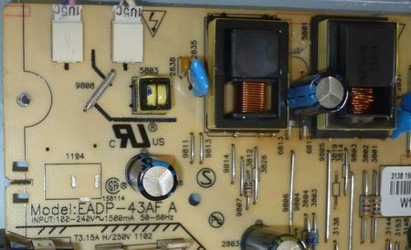
Rice. Monitor Philips 170B6, inverter EADP-43AF
Declared malfunction.
The monitor turns on - but turns off after two or three seconds.
Additional signs.
When viewing the monitor screen at an angle, you can see that there is a picture, but the CCFL lamps do not work.
Renovation work.
The faulty element is quite simple - HF transformer 5801 (IT-E19-NB4004B). The transformer could not be found, I had to rewind.
For reference
The inverter uses two types of transformers - IT-E19-NB4004B and IT-E19-NB4005B, the only difference is that the transformers are mirror images of each other.
For reference
The inverter uses two types of transformers - IT-E19-NB4004B and IT-E19-NB4005B, the only difference is that the transformers are mirror images of each other.
After rewinding the HF transformer, the monitor started up and the defect was eliminated. But rather another, no less interesting defect came to light, the monitor worked when disassembled - not when assembled. This happens - if there is a defect in the high-voltage wires and they are shortened to the body, but this was not the case, the wires were in perfect condition. Through simple experiments, it turned out that all the problems were associated with the upper CCFL lamp, which was ignited by the previously rewound 5801 transformer (IT-E19-NB4004B). The defect manifested itself in the following way - the monitor worked if the test and obviously working CCFL lamp lay separately from the case, as soon as it was put on the case, the inverter immediately went into protection.
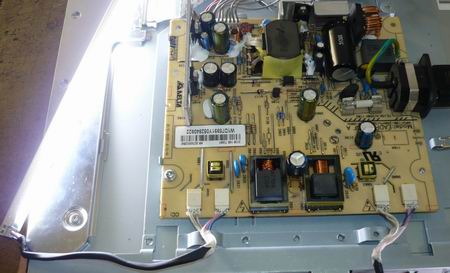
Rice. Monitor Philips 170B6, inverter EADP-43AF it is worth putting the upper lamp on the body, as the protection is triggered, the position of the lower lamp does not matter
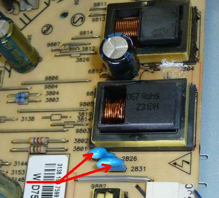
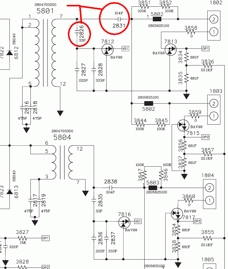
Everything is somewhat ambiguous here, so we change the capacitor 2826 (33pF * 2kV) and 2831 (0.1uF).
Rice. Monitor Philips 170B6, inverter EADP-43AF marked with faulty items
Rice. Monitor Philips 170B6, inverter EADP-43AF marked with faulty items
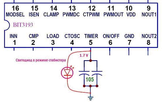
Rice. BIT3193 classic of the genre, disable protection.
Even if it's a pity for the LED, you can simply throw one lamp from the top pair to the bottom pair, and from the bottom to the top one, then the defect will disappear, it has been checked more than once. Total repairs would have been done in 30-40 minutes without the need for those. running and without replacing lamps and transformer.
We increasingly often hear complaints about sudden breakdowns of LCD monitors, and most of them happen just like that, for no apparent reason. Most often they just "die" parts for monitors, moreover, simply because their resource has been exhausted. It turns out that the idea that every device has a time-bomb is not such a utopia.
Take liquid crystal displays, for example. Here's why they should fail - they have no moving parts, or components that can burn out - only semiconductors. In monitors, the weak link may be CCFL lamps - luminescent, with a cold cathode, intended for matrix illumination. They really do not differ in durability, and, at first, their brightness decreases, and then they completely fail. You can replace them with more reliable LED lamps.
Power sources can also give "slack". Even the most modern and super-sophisticated devices have a converter that divides 220 V into small voltages that are required for each circuit. Burnt out backlight inverter can extinguish the entire display, regardless of where and when it was produced.And then, there comes that not very beautiful day when the monitor does not turn on. In this case, it does not matter whether the power-on indicator is on or not, but the image on the screen does not appear.
The easiest way to fix a monitor, which power source is a separate box or plug adapter, than the one with which it is hidden inside the case. Indeed, in the first case, you can simply change the burned-out parts for monitors, finding similar power sources from old equipment in the bins, or buy spare parts for the monitor at the nearest radio market.
There is no need to disassemble the display case, so even a beginner can handle this task. The main thing is to choose an adapter with a voltage the same as that of the old device, otherwise you will ruin the entire system, and then even the service center will not be able to help you.
To understand where the monitor's power supply is located, you need a tester (multimeter). Use it to measure the voltage on the plug, and from the results you will understand where the “legs grow” from. If the voltage is low or unstable, connect the bulbs in series, about 5-10 W, and check the voltage again. If the adapter is broken, then it will not be able to hold the voltage, or emit a heart-rending whistle. It is better to replace such a power source with a new one right away.
Repairing a Philips TV with your own hands - a similar idea comes to a large number of people who have encountered problems with the operation of such equipment. The very idea of the opportunity to save money on calling the master arouses great enthusiasm, while the opportunity to repair the equipment on your own will allow you to continue to contemplate your favorite films, resting in the evening, and not have to wait until the master finishes the repair and finally provides the result. However, is it justified to repair a Philips TV with your own hands if it does not turn on? This issue is controversial enough. Now we will find the answer to it.
On the one hand, certain measures are quite appropriate:
- If there is no picture, and the TV does not turn on at all, it makes sense to make sure that it is connected to the mains and the electricity is not turned off. Paradoxically, this advice helps a lot of people.
- If there is no sound, it is also worth checking the settings, because it may well be that the children were playing with the remote control, or you yourself accidentally turned it off.
Do-it-yourself Philips TV repair is advisable precisely within the framework of such measures, but if this approach could not help, and we are really talking about a major and serious breakdown, you should not try to disassemble the thing with your own hands, even if you assume that you can do it. Moreover, if you do not have any skills in working with radio and TV equipment.
Important! Considering the schemes for the repair of Philips TVs, in no case forget that tampering with the structure can be quite dangerous, because the residual voltage remains even when the equipment is disconnected from the mains.
In addition, you should remember that modern TVs are high-tech and rather thin devices, so even specialists do not want to repair them at home. It will be quite easy to break the TV and bring it to a state in which it will no longer be possible to return it to work.
The cost of repairing in workshops is not so high that you risk an expensive device trying to repair it yourself without the proper professionalism.
Important! If you are at the stage of choosing a new brand and model of TV, then the information described in the articles will be useful for you:
In the event that during switching on the TV often blinked green LEDs, this indicates that the malfunction lies directly in the power supply. So, how to repair your Philips TV yourself:
- Place the TV on a flat and level surface. Remove the four mounting screws from the back of your TV. The slot of the screws is an asterisk.
- Remove the two screws that secure the TV legs.
- Lift the back cover. In the upper right corner, you will see the power supply board.
- Take a close look at the appearance of all capacitors. The knurled top covers must be flat. If there is a swelling or opening, then the part must be replaced.
- Purchase, pick up faulty electrolytic capacitors.
Important! Try to install analogs that exactly correspond to the capacitance; a higher operating voltage can be used. And do not buy the cheapest capacitors or parts with suspicious markings.
- Remove the two screws from the power supply board securing. Disconnect the top and right connectors. The details have been fully accessed. Unsolder capacitors and install new ones.
- Assemble your TV. Don't forget to connect the connectors.
- Connect the TV to the network.
Important! The goods market offers a huge selection of models from different manufacturers with all sorts of characteristics. We have prepared a rating of TVs of two companies Samsung and LG - you can watch it by clicking on the link "Rating of 4K TVs".

