In detail: DIY repair of the viewsonic va2216w monitor from a real master for the site my.housecope.com.
Good day to the forum participants!
Monitor Viewsonic va2216w
model code VA2216W-4 VS11803
bp e131175
control board 490741300200r
tsumu58wj-lf processor
matrix chunghwa claa220wa
Malfunction - White Screen
Eliminated faults
replaced the q101 transistor on the control board with apm3095p since the + 5v power supply did not reach the matrix
replaced the loop to the matrix
replaced the fuse at the power input + 5v matrix
replaced broken ceramic capacitors parallel to the matrix fuse
at matrix input + 5v only 4.9v available
only 4.8v comes to the source of the crank
test point voltages
gnd
vddg 24.2v
vdda 13v
veeg -6.5v
vddd 3.3v
veeg -6.5v
gnd
when the power is turned off, the voltages are removed
at the moment, when the monitor is turned on, the u200 choke whistles, the image in the form of an inscription is not observed, after 1 second it smoothly flows into the white screen.
After 3 years of operation, the monitor began to podglyuchitsya, the sound became somehow hoarse, and on the screen when the brightness decreased from the maximum, horizontal stripes appeared.
Unscrew the leg mount
Unscrew the 2 bolts securing the cover
Next, carefully pry the cover around the perimeter with a screwdriver
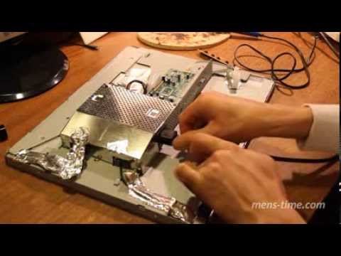
Next, unscrew the metal cover that covers the main control unit
We take out all the connectors around the perimeter
Unscrew the D-SUB connector bolts
Removing the metal cover
And a board with a power supply, a backlight unit and a sound amplifier
And here are 2 reasons for glitches, 2 capacitors are swollen
We disassemble further, disconnect 2 loops going to the LCD panel
Actually, we need it
| Video (click to play). |
To disassemble everything, unscrew the LCD panel board
We solder 2 swollen ones, solder 2 new ones
The photo shows a swelling and a crack
Already with working capacitors
The result itself, the sound also became normal
Judging by the clock on the monitor, I did it in an hour
I can't find the DAC-12M030 schematic. The problem is that the monitor screen after switching on (the LED turns green) starts to glow with a steady white light, then after five seconds it goes out (the LED is yellow). I would be glad to get at least a photo of the reverse side of this board in the area of L7812CV (this is the lower left corner in the 22nd photo) with a high resolution, since you need to restore the burned-out tracks on the board.
I am also interested in the DAC-12M030 circuit, the monitor turns on the backlight and after 1 sec extinguishes, capacitors, transformers, lamps changed ... I wonder how lamps connected through small transformers work (Fig. 14, upper right corner of the board), maybe they have a problem.
Good topic, by the way, where can I get this template?
my monitor won't turn on at all. what should i do?
First, check the fuse, if the whole voltage is at the output of the power supply.
The same trouble. does not turn on at all. True, 1913. 🙂 Where is his fuse?
Thanks a lot! My monique lasted longer - 6 years, the same symptoms. Yesterday they disassembled according to the instructions laid out - the same conders died))) I'm going to the store for new ones ...
Good luck with the repair, do not mix up the polarity 🙂
the problem with the DAC-12M030 replaced almost all the conductors, the PWM still does not want to start after 220 is supplied, the green LED turns on after 5 seconds, it goes out and so on all the time. I listened to the sounds before the LED goes out and the silk goes out and o5 all over again. can still change optocouplers?
Perhaps the protection is triggered, check for a short circuit of 12 and 5 V
Have you changed the input capacitor? which is 300 volts
have not changed yet, but the desire is already there.
Today I took up Monique, turned it on more thoroughly in idle mode, began to measure all voltages, found out a strong blockage in all voltages, the microcircuit located in U201 P605BD6H18 is very hot, the rest are not. this is when the lamps are off. clicks of protection operation are heard. picture of the work done
If the microcircuit is heating up, then it is possible that the turns on the step-up transformer are closed, the option of checking is to swap the transformers and check if another microcircuit is warming up (but if it burned out as a result of a breakdown of the winding, then there is a possibility that three will also burn out) you can also measure the resistance on the windings transformer (evaporate!) and compare.
I just rang her, without raising my legs, it rings shortly, unlike the others. for the rest, depending on which leg, the resistance is about 500 ohms
it is desirable to solder everything, perhaps this microcircuit burned out, but it could have burned out either simply, or because of a faulty transformer, nevertheless measure and compare the resistance on the secondary winding of the transformers, if on the faulty one the turns are closed less, it happens, because there is a high voltage.
Hello to all ! I have a viewsonic va1912w monitor, a dac-12mo30 board - the monitor turns on and after a couple of seconds it turns off at this time, the display just has a white screen (((visually everything is intact on the board when I connect it to the computer, it is SO and the display is white (((the chip is heated on another like all the conduits in Norma are not swollen, please help me. I’m a BEGINNER!
If the chip heats up, then most likely there is a problem in it, but it turns off because the protection in the power supply is triggered, you need to find out how much this chip consumes. Write one hundred for the chip, let's see what to do next with it.
The chip heats up only when I turn on the monitor, that is, when the screen is white!
aaaa I understood everything right now I will stay!
Now you can 🙂
at the bottom “Add Image”
this chmp heats up when I turn on Monique
but how to check whether the kander is working or not.
Conders usually swell, and in order to check you need to solder, and check the capacity, you can use an ordinary tester, but you need to know how.
First, check the voltages, there should be +5 and 12 volts, check when the chip heats up to see if these voltages sag. Perhaps the chip is covered and consumes a lot. If the voltages are sluggish, then you can unsolder the power supply suitable for the chip and again check the voltages, if the voltages are set back to normal, then the chip is probably out of order. also check with the display turned off, these are those 2 white loops.
how to check. I'm a full kettle!
from the power supply goes through the 5 volt connector in standby mode and 12 is added in the on state, so they need to be checked with the device.
see here https://my.housecope.com/wp-content/uploads/ext/2817/delta-dac-19m008.html in the table CN5 plug 8 pin 13.8V 9.10 pin 5v
thank you all right now I will stay
in short, I don’t know changed all the kander did NOT help ((((((((((((((((((((
see here https://my.housecope.com/wp-content/uploads/ext/2817/delta-dac-19m008.html in the table CN5 plug 8 pin 13.8V 9.10 pin 5v
see here https://my.housecope.com/wp-content/uploads/ext/2817/delta-dac-19m008.html in the table CN5 plug 8 pin 13.8V 9.10 pin 5v
5v shows, but 11.84 8pin - what's the matter?
I think 11.84 is ok. By the way, when it is connected to a computer, it turns off or just lights up white and that's it?
when you connect it to a computer, it lights up white, then after a few seconds a different color of the strip on the screen
and when without a cord, then for 5 seconds the white screen turned on and everything turned off to yellow
In standby mode after 5 seconds, this is normal, but if the stripes are thin, then this is a Khan matrix or CPU, can I have a photo of these stripes?
and can you make a matrix?
the chip is still heating in any mode!
This is a sound amplifier, you can pull it out for now.
Most likely, either the matrix or the chip responsible for the formation of the picture flew, In general, it is easier to buy a new monitor 🙂
well, just want to do it! do you think they will take it for spare parts?
right now I'm soldering the sound board, I'll try it, we can do it
If it is heated so that the finger can be held, then it is normal, if it is hot, it already stinks, then it is not normal. some mikruhi can heat up to 80 degrees. They will take them for spare parts, but only for free 🙂 because they are a hell of a lot right now, and they cost a penny.
thanks for the help anyway.
don't just add
in friends list
umenya manitor ne rabotayet
mojet chem nibud pomojite ??
You are not a bad repairman. And there were no more complex defects. There are many more things that burn out. Lucky. Here is also a description of the repair of this monik. https://my.housecope.com/wp-content/uploads/ext/2254/section33/topic178817.html Well done. )))
Many thanks to the author for the detailed photo report and article.
And then he already wanted to carry his Monique into the trash
Good day!
BLACK MONITOR.
I ask you to respond, who participated in this topic - help, direct.
ViewSonic VA1912w NVIDIA, GeForce 8600 GT
Prehistory:
- it began about 5 years ago (I think so, I tie it all together) - a long story, who
asks, I'll tell you in detail 🙂
Recent symptoms:
- in normal mode, the system boots up for about 4 minutes.
- my actions to date:
- button on
- indicator orange 8 min. (Waiting)
- I disconnect (pull) the connection (monitor plug - network) from the monitor, insert
back, the desktop appears through the splash.
The system itself boots normally - you can hear it by the sounds ...
This has been going on for more than six months, but with different solutions. Described the last
inclusion. I come to each inclusion by "typing".
Toli card. roofing felts monitor. roofing felts cable. roofing felts what else.
Thanks, I hope for an answer.
Good day!
BLACK MONITOR.
I ask you to respond, who participated in this topic - help, direct.
ViewSonic VA1912w NVIDIA, GeForce 8600 GT
Prehistory:
- it began about 5 years ago (I think so, I tie it all together) - the story is long, who will ask, I will tell you in detail 🙂
Recent symptoms:
- in normal mode, the system boots up for about 4 minutes.
- my actions to date:
- button on
- indicator orange 8 min. - waiting - turning green
- I disconnect (pull) the connection (plug monitor - network) from the monitor, insert it back, the desktop appears through the splash - you can start working ...
The system itself boots normally - you can hear it by the sounds ...
This has been going on for more than six months, but with different solutions. Described the latest inclusion solution. I come to each inclusion by "typing".
And so every turn on, reboot is normal.
Toli card. roofing felts monitor. roofing felts cable. roofing felts what else.
Thanks waiting for an answer.
my va1912w blinks at startup for several minutes, each time more and more. Think lamps. Where to get them or how to switch to diodes?
To begin with, check the capacitors, 90% because of them, At work, one of the monitors also blinks for about 3 minutes, I think my hands will soon reach it, and a new article will appear.
processor TSUMU58WJ-LF memory 24C04WI
Hello. The monitor turns on, it works for a cold one for about a minute, and the backlight goes out, the LED of the power button goes out, after five seconds it turns on itself and then works in the same style, that is, it turns on and off with an interval of 5 seconds. If you discard the signal from the port vzha, then it goes into the duty room and does not turn off. That is, turning on and off occurs only when a signal is applied to the input.
Voltage 5 V. coming from the power supply, when it is turned off, drops to 1.6 volts. During the period when the monitor is working, the voltage on the control board is 3.3V and 1.8V. The only thing that is embarrassing is that 5 V comes to the control board, and when fed through a diode to a 3.3 V stabilizer, it sits down to 4.7 V. This is fine? Well, where, actually, to dig.
all capacitors were replaced on the power supply unit and the control board
Not a bad monitor for the budget, it worked for 7 years and began to mope. When turned on, the screen lights up and after 2 seconds it goes out, you press the on-off button, the screen turns on again and after a second it goes out again.
Write review Viewsonic VA2216w
Describe how satisfied or dissatisfied you are with your purchase Viewsonic VA2216w
DOES NOT INCLUDE. NORMAL CONDES NO PROGRAMS. NO BLOOD. ALMOST EVERYTHING IS GOOD. IF ON WHO CAN HELP.
the monitor worked for almost three years. but now there is a problem, after turning it on, it works for about three minutes. and then the screen goes blank. I press off, then on turns on but no longer for more than a minute. what could be the problem? the impression is that somewhere the contact heats up and disappears.
A ViewSonic VA1916W-2 LCD monitor came in for repair with a declared malfunction - it fell, now it does not turn on. The consequences of a fall are very clearly visible on the upper left corner of the monitor.
We turn on, check the malfunction. The monitor turns on for a few seconds and then the backlight goes out. The malfunction was confirmed. We will disassemble.
Remove the plastic latch that covers the screws that secure the stand to the monitor.
Unscrew 4 screws under it:
Remove the monitor footrest and set it aside:
We take a pick and carefully snap off the back cover of the monitor along its entire length:
We check the backlight lamps by throwing in 100% working lamps:
We turn on the monitor and make sure that if you put a 100% working lamp instead of the upper red lamp, then the backlight works in normal mode:
That is, the top red lamp is to blame for our malfunction. Well, let's change the lamp. Carefully disconnect the cable leading to the control buttons:
And remove the bezel to the side:
Disconnect the cables from the matrix and the lamp from the inverter board:
Unscrew the two screws that secure the monitor power connector:
and unscrew the screws securing the VGA connector:
We remove the piece of iron that covers the inverter board, unscrew the three screws securing the matrix board and fold the matrix board gently up.
We leave the matrix itself on the table, and take the rest to the side:
We take out the upper assembly of lamps. We see that one of the lamps is cracked. This is just a red lamp. The blow did its dirty work.
We change it. (I replaced only one lamp, but it is easier, of course, to replace the entire assembly at once). The assembly in this monitor is 42.6 cm long. And the lamp is 42.1 cm.
We put the lamp assembly back in place:
Putting everything together in reverse order, at the same time glue the upper left corner of the monitor. We include.
We put on a four-hour run with periodic on-off. Everything is working.
All photos were taken with a Kodak EasyShare C1530 camera.
Created: 02 August 2016 Tue 17:50:30.
Section: "Radio and Electronics"
Messages in topic: 20, views: 4969
Site Admin
The problem is this: the ViewSonic VA2216w-2 monitor was in working order, stood idle for six months in the closet and now does not want to turn on normally - the blue indicator blinks and that's it. A similar problem is googled - they say that capacitors are dying.
Dismantled, looked at the capacitors - seemingly normal, not swollen. It is not clear how to determine which of them are problematic.
Well, since the monitor died from prolonged non-use, can it come to life with constant voltage? He stood all night connected to the network - and it is true, in the morning after several attempts he did turn on. But the problem as such has not disappeared, although sometimes it is possible to turn it on, but only after several attempts, there is no stability, obviously some element in this system has aged.
A question for connoisseurs: what would you advise in this situation? Maybe this is a specific problem for this type of monitors and has some known solution? Changing all the capacitors in a row is stupid, they are different there, for sure the problem is not with all, but with some one.
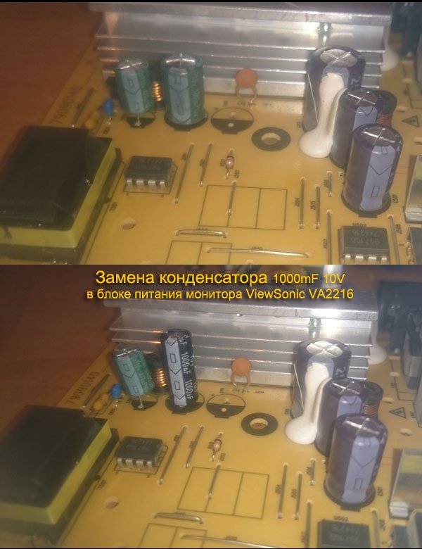
UPD. The issue is resolved by replacing the 1000mF 10V capacitor, see photo
Today I want to share with you the experience of repairing a monitor with my own hands. I repaired my old one LG Flatron 1730s... Like this:
This is a 17 "LCD monitor. I must say right away that when there is no image on the monitor, we (at work) immediately refer such copies to our electronics engineer and he deals with them, but there was an opportunity to practice 🙂
To begin with, let's understand the terminology a little: earlier, CRT monitors (CRT - Cathode Ray Tube) were in use. As the name implies, they are based on a cathode ray tube, but this is a literal translation, it is technically correct to talk about a cathode ray tube (CRT).
Here is a disassembled sample of such a "dinosaur":
Nowadays LCD type of monitors (Liquid Crystal Display - display on the basis of liquid crystals) or simply LCD is in vogue. These designs are often referred to as TFT monitors.
Although, again, if we speak correctly, then it should be like this: LCD TFT (Thin Film Transistor - screens based on thin-film transistors). TFT is simply the most widespread variety, more precisely, LCD (liquid crystal) display technology.
So, before we start repairing the monitor ourselves, let's consider what “symptoms” did our “patient” have? In short: there is no image on the screen... But if you look a little more closely, then various interesting details began to emerge! 🙂 When turned on, the monitor showed an image for a split second, which immediately disappeared. At the same time (judging by the sounds), the system unit of the computer itself worked properly and the operating system was loaded successfully.
After waiting for a while (sometimes 10-15 minutes), I found that the image appeared spontaneously. Repeating the experiment several times, I was convinced of this. Sometimes for this, however, it was necessary to turn off and turn on the monitor with the "power" button on the front panel. After resuming the picture, everything worked without interruptions until the computer was turned off. The next day, history and the whole procedure were repeated again.
Moreover, I noticed an interesting feature: when the room was warm enough (the season is no longer summer) and the batteries were heated fairly, the idle time of the monitor without an image was reduced by five minutes. There was a feeling that it warms up, reaching the desired temperature regime and then works without problems.
This became especially noticeable after one day the parents (the monitor was with them) turned off the heating and the room became quite fresh. In such conditions, the image on the monitor was absent for about 20-25 minutes, and only then, when it got hot enough, did it appear.
According to my observations, the monitor behaved exactly like a computer with certain problems of the motherboard (capacitors that have lost capacity). If it is enough to warm up such a board (let it run or direct a heater towards it), it normally “starts up” and, quite often, works without interruptions until the computer is turned off. Naturally, this is - until a certain moment!
But at the early stage of diagnosis (before opening the patient's case), it is highly desirable for us to make the most complete picture of what is happening. According to it, we can roughly navigate in which node or element is the problem? In my case, after analyzing all of the above, I thought about the capacitors located in the power supply circuit of my monitor: we turn on - there is no image, the capacitors are warming up - it appears.
Well, it's time to test this assumption!
Let's disassemble! First, using a screwdriver, unscrew the screw that secures the bottom of the stand:
Then, - remove the corresponding screws and remove the base of the stand attachment:
Next, using a flat-tipped screwdriver, we pry the front panel of our monitor and in the direction indicated by the arrow, we begin to carefully separate it.
Slowly, we move along the perimeter of the entire matrix, gradually removing the plastic latches holding the front panel from their seats with a screwdriver.
After we disassembled the monitor (separated its front and rear parts), we see the following picture:
If the “insides” of the monitor are attached to the back panel with adhesive tape, peel it off and remove the matrix itself with the power supply and control board.
The back plastic panel remains on the table.
Everything else in the disassembled monitor looks like this:
This is how the “filling” looks in the palm of my hand:
Let's show a close-up of the panel of settings buttons that are displayed for the user.
Now, we need to disconnect the contacts connecting the cathode backlight lamps located in the monitor matrix with the inverter circuit responsible for their ignition. To do this, we remove the aluminum protective cover and see the connectors under it:
We do the same on the opposite side of the monitor's protective casing:
Disconnect the connectors from the monitor inverter to the lamps. Who cares, the cathode lamps themselves look like this:
They are covered on one side with a metal casing and are located in it in pairs. The inverter “lights up” the lamps and adjusts the intensity of their light (controls the brightness of the screen). Now, instead of lamps, LED backlights are increasingly used.
Advice: if you find that on the monitor suddenly the image is gone, take a closer look (if necessary, illuminate the screen with a flashlight). Perhaps you will notice a faint (faint) image? There are two options here: either one of the backlight lamps is out of order (in this case, the inverter simply goes “in defense” and does not supply power to them), remaining fully operational. The second option: we are dealing with a breakdown of the inverter circuit itself, which can either be repaired or replaced (in laptops, as a rule, they resort to the second option).
By the way, the laptop inverter is located, as a rule, under the front outer frame of the screen matrix (in the middle and bottom of it).
But we got distracted, we continue to repair the monitor (more precisely, for now, chick it) 🙂 So, having removed all the connecting cables and elements, we disassemble the monitor further. We open it like a shell.
Inside we see another cable connecting, protected by another casing, the matrix and monitor backlight lamps with the control board. Peel off the scotch tape up to half and see under it a flat connector with a data cable in it. We carefully remove it.
We put the matrix separately (we will not be interested in it in this repair).
This is how it looks from the back:
Taking this opportunity, I want to show you the disassembled monitor matrix (recently they tried to repair it at work). But after analysis, it became clear that it would not be possible to fix it: some of the liquid crystals on the matrix itself burned out.
In any case, I shouldn't have seen my fingers behind the surface so clearly! 🙂
The die is secured in a frame that holds and holds all of its parts together using snug plastic snaps. In order to open them, you will have to work thoroughly with a flat screwdriver.
But with the type of do-it-yourself monitor repair that we are doing now, we will be interested in another part of the design: the control board with the processor, and even more so, the power supply of our monitor. Both of them are shown in the photo below: (photo - clickable)
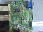
So, in the photo above, on the left, we have the processor board, and on the right, the power board combined with the inverter circuit. A processor board is often referred to as a scaler board (or circuit).
The scaler circuit processes the signals coming from the PC. In fact, a scaler is a multifunctional microcircuit, which includes:
- microprocessor
- a receiver (receiver) that receives a signal and converts it into the desired form of data, transmitted via digital interfaces for connecting a PC
- an analog-to-digital converter (ADC) that converts the input analog R / G / B signals and controls the resolution of the monitor
In fact, a scaler is a microprocessor optimized for the task of image processing.
If the monitor has a frame buffer (random access memory), then work with it is also carried out through the scaler. For this, many scalers have an interface for working with dynamic memory.
But we - again distracted from the repair! Let's continue! 🙂 Let's take a close look at the monitor power combo board. We will see such an interesting picture there:
As we assumed at the very beginning, remember? We see three swollen capacitors requiring replacement. How to do it correctly is described here in this article of our site, we will not be distracted once again.
As you can see, one of the elements (capacitors) swelled not only from above, but also from below, and some of the electrolyte flowed out of it:
To replace and effectively repair the monitor, we will need to completely remove the power board from the casing. We unscrew the fastening screws, take out the power cable from the connector and take the board in our hands.
Here is a photo of her back:
I want to say right away that quite often the power board is combined with the inverter circuit on one PCB (printed circuit board). In this case, we can talk about a combination board, represented by the power supply of the monitor (Power Supply) and the inverter of the backlight (Back Light Inverter).
In my case, this is exactly the case! We see that in the photo above, the lower part of the board (separated by a red line) is, in fact, the inverter circuit of our monitor. It happens that the inverter is represented by a separate PCB, then there are three separate boards in the monitor.
The power supply (the upper part of our PCB) is based on the FAN7601 PWM controller microcircuit and the SSS7N60B field-effect transistor, and the inverter (its lower part) is based on the OZL68GN microcircuit and two FDS8958A transistor assemblies.
Now we can safely start repairing (replacing capacitors). We can do this by conveniently placing the structure on the table.
This is how the area of interest to us will look after removing faulty elements from it.
Let's take a close look at what nominal capacitance and voltage do we need to replace the elements soldered from the board?
We see that this is an element with a rating of 680 microfarads (mF) and a maximum voltage of 25 volts (V). In more detail about these concepts, as well as about such an important thing as maintaining the correct polarity when soldering, we talked with you in this article. So, let's not dwell on this again.
Let's just say that we have failed two 680 mF capacitors with a voltage of 25V and one at 400 mF / 25V. Since our elements are connected in parallel to the electrical circuit, we can safely use two 1000 mF capacitors instead of three capacitors with a total capacity (680 + 680 + 440 = 1800 microfarads), which will add up to the same (even greater) capacitance.
The capacitors removed from our monitor board look like this:
We continue to repair the monitor with our own hands, and now it is time to solder the new capacitors in place of the removed ones.
Since the elements are really new, they have long “legs”. After soldering in place, just carefully cut off their excess with side cutters.
As a result, we got it like this (for the sake of order, for two 1000 microfarad capacitors, I put an additional 330 mF element on the board).
Now, we carefully and carefully reassemble the monitor: fasten all the screws, connect all cables and connectors in the same way, and, as a result, we can proceed with an intermediate test run of our half-assembled structure!
Advice: there is no point in putting the entire monitor back together, because if something goes wrong, we will have to disassemble everything from the very beginning.
As you can see, the frame, signaling the absence of a connected data cable, appeared immediately. This, in this case, is a sure sign that the repair of the monitor with our own hands was successful with us! 🙂 Previously, until the malfunction was corrected, there was no image at all until it warmed up.
Mentally shaking hands with ourselves, we assemble the monitor to its original state and (for testing) we connect it with a second display to the laptop. We turn on the laptop and see that the image immediately "went" to both sources.
Q.E.D! We just repaired our monitor ourselves!
note: To find out what other types of TFT monitor malfunctions there are, follow this link.
That's all for today. I hope this article was helpful to you? See you next on the pages of our site 🙂
Faced a problem - the ViewSonic VA1912w monitor went out, after a while it lit up, worked for several days, and then was blown away for good. There were no ready-made recipes on the network, but there are a lot of questions with exactly the same symptoms. Therefore, in hot pursuit, I am writing a recipe. Who needs it - write it down. The instruction is not step-by-step, and is designed for people who know how to work with a soldering iron and, most importantly, with a head. 🙂
Monitor: ViewSonic VA1912w (typical circuit, so the recipe will be useful to many others).
Malfunction: When connected to the network, the LED on the panel briefly lights up (or does not light up at all), and then goes out. The screen does not light up, there are no signs of life.
Malfunction symptoms: The TSUM17AK-LF-1 chip is heating up, electrolytic capacitors in the power supply may be swollen.
Supply voltages: + 5V is normal, + 12V is down.
General view of the disassembled monitor:
Click on the image to enlarge
1. Replace the 4 electrolytic capacitors shown in the next photo. It is we replace, and not “solder and measure”. 2 pieces - 220.0x25 and 2 pieces - 1000.0x25. If, in addition to these, there are bloated ones, we mercilessly change.
2. Trying to turn it on. If the monitor is working, you are already fine, collect it. If not, we continue. I want to remind you that you cannot turn on the monitor for a long time, since our TSUM17AK-LF-1 chip boils pretty well, and we risk completely ruining the monitor if we burn it.
3. We find the transistor Q8 on the next board next to the quartz resonator and measure the voltage on its collector, it should be + 1.8V. We make sure that everything is there, but not 1.8.
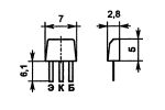
4. Carefully solder Q8 and in its place we solder the good old KT835 from the domestic electronic past, or any other silicon direct conduction transistor. I even ran it with KT361, but did not dare to leave it - you never know ... Yes, I strongly recommend choosing a leak-free transistor.
Click on the image to enlarge
After replacement, there is a 99% chance that your monitor will work. Of course, there may be nuances, but with such symptoms (and they are typical for these monitors), start diagnostics with these details.
Well, for lovers of techno-macro landscapes - a photograph of our transistor KT835, saving foreign infirmities ... 🙂
The article lists the most common monitor breakdowns. One of them is the power supply. Its purpose is to form a stable voltage. At elevated temperatures, electrolytic capacitors "dry out", due to which the voltage becomes unstable or underestimated, which leads to the operation of protection, or a lack of voltage to start. Repair of this malfunction, simple replacement of all "dried" capacitors. Such capacitors are usually swollen. It is worth changing from everything at once, since you come across not bloated, but already losing capacity. This malfunction is not the only one, but it is the most common.
Malfunctions can be expressed as follows:
1. The monitor does not turn on.
2. The monitor turns on for a short time and turns off.
3. There is a whistle-like sound.
Lamp inverter unit.
Most often there are two channels in a lamp inverter. The inverter is powered by a fuse. DC voltage is converted to AC voltage through a generator and transistors. Next is given to the step-up transformer. From it, the voltage goes to the lamps, and to the protection microcircuits.
The reason for the burnout of transistors is poor soldering or fallen off high-voltage capacitors, which are located next to the transistors. Less commonly, transistors burn out due to aging. It is worth ringing the transistors. Each channel has one field-effect transistor. Both transistors must be changed. Because during operation, they change their parameters, and replacing only one transistor, it will be very different from the second, which will lead to overload, and the second (old) will definitely burn out.
Malfunctions can be expressed as follows:
The backlight of the monitor does not turn on for a long time and goes out
When the monitor is turned on, there is no backlight at all.
Control and imaging unit
This block is intended to coordinate all other blocks. The block breaks very rarely and the cause is a "glitch" of the processor. It is treated by warming up the processor to a temperature of 300-400 degrees. It is done by removing the processor from the board and warming up for five or ten minutes, after which it is necessary to solder the processor back.
Malfunctions can be expressed as follows:
There is no image, while the backlight is on.
When the power is turned off, the screen displays “no signal”, and when the power is connected, there is no picture.
The image appears with a low resolution (for example, up to 800x600, while it does not show above).
The exact timing of the repair will become known only during the repair itself. The more serious the breakdown, the longer the repair will take.
- We deliver the equipment to the service center: delivery will arrive to you within an hour
- Defining the problem
- We agree on the price with you: we name the price for repairs + cost of spare parts
- We order spare parts from our warehouse
- Chinim
- We check the quality
After repair, the monitor is tested from 2 to 24 hours, depending on the problem. If the problem persists, the monitor will be repaired again.
We repair all famous brands of monitors: Sony, Samsung, Philips, LG, BenQ, HP and many others.
You can find a complete list of models on this page.
- Stripes, spots, ripples, streaks on the screen
- Broken matrices
- Disassembled monitors
- CRT monitors
- We do not change the stands and legs
You can find out about the geography of our trips here
- LCD display;
- power cable;
- 15-pin VGA video cable;
- Quick Start Guide, Viewsonic Wizard CD-ROM (User / Driver Manual, Multilingual).
- objective testing - studying the color quality of the monitor using the Monaco Optix XR calibrator and determining the uniformity of the backlight and the response time of the monitor in various modes using a specially designed stand;
- subjective testing - an assessment of the color quality and behavior of the monitor in the course of daily work in various real applications (text and graphics editors, DVD movies and dynamic games).
Any product from China "Aliexpress.com" https://ali.pub/uo612
Any product from China “Gearbest.com”
Save on purchases ePN Cashback from 18%
Monitor Repair ViewSonic - VA2248led - VS13818 | An interesting problem.
Hi people. The other day they brought a monitor with a malfunction “The brightness and contrast adjustment menu pops up”, and the monitor may not turn on and the control buttons may not work. After a long search for the defect, a faulty zener diode was found on the display board. The zener diode was replaced with a similar one.
Production Music courtesy of Epidemic Sound!
Hello dear!
Help with the monitor. ViewSonic VA2216W after switching on works normally for an hour - two or less, depending on the heating apparently.
Then, first with a frequency
1 Hz, then more and more often the image briefly changes to a pattern similar to a mattress (when viewed from a distance). 17 vertical stripes with equal white spaces in between. Stripes consist of multi-colored stripes 1 pixel wide, also every 1 pixel. As a result, it seems that gray stripes are blinking. The display time of the image and the mattress becomes the same. For a second of times 3 switches.
If you turn it off for a short time, at least for a second, it does not start blinking immediately, after 5 seconds, just as if you briefly pull out the signal cable.
I tried in the disassembled state the boards were lying on the table - I did not wait for a blink. He warmed the video processor up to 100 - 120 degrees with a hairdryer during operation. The monitor did not start blinking either.
Capacitors seem to be normal, but have not tried to change. Costs?
Tell me where and how to look for an ambush?
In fact, the matrix is faulty and the scaler should not be heated. Ask someone to pick up the hairdryer for a while when you cannot determine the malfunction. Check the operation of the voltage converter on the matrix board.
An interesting observation. The one-color screen does not blink, of any color. Blinking gray and if it is present on the screen in sufficient quantity, and the more of it, the more often it blinks. Although not entirely accurate, white and green can also blink.
Monitor Viewsonic VA1912W after 3 years of work he refused. When turned on, the monitor sensed the computer, that is, there was a signal at the input, but the display remained black.
The likely problem with the monitor is the high voltage part. Let's start disassembling. You can download the service manual here.
Put the monitor with its face on a soft base so as not to damage the screen, then unscrew the 4 screws that hold the leg. Under the leg we will see 2 more screws, by unscrewing them, you can carefully remove the cover and release it from the latches. I will say that the case is made of cheap plastic, so be careful with the latches so as not to break.
Then you should disconnect 4 connectors that supply the matrix luminescent illumination, then 8 more screws and remove the high-voltage block cover.
When checking the circuit 13.8 volts, which just goes through the jumper J204 to the high-voltage transistor of the converter. Firm capacitors CapXon 220μF 25 Volts C204 and C205 turned out to be dry and as a result, the required potential was not supplied to the collector of the Q206 40T03GP transistor.
| Video (click to play). |
Also, through the circuit with C204 and C205, there is a connecting SMD fuse F200 between them. After replacing the capacitors, the monitor worked normally.

