In detail: do-it-yourself Scania injector pump repair from a real master for the site my.housecope.com.
Injector malfunctions can lead to:
- increased fuel consumption;
- the appearance of black smoke;
- a noticeable decrease in power.
Fuel injectors in modern engines require constant attention and proper maintenance.
The main reason for the formation of soot deposits on the sprayer:
- prolonged operation of the internal combustion engine at idle or at low speeds;
- with constant use of the retarder.
Poor fuel quality and poor condition of the fuel filter lead to:
- wear of nozzles;
- violation of the geometry of the conducting channel;
- the appearance on its surface of notches and scoring on the sealed surface.
- repair of the injection pump is needed due to the degree of wear of the plunger pair;
- injectors and fuel filters must be replaced;
- the entire fuel system is being cleaned.
Incorrect injection timing and frequent use of the retarder can cause the spray tip to become very hot. Constant high tip temperature will cause discoloration or bluing of the tip. For this reason, nozzle rejection is not performed, because it does not affect the work of the part.
The content of impurities in the fuel, primarily sulfur and water, causes corrosion of the nozzles. When corrosion occurs:
- cleaning the fuel system;
- check of high pressure fuel pump;
- replacement of nozzles.
Scania's internal combustion engines use three types of injectors, the task of which is to atomize fuel into the combustion chamber:
- single-spring;
- two-spring;
- with a needle movement sensor.
A fuel injection line is used to supply fuel to the injectors.
| Video (click to play). |
Fuel is supplied under pressure to the channel of the rod filter and then to the atomizer through the fuel injection line, which is fixed with a cap nut. The injectors are used with and without a rod filter. The filter is housed in the hollow nozzle body.
Fuel pressure and a spring in the nozzle body cause the nozzle needle to move. The high pressure fuel pump creates the fuel pressure required to raise the nozzle needle. This pressure is called the opening pressure, the lift of the needle is the start of the injection. The atomized fuel enters the combustion chamber through holes that must be precisely calibrated.
The excess fuel, which is formed due to its leakage between the needle and the nozzle body, is removed through the fuel drain line back to the fuel tank. The fuel drain line is connected to the nozzle at the top of it.
1 - injection fuel line from the pump; 2 - cap nut; 3 - rod filter; 4 - drainage fuel line; 5 - spring; 6 - spray needle
The coil of the displacement sensor for this type of injector is located in the holder body. The coil must generate an inductive voltage when the push rod moves upward. The control unit receives a signal via a cable into which the generated inductive voltage is converted.
Fuel is supplied under pressure to the channel of the rod filter and then to the atomizer through the fuel injection line, which is fixed with a cap nut. The injectors are used with and without a rod filter. The filter is housed in the hollow nozzle body.
The spray needle is held pressed against the holder body while the upper spring remains at rest. The upper spring is held by the spring through the push rod and spindle.


1 - injection fuel line from the high pressure fuel pump; 2 - cap nut; 3 - rod filter; 4 - drainage fuel line; 5 - upper spring; 6 - pusher; 7 - bottom spring; 8 - push spindle; 9 - intermediate disc
First stage
The push rod and spindle begin to push the nozzle needle towards the upper spring when the fuel pressure rises. The needle should enter the groove of the intermediate disc with its upper profile, after which the movement of the needle stops. This cycle of movement of the sprayer needle is called pre-lift.
Second stage
The preliminary rise ends when the needle presses the nozzle to the intermediate disc. At this moment, the lower spring is turned on. At idle speed, the first stage of the injector opens. Loads are low and the internal combustion engine is operating at idle speed.
The second stage turns on depending on the loads - to raise the nozzle needle higher, an increase in fuel pressure is required. The spray needle will open a large area for fuel to flow after the pressure reaches the desired level and the needle rises. Increasing loads increases the duration of the injection.
To dismantle the injectors, you must:
- Pre-rinse them in the cylinder head, then dry the surface using compressed air.
- In an internal combustion engine of 12 liters, using a socket wrench 99310, the fuel lines, injection and drainage are removed, then plugs are installed and the rocker arm cover is dismantled.
In an internal combustion engine of 14 liters, the clamps are removed that secure the cable of the injector and the needle movement sensor. Then the switch box cover is dismantled and the С161 / 6 connector is disconnected.
The nozzle is unscrewed using the socket wrench 99308. Care is required when unscrewing the nozzle with the needle movement sensor - do not damage the cable.
To disassemble the injector, an impact mandrel 99 074 is used together with an adapter 99 079.
It is required to check if the seal came out when dismantling the nozzle. If it does not come out, the seal is removed using tool 87 125. A plug must be installed in the nozzle seat.
Attention! To avoid damage to the holes in the spray nozzles, do not use cutting tools, steel wire brushes, brush attachments while working with them. Their use is not possible, because damage to the edge of the holes in the nozzles will cause increased fuel consumption, the appearance of black smoke and a significant decrease in power.
A brass wire brush and cleaning fluids such as white spirit or kerosene are used to clean the outside of the nozzles.
Checking the nozzles on the loading stand
After checking the marking of the nozzle, it is required to check the nozzles on a special stand, type 587 635. The check must be carried out before disassembling the nozzles.
For injectors with two springs, only the first stage is checked.
The injectors are checked on a special stand according to the following parameters:
- lift start pressure;
- working capacity;
- checking the end of injection;
- the quality of the fuel atomization by the sprayer.
The injectors are installed on the internal combustion engine for further use only if satisfactory results are obtained during the check. If such results are not obtained, the injectors need to be repaired or replaced.
Attention! This test may only be carried out in a well-ventilated room. Do not allow sprayed fuel to come into contact with your hands.
The nozzle must be placed in the spray chamber for testing. Then it connects to the load stand. The nut is tightened only after the manometer flap is closed and the calibration oil has not been pumped with the lever to the level of the nut.
The air and dirt from the nozzle is removed by several quick and strong swings.
Functional check
With the manometer shutter open, dry the tip of the sprayer needle. After that, it is required to pump up the pressure, the reference point is to reach a pressure 20 bar lower than the opening pressure.
The achieved pressure level must be maintained for 10 seconds. In a normally operating nozzle, during this time, only the appearance of moisture on the spray tip is allowed and no drops of fuel from the tip are allowed. The defective nozzle must be replaced or treated with paste.
Checking the end of injection
It is required to pump up the pressure to the opening pressure. The time required for the pressure to drop from 100 to 75 bar is then measured.
The normal reading is 6 seconds. If the pressure drop time is less than 6 seconds, the nebulizer is replaced.
For times longer than 25 seconds, the tip of the nebulizer needs to be reworked or replaced.
Checking the needle lift start pressure
It is required to note the pressure of the beginning of the needle rise, for which the load is slowly applied to the stand arm. You need to press the lever until the fuel is released from the sprayer.
Fuel atomization quality check
With the manometer flap closed, you need to make a quick pumping at a speed of 2-3 lever strokes per second. It is required to achieve an even spray of the same shape.
When spraying irregularly shaped, the nozzle is disassembled to clean the spray hole.
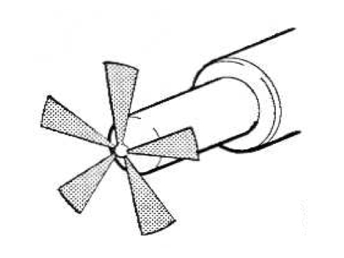

Correct spray pattern
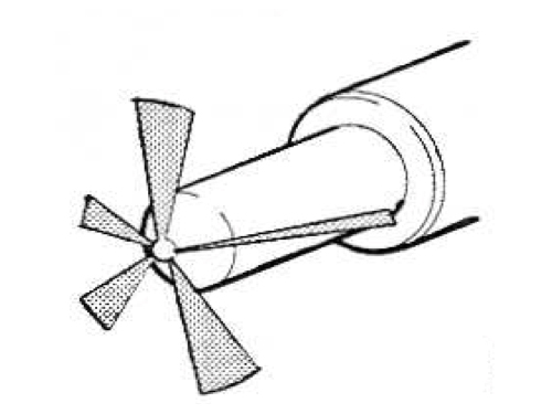


Incorrect spray pattern
Important! It is impossible to install the nozzle needles in other bodies, mixing them. This will compromise the proper fit of the sprayer body and needle. A malfunctioning sprayer in a dual spring nozzle requires replacement of the entire nozzle.
- After fixing the nozzle in the fixture, it is disassembled and cleaned.
- Thick carbon is removed with a liquid that can dissolve it.
- Clean gun body and needle using tool kit 587 179. Brass wire brush may be used. The most effective cleaning method is ultrasonic treatment for 10 minutes. Processing is carried out only by trained specialists on equipment designed for this operation.
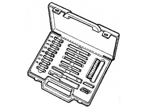

Tool set 587 179 for cleaning the spray gun
Make sure that the diameter of the cleaning needle is 0.03 mm less than the diameter of the spray hole.
The rod filter must be purged. Purging is carried out from the nozzle to the fuel injection line. It is important to ensure that the filter stays in place and does not squeeze out.
Check the quality of cleaning the needle and the nozzle body, the absence of residues of contamination. After this check, the parts are placed in the calibration oil.
The body is installed in a vertical position, with the needle protruding from it by 10 mm. The needle should slide into the body under its own weight. It is required to repeat the operation several times.
Parts must be purged and then lubricated with calibration oil.
Important! To assemble the nozzles and spray guns, use specially made clamping devices. Their use will avoid damage to the injectors. The recommended tightening torques must not be exceeded.
After installing the spray holder into the clamping device, the nozzle is assembled. The spray nut is tightened with force:
Tighten with wrenches 587 071 and 587 673.
After assembly, the start of the needle lift, the operability, the end of the injection and the quality of the fuel atomization by the sprayer are checked.
The sequence of operations when installing injectors:
- The old seal is checked and a new seal is placed on the bottom of the seating surface.
- New seals and O-rings are installed.
- The nozzle fits into the guide groove. The nut is tightened with a force of 70 Nm, a torque wrench and a 99 308 socket are used for tightening.Care is required when tightening the needle displacement nozzle - the cable must not be damaged.
In a 12 liter internal combustion engine, a rocker arm cover is installed, the bolts are tightened with a force of 26 Nm.
In fact, in European car services, no one deals with such labor-intensive trifles as the repair of individual components of any engine or car systems (be it a fuel injection system or another). Block construction means easy replacement, why repair. Does the diagnostic computer indicate injectors? Change - and that's it! And that's right, and everyone agrees. But we are in Russia, and if replacement is an order of magnitude more expensive than repair and there is someone who can perform this repair with high quality, then the carrier will definitely vote for the repair. And this is also correct.
Currently, there are mainly two types of diesel fuel systems in use around the world: pump injectors and the Common-Rail system. For more than ten years now, pump nozzles have been installed on trucks Volvo, Scania, IVECO, which have completely replaced in-line pumps. On "Mercedes" and "Renault" use the Common Rail system.
Recovery technology for unit injectors
For the sake of fairness, we note that engine manufacturers, in particular Volvo, offer services for the restoration of their engines, in particular, pump injectors. Factory overhaul of the unit injector means replacing the atomizer, grinding the plunger and valve bushings. Plungers and valves are put in new, “repair” ones, but these products, unlike sprayers, are not supplied to the secondary market.
Pump-injector in the engine block: 1 - high pressure solenoid valve; 2 - returnable spring; 3 - cylinder head; 4 - pump nozzle body; 5 - high pressure chamber; 6 - sprayer; 7 - rocker; 8 - drive cam; 9 - clamping bracket; 10 - fuel backflow channel; 11 - fuel supply channel; 12 - spray nut; 13 - engine valve.
The cavities of the unit injectors are constantly filled with fuel supplied from the tank under a pressure of about 5-6 atm. At the moment corresponding to the intake stroke, the control unit sends a signal to the solenoid valve, the fuel supply from the tank is cut off. The rocker pushes the plunger, the plunger creates pressure (about 1500 kg / cm 2) in the high-pressure chamber. This pressure opens the nozzle and injects fuel into the cylinder. In case of wear of the nozzle (increase in the diameter of the holes in it), the nozzle “overflows”. A worn-out valve does not "hold" the pressure, the fuel, accordingly, goes back to the supply line, instead of being compressed into the cylinder. A worn plunger is simply unable to generate sufficient injection pressure. That's all the defects. In the overwhelming majority of cases, they are removable.
Alexander Sorokin, drawing by Victoria Poverenova
Bosch pump injector repair video
The video about the repair of Bosch unit injectors was filmed by the specialists of the diesel service LuganskTrakService in the city of Lugansk. Unfortunately, there is a video with ads, but it can be turned off after 10s.
Delphi Service Is a time-tested company. We have been working in the market of automobile services in the city of Samara for over 7 years. Repair quality in Delphi Service confirmed not only by the positive reviews of our clients, but also by the received certificate DELPHI DIESEL Service ... We received this document from an English company DELPHI.
The center is able to repair the following fuel supply systems:
- Repair of DAF XF 105 injectors;
- Repair of pump injectors DELPHI and BOSCH;
- Repair of pumping sections DELPHI and BOSCH;
- Repair of BOSCH Common Rail injectors;
- Repair of DELPHI Common Rail injectors;
- DENSO Common Rail injectors check;
- BOSCH injection pump repair.
This certificate gives us the official right to repair and service fuel equipment DAF XF 105 with pump nozzles and smart nozzles DAF XF 105 | CF 85.
Using equipment for checking injectors and pump injectors HARTRIDGE AVM2 PC also gives us the opportunity to assign a new code after repairing injectors and pump sections.
Volvo, Scania and Iveco trucks are most often assembled in factories using pump nozzles.
DELPHI Service apply for maintenance and repair of the BOSCH Common Rail fuel system. This system is presented on the market by RENO and MAN trucks. The Cummins series is actively used by Russian, Korean and Chinese car manufacturers. So you can find the following cars with a Cummins engine: KAMAZ; GROOVE; GAS; FAW; Valdai; BAF; Gazelle; DongFeng; Shaanxi; Shakman;
DELPHI Common Rail fuel systems are preferred by Korean manufacturers HYUNDAI, SsangYong, KIA.
Individual fuel pumps (PLD pump sections) are also used in truck assembly. Fuel pumps are very popular among the following brands: DAF; RENAULT; Mercedes; Deutz.
V DELPHI Service we also provide diagnostics for Denso Common Rail systems. Passenger cars of Asian production TOYOTA, NISSAN, ISUZU, MITSUBISHI mainly operate on the DENSO lonely system.
Common rail systems DELPHI are fully refurbished. An important point in the repair of DELPHI injectors is the assignment of a new code, otherwise one cannot count on the correct operation of the injector. DELPHI common injectors are more often used on European machines PEUGEOT, CITROEN, FIAT, FORD, OPEL, RENO. DELPHI fuel systems are more and more often used by Korean manufacturers of light vehicles such as HYUNDAI, SsangYong, KIA.
Happy Scania owners are here
Message Gogole »04 Aug 2014, 17:05
Troit scan with PDE fuel. The service said replacement nozzles, all 6 pieces. Even beyond repair. How can this be all at once! and can't be repaired right away? Consumption was normal, and podtraival periodically. We connected a computer in our garage. The imbalance of the injectors was of course very spooky. The balancing operation took place only 3 times. (2 times on the 3rd cylinder it broke off) It seems that everything became normal, and then I spent it again. Maybe there are some other nuances in this fuel.
And yet, since any PDE can be changed so well, or how are there several varieties of them in HPI? There is a parsing force 1529749/1497364 DSC1205 vin 9053062 and will they fit 1440580 DC 12 01/09/16 vin 4512236.
Message POIKO »04 Aug 2014, 17:42
Message Polosukhin Roman »04 Aug 2014, 20:43
Message sereschka »04 Aug 2014, 21:58
Injector malfunctions can lead to:
- increased fuel consumption;
- the appearance of black smoke;
- a noticeable decrease in power.
Fuel injectors in modern engines require constant attention and proper maintenance.
The main reason for the formation of soot deposits on the sprayer:
- prolonged operation of the internal combustion engine at idle or at low speeds;
- with constant use of the retarder.
Poor fuel quality and poor condition of the fuel filter lead to:
- wear of nozzles;
- violation of the geometry of the conducting channel;
- the appearance on its surface of notches and scoring on the sealed surface.
- repair of the injection pump is needed due to the degree of wear of the plunger pair;
- injectors and fuel filters must be replaced;
- the entire fuel system is being cleaned.
Incorrect injection timing and frequent use of the retarder can cause the spray tip to become very hot. Constant high tip temperature will cause discoloration or bluing of the tip. For this reason, nozzle rejection is not performed, because it does not affect the work of the part.
The content of impurities in the fuel, primarily sulfur and water, causes corrosion of the nozzles. When corrosion occurs:
- cleaning the fuel system;
- check of high pressure fuel pump;
- replacement of nozzles.
Scania's internal combustion engines use three types of injectors, the task of which is to atomize fuel into the combustion chamber:
- single-spring;
- two-spring;
- with a needle movement sensor.
A fuel injection line is used to supply fuel to the injectors.
Fuel is supplied under pressure to the channel of the rod filter and then to the atomizer through the fuel injection line, which is fixed with a cap nut. The injectors are used with and without a rod filter. The filter is housed in the hollow nozzle body.
Fuel pressure and a spring in the nozzle body cause the nozzle needle to move. The high pressure fuel pump creates the fuel pressure required to raise the nozzle needle. This pressure is called the opening pressure, the lift of the needle is the start of the injection. The atomized fuel enters the combustion chamber through holes that must be precisely calibrated.
The excess fuel, which is formed due to its leakage between the needle and the nozzle body, is removed through the fuel drain line back to the fuel tank. The fuel drain line is connected to the nozzle at the top of it.


1 - injection fuel line from the pump; 2 - cap nut; 3 - rod filter; 4 - drainage fuel line; 5 - spring; 6 - spray needle
The coil of the displacement sensor for this type of injector is located in the holder body. The coil must generate an inductive voltage when the push rod moves upward. The control unit receives a signal via a cable into which the generated inductive voltage is converted.
Fuel is supplied under pressure to the channel of the rod filter and then to the atomizer through the fuel injection line, which is fixed with a cap nut. The injectors are used with and without a rod filter. The filter is housed in the hollow nozzle body.
The spray needle is held pressed against the holder body while the upper spring remains at rest. The upper spring is held by the spring through the push rod and spindle.


1 - injection fuel line from the high pressure fuel pump; 2 - cap nut; 3 - rod filter; 4 - drainage fuel line; 5 - upper spring; 6 - pusher; 7 - bottom spring; 8 - push spindle; 9 - intermediate disc
First stage
The push rod and spindle begin to push the nozzle needle towards the upper spring when the fuel pressure rises. The needle should enter the groove of the intermediate disc with its upper profile, after which the movement of the needle stops. This cycle of movement of the sprayer needle is called pre-lift.
Second stage
The preliminary rise ends when the needle presses the nozzle to the intermediate disc. At this moment, the lower spring is turned on. At idle speed, the first stage of the injector opens. Loads are low and the internal combustion engine is operating at idle speed.
The second stage turns on depending on the loads - to raise the nozzle needle higher, an increase in fuel pressure is required. The spray needle will open a large area for fuel to flow after the pressure reaches the desired level and the needle rises. Increasing loads increases the duration of the injection.
To dismantle the injectors, you must:
- Pre-rinse them in the cylinder head, then dry the surface using compressed air.
- In an internal combustion engine of 12 liters, using a socket wrench 99310, the fuel lines, injection and drainage are removed, then plugs are installed and the rocker arm cover is dismantled.
In an internal combustion engine of 14 liters, the clamps are removed that secure the cable of the injector and the needle movement sensor. Then the switch box cover is dismantled and the С161 / 6 connector is disconnected.
The nozzle is unscrewed using the socket wrench 99308. Care is required when unscrewing the nozzle with the needle movement sensor - do not damage the cable.
To disassemble the injector, an impact mandrel 99 074 is used together with an adapter 99 079.
It is required to check if the seal came out when dismantling the nozzle.If it does not come out, the seal is removed using tool 87 125. A plug must be installed in the nozzle seat.
Attention! To avoid damage to the holes in the spray nozzles, do not use cutting tools, steel wire brushes, brush attachments while working with them. Their use is not possible, because damage to the edge of the holes in the nozzles will cause increased fuel consumption, the appearance of black smoke and a significant decrease in power.
A brass wire brush and cleaning fluids such as white spirit or kerosene are used to clean the outside of the nozzles.
Checking the nozzles on the loading stand
After checking the marking of the nozzle, it is required to check the nozzles on a special stand, type 587 635. The check must be carried out before disassembling the nozzles.
For injectors with two springs, only the first stage is checked.
The injectors are checked on a special stand according to the following parameters:
- lift start pressure;
- working capacity;
- checking the end of injection;
- the quality of the fuel atomization by the sprayer.
The injectors are installed on the internal combustion engine for further use only if satisfactory results are obtained during the check. If such results are not obtained, the injectors need to be repaired or replaced.
Attention! This test may only be carried out in a well-ventilated room. Do not allow sprayed fuel to come into contact with your hands.
The nozzle must be placed in the spray chamber for testing. Then it connects to the load stand. The nut is tightened only after the manometer flap is closed and the calibration oil has not been pumped with the lever to the level of the nut.
The air and dirt from the nozzle is removed by several quick and strong swings.
Functional check
With the manometer shutter open, dry the tip of the sprayer needle. After that, it is required to pump up the pressure, the reference point is to reach a pressure 20 bar lower than the opening pressure.
The achieved pressure level must be maintained for 10 seconds. In a normally operating nozzle, during this time, only the appearance of moisture on the spray tip is allowed and no drops of fuel from the tip are allowed. The defective nozzle must be replaced or treated with paste.
Checking the end of injection
It is required to pump up the pressure to the opening pressure. The time required for the pressure to drop from 100 to 75 bar is then measured.
The normal reading is 6 seconds. If the pressure drop time is less than 6 seconds, the nebulizer is replaced.
For times longer than 25 seconds, the tip of the nebulizer needs to be reworked or replaced.
Checking the needle lift start pressure
It is required to note the pressure of the beginning of the needle rise, for which the load is slowly applied to the stand arm. You need to press the lever until the fuel is released from the sprayer.
Fuel atomization quality check
With the manometer flap closed, you need to make a quick pumping at a speed of 2-3 lever strokes per second. It is required to achieve an even spray of the same shape.
When spraying irregularly shaped, the nozzle is disassembled to clean the spray hole.


Correct spray pattern


Incorrect spray pattern
Important! It is impossible to install the nozzle needles in other bodies, mixing them. This will compromise the proper fit of the sprayer body and needle. A malfunctioning sprayer in a dual spring nozzle requires replacement of the entire nozzle.
- After fixing the nozzle in the fixture, it is disassembled and cleaned.
- Thick carbon is removed with a liquid that can dissolve it.
- Clean gun body and needle using tool kit 587 179. Brass wire brush may be used. The most effective cleaning method is ultrasonic treatment for 10 minutes.Processing is carried out only by trained specialists on equipment designed for this operation.


Tool set 587 179 for cleaning the spray gun
Make sure that the diameter of the cleaning needle is 0.03 mm less than the diameter of the spray hole.
The rod filter must be purged. Purging is carried out from the nozzle to the fuel injection line. It is important to ensure that the filter stays in place and does not squeeze out.
Check the quality of cleaning the needle and the nozzle body, the absence of residues of contamination. After this check, the parts are placed in the calibration oil.
The body is installed in a vertical position, with the needle protruding from it by 10 mm. The needle should slide into the body under its own weight. It is required to repeat the operation several times.
Parts must be purged and then lubricated with calibration oil.
Important! To assemble the nozzles and spray guns, use specially made clamping devices. Their use will avoid damage to the injectors. The recommended tightening torques must not be exceeded.
After installing the spray holder into the clamping device, the nozzle is assembled. The spray nut is tightened with force:
Tighten with wrenches 587 071 and 587 673.
After assembly, the start of the needle lift, the operability, the end of the injection and the quality of the fuel atomization by the sprayer are checked.
The sequence of operations when installing injectors:
- The old seal is checked and a new seal is placed on the bottom of the seating surface.
- New seals and O-rings are installed.
- The nozzle fits into the guide groove. The nut is tightened with a force of 70 Nm, a torque wrench and a tip 99 308 are used for tightening. Care is required when tightening the nozzle with the needle movement sensor - the cable must not be damaged.
In a 12 liter internal combustion engine, a rocker arm cover is installed, the bolts are tightened with a force of 26 Nm.
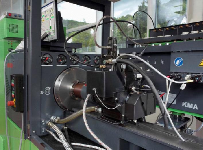
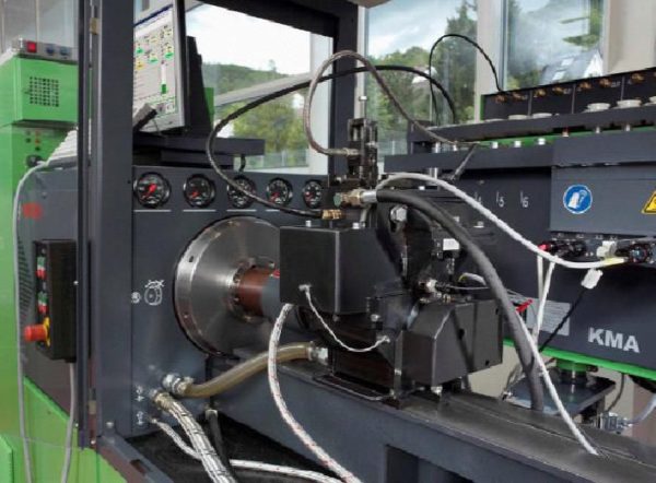
Malfunctions typically occur in only one cylinder, allowing the truck or bus to stay on track. The computer will simply disconnect the broken injector from the system, and you will reach your destination without any problems. However, this does not mean that if a problem is found, the repair of the Scania pump injectors can be postponed indefinitely. On the contrary, the sooner you arrive at the service center, the higher the likelihood that you will be able to do without major repairs associated with a completely different order of costs.
Here are the signs that indicate a problem with the Scania unit injectors. The first of these is the triplet engine. This malfunction, among other things, can lead to mechanical wear of the sprayer or valve assembly, failure of the electromagnet or an open circuit.
In addition, you should be alert if the engine consumes too much fuel at normal thrust, or thick black smoke is pouring out of the exhaust pipe. As a rule, such problems are caused by a hole in the sprayer, which has undergone wear over time.Somewhat less often, excessive fuel consumption indicates total wear of all components of the injector - in this case, the only way out is to completely replace this element of the fuel system.
Finally, if the engine trots and smokes so much that it seems to be about to explode, a possible cause is a malfunction of the pump nozzle atomizer. This part is the most vulnerable in the nozzle and at the same time it is more exposed to wear than other elements of the system.
Repair of pump injectors Scania always begins with identifying the nature and severity of damage. For this purpose, diagnostics are carried out at a special stand, according to the results of which the masters repair or replace the worn out part. It is usually recommended to replace a complete set of injectors at once so that they all have the same service life. Upon completion of the repair measures, the unit injector undergoes repeated tests at the stand, after which the specialists adjust the parameters of its performance.
Scania was founded in 1891. Since then, the company has produced and delivered more than 1,400 thousand trucks and buses for work in all countries of the world.
Even in times of crisis in the truck market, Scania has always shown good profit margins on truck and bus sales. During this time, Scania diesel engines have proven their reliability and quality, operating in tough conditions around the world.
Scania is manufactured in eleven factories in five countries.
Scania manufactures trucks, buses, marine and diesel engines. The company also supplies its chassis to many third-party body shops.
In 2004 and 2009, Scania's R-series trucks were honored with the prestigious international Truck of the Year award.
Scania today produces a large number of trucks and is a leader in the design and manufacture of heavy duty vehicles.
Scania diesels have a high level of quality and reliability, and the number of versions depends on the purpose and operating conditions of machines and mechanisms.
Delfidizelservice repairs Scania pump injectors installed on diesel engines: special equipment, low-tonnage vehicles, auto transporters, mainline tractors and buses. Scania equips trucks with turbocharged and intercooled diesel engines. Modern Scania diesels are equipped with a Cummins pump injector fuel system, which we successfully repair.
In the authorized service center of Eurodiesel Center LLC, car owners always receive professional and high-quality repairs of modern pump injectors Kamins of diesel power plants installed on the latest Scania HPI models.
| Video (click to play). |
Scania repair is carried out at specialized computer stands by trained personnel, which allows us to guarantee high-quality scan engine repair. Repairing a Scania truck in our workshop always starts with a complete vehicle diagnosis. Our Scania Service Station is a specialized Scania repair service equipped with the latest equipment, technology and technical documentation for Scania engine repair. Engineers and mechanics of the company are engaged in the repair of Scania on a professional basis, and Scania HPI diesels are one of the main areas of repair of our hundred.After repair, the technical and dynamic characteristics of the Scania truck meet all European quality standards and environmental standards. Reducing fuel consumption after repairing the Scania engine is confirmed by dynamic engine tests. A full complex of computer diagnostics Scania eliminates errors in the repair of Scania diesel engines.


