In detail: do-it-yourself repair of the front axle of the UAZ 3303 from a real master for the site my.housecope.com.
The front axle of the car UAZ-3303, UAZ-3909, 2206 is the leading one. The crankcase, final drive and differential of the front axle do not differ from the corresponding parts and assemblies of the rear axle.
All operations of disassembly, assembly, maintenance, adjustment and possible malfunctions are the same as for the rear axle.
The steering knuckle device of the front drive axle UAZ-3303, UAZ-3909, 2206 is shown in Fig. one.
To the casing 2 of the axle shaft, a ball bearing 6 with 30 pivot pins pressed into it is fastened with five bolts.
A steering knuckle body 7 is installed on a ball bearing with the help of two pivots 9.
Rice. 1. Steering knuckle of the front drive axle UAZ-3909, UAZ-2206, 3303
I - right swivel knuckle; II - left swivel fist; III - wheel disconnect clutch; a - signal groove; IV - wheel disconnect clutch; b - pointer; 1 - steering knuckle pad; 2 - half-axle casing; 3.27 - cuffs; 4 - bipod pull; 5 - gasket; 6 - ball joint; 7 - steering knuckle body; 8 - steering knuckle lever; 9 - kingpin; 10 -press grease can; 11 - locking pin; 12 - retaining rings; 13 -tap; 14 - wheel hub; 15 - gasket; 16-lock washer; 17 - leading flange; 18 - clutch; 19 - clutch bolt; 20 - retainer ball; 21 - protective cap; 22 - nuts; 23 -bolt; 24 - persistent washer; 25 - hub bearings; 26 - spacer ring; 28 - bottom overlay; 29 - support washer; 30 - kingpin bushing; 31 - adjusting gaskets; 32 - inner gland holder; 33 - partition ring; 34 - outer gland holder; 35 - inner sealing ring; 36 - outer sealing ring; 37 - persistent washers; 38 - hinge; 39 - bolt of rotation limitation; 40-stop-limiter for turning wheels; 41-steering rod; 42-disc wheel clutch
| Video (click to play). |
The steering knuckle pins are installed with a preload along their common axis, the value of which is 0.02-0.10 mm.
From turning in the steering knuckle housing, the pins are locked with pins 11.
Adjust the preload with shims 31 installed at the top - between the steering knuckle lever (left) 8 or overlay (right) 1 and the steering knuckle housing, at the bottom - between the linings and the steering knuckle housing.
To lubricate the upper pivots and add lubricant to the ball joint, grease fittings 10 are installed on the steering knuckle arm of the UAZ-3303, UAZ-3909, 2206 (left) and on the upper pad of the kingpin (right).
The lower pivots are lubricated with grease coming by gravity from the ball joint.
Inside the steering knuckle of the front axle of the UAZ-3303, UAZ-3909, 2206, a constant velocity joint (CV joint) is installed.
The design of the hinge ensures the same angular velocities of the driving and driven shafts, regardless of the angle between them.
The hinge consists of two forks with four balls in the curved grooves.
The fifth ball is located in the central sockets of the forks, which is a locating one and serves for centering the forks.
From longitudinal movement, the hinge is limited by a thrust washer 3 7.
The inner drive hinge fork is spline-connected to the differential side gear.
At the driven end of the hinge knuckle there is a device for disengaging the front wheels, which consists of a movable clutch 18 mounted on the splines and a bolt 19 with a spring and a ball.
The outer splines of the movable clutch are connected to the inner splines of the driving flange 17, which is bolted to the wheel hub.
To reduce the wear of parts of the front drive axle UAZ-3909, UAZ-2206, 3303 and save fuel when operating a car on paved roads, it is advisable to disconnect the front wheel hubs together with turning off the front drive axle.
To do this, remove the protective cap 21 and, by unscrewing the bolt 19, set the coupling to the position where the signal annular groove “a” on its surface is located in the same plane with the flange face.
After setting the coupling in the required position, screw on the protective cap.
Turn on the wheel by screwing bolt 19 with a secure tightening. On some cars, it is possible to install a front wheel cut-off clutch, shown in Fig. 1- IV.
To disengage the wheels, it is necessary to turn the disc 42 of the clutch counterclockwise until it stops, while aligning the pointer “b” with the inscription “4 × 2”.
Switch on by turning the disc clockwise until it stops, aligning the pointer with the inscription “4 × 4”.
Engage and deactivate operations on both wheels of the front drive axle.
Maintenance of the front axle UAZ-3303, UAZ-3909, 2206
When inspecting the steering knuckles of the front axle of the UAZ-3303, UAZ-3909, 2206, pay attention to the serviceability of the adjusting bolts 39, stop-stops 40 for wheel rotation and the reliability of their locking.
The angle of rotation of the right wheel - to the right, and the left - to the left should be no more than 27 °. The increased angle of rotation of the wheels leads to the destruction of the steering knuckle joints.
Adjustment of the tightening of the pivots of the steering knuckle UAZ-3303, UAZ-3909, 2206 at the factory is carried out with a preload along their common axis, and the same number of spacers 31 are installed above and below.
With the wear of the rubbing surfaces, the preload disappears and an axial gap is formed between the ends of the pivots 9 and the support rings of the ball bearing 6.
Remove this gap by removing the same number of shims 31 from above and below.
The difference between the total thicknesses of the upper and lower spacers should not exceed 0.1 mm.
Carry out wheel alignment adjustment at normal tire pressure in such a way that the size measured along the centerline of the side surface of the tires in front is 1.5-3.0 mm less than the size at the rear.
Check toe-in of wheels on the outer or inner surfaces of the tires.
Check the convergence on the outer surfaces at a special stand. At the same time, find the points of equal lateral runout of the tires and arrange them in the horizontal plane.
Otherwise, due to significant lateral runout of the tires, the toe-in will be incorrectly adjusted.
Determination of toe-in of wheels on the inner surfaces of tires should be carried out in the absence of a special stand.
Install the UAZ-2206, UAZ-3909, 3303 vehicle on the inspection pit with the wheels positioned for straight-ahead driving.
Using a rod with a movable ruler, measure the distance between the inner surfaces of the tires at the rear, approximately at the height of the center of the wheel.
In this case, set the bar horizontally, and mark the points of contact between the bar and the tires with chalk.
Then roll the car forward or backward by such an amount that the points marked on the tires are at the front at the same height, and the measurement between the marked points is repeated.
Rice. 2. Draft steering linkage UAZ-3303, UAZ-3909, 2206
1 - lock nut with left-hand thread; 2 - adjusting fitting; 3 - lock nut with right-hand thread; 4-hinge
The difference between the first and second measurements is the toe-in value.
If necessary, adjust the wheel toe-in by changing the length of the steering linkage by rotating the union 2 (Fig. 2) after first loosening the locknuts 1 and 3 with left and right threads. Tighten the locknuts after adjusting.
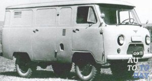
UAZ 3741 is a four-wheel drive domestic utility vehicle, produced in Soviet times under the symbol UAZ 452. For its characteristic body shape, it received the popular nickname “loaf”. In the factory configuration, it has an all-metal body, leaf spring suspension and 2 drive axles with non-locking differentials that transmit power to all 4 wheels.
Rear-wheel drive is permanent, front-wheel drive is plug-in. The bridges are unified with the UAZ 31512. Carrying capacity - 850 kg. Clearance - 220 mm. Repair of the front axle of the UAZ 3741 is extremely rare, since its design is quite reliable. Basically, it all comes down to replacing the wheel bearings and oil in the differential, ball and pivot pins. But sometimes it is necessary to remove the bridge. And you have to do it yourself, since UAZ service centers are far from everywhere.
Since the UAZ 3741 has a frame structure, it is quite easy to remove the front axle. To do this, you need to stock up on a powerful jack, stops that can withstand 1.5 tons of the weight of the front of the car, and a special liquid for unscrewing the nuts - WD-40.
- First, you need to substitute stops under the rear wheels.
- Then you need to disconnect the right and left brake pipes from the rubber hoses that go to the front wheel brake drums.
- After that, unscrew the nuts securing the brake hoses and remove the hoses themselves.
- Next, you need to unscrew the nuts that secure the lower ends of the shock absorbers.
- After that, it is necessary to unscrew the bolts connecting the front universal joint with the drive pinion flange.
- Then you should unpin and unscrew the nut of the ball pin of the bipod.
- Next, you need to disconnect the rod from the bipod.
- Now you need to unscrew the nuts securing the stepladders of the front springs, remove the stepladders along with the linings and linings.
- At the end, lift the front of the car by the frame and pull the axle out from under the car.
After the old bridge has been removed, you can proceed with the installation of the new part by performing the steps in reverse order. If necessary, the removed unit is disassembled, troubleshooting is carried out, damaged parts are replaced and the bridge is installed back.
The most common reason for the inappropriate behavior of the UAZ 3741 vehicle on the road is the violation of the axial clearance of the pivots. It is very simple to check whether it is broken or not - just raise the front end with a jack and try to swing the wheel up and down. If end play exists, the pivot clearance should be adjusted.
The adjustment is carried out as follows.
- We raise the front of the car, having previously put the car on the handbrake.
- We dismantle the wheel.
- We unscrew the bolts securing the ball seal.
- We check the axial play by shaking the structure up and down with our hands.
- We unscrew several bolts securing the upper lining of the king pin. Remove the cover.
- We take out the thinnest shim and put the pad back.
- We carry out the same procedures with the lower pad of the king pin.
- We tighten all the bolts and check the result. If the backlash is eliminated, screw the oil seal and the wheel back on and go. If the backlash remains, we adjust everything again, this time removing the thicker gaskets.
It is important to pull out equally thick spacers at both the top and bottom to maintain the alignment of the CV joint. If the alignment is broken, expensive repairs will have to be done after a while.
Camshaft (new). Made of cast iron, these camshafts are available for ZMZ-402 engines. There are two reasons for using it. Bleached cast iron has a very high hardness and corresponding wear resistance. But the main reason is that the cams of this shaft are made with a steeper profile compared to the UAZ camshaft, and at the same time, naturally, the filling of the cylinders is improved.
Engine block. Apparently, “in search of pressure,” the nuts on the covers of the main bearing beds were tightened so that the covers were pressed into the block by a few tenths of a millimeter. And, as a result, the inserts pushed the beds themselves. And when, in all likelihood, they found that the shaft was not "tossing and turning", they put brackets under the covers. This, yes, plus, a worn-out oil pump, is the explanation of the pressure riddle.
Rear axle (new), both axle shafts were set in the lathe, in the centers, the fender mating plane with the hub, on the left axle shaft, had practically no beats. And on the right one there were beats of 0.3 mm, by means of simple mathematical calculations, you can find out what beats will be at the end of the semi-axis, if its length is 650 mm, the diameter of the flange is 100 mm, and mentally imagine what stresses the semi-axis undergoes, rigidly fixed at both ends.
If these planes of the semiaxes are not corrected, then one of the "sores" of the UAZ will certainly appear; the tightening of the bolts and securing the axle shafts will be constantly loosened. In order to finally get away from this problem, on the hubs of the front and rear axles, in place of the standard bolts, we used studs with a standard thread on one side and with a thread with a pitch of 1.25 mm on the other.
Nuts with a thread with a pitch of 1.25 mm, had to be applied, on a 15 mm wrench, and then when tightening, the edges of the nuts must be oriented tangentially to the circumference of the hub, otherwise the wheel disks do not pass.
Differential bearings, had to be adjusted again, were overtightened, as well as on the front axle.
Two more brackets were welded to the rear axle for additional shock absorbers.
Gearbox (new) synchronized on all four gears. When, after the purchase, we opened the gearbox cover, we were pleasantly surprised, this is a fundamentally new unit, (our "Russians" can do "things").
By the standards of the old box, huge synchronizers, reinforced gears, and intuitively, I liked the box very much. But these are emotions, further operation will show how good it is, but for now, I enjoy driving a car, without overgasm.
Transfer case (new), the same as it was, there is nothing to choose from, although there is, the first "razdatka" that was purchased, had to be exchanged, a tooth, some kind of gear was not cut radially, hence there were jamming. And when the flange of the rear axle cardan was removed from the exchanged "hand-out", the oil seal spring was found inside the box, at first they thought that it had slipped off the oil seal, but when they opened the back cover, they saw that the spring at the oil seal was in place.
Apparently, the "caring" manufacturers put in a "spare". If it gets into the cavity of the box, there could be trouble.
The threads were cut in the block, for the head mounting studs, with a diameter of 12 mm. With standard eleven-millimeter ones, with a step of 1 mm, it is impossible to normally stretch the block head. Washers for this interface were made of steel 40 XH, 5mm thick and 26mm outer diameter. Moreover, they are used without any preliminary heat treatment. The holes for the studs in the block head were bored to 13 mm.
Bolts with a diameter of 10 mm, with a standard thread, for fastening the flywheel casing and engine support legs, were made of bolts, fastening the block bed covers, VAZ cars. From under the standard ones, with 14 mm heads, when broaching, squeezes the grover washers. (I must say, this drawback manifests itself on all UAZ units, therefore, it was made for a dozen of such bolts.)
Engine suspension. Instead of the front, standard, engine mountings, pillows from the GAZ-3102 were used. The vibration transmitted from the engine to the frame has been drastically reduced. In the future, I'm going to remake the rear suspension units, but at the same time, I will have to install two longitudinal jet rods, so that, with sharp braking, the engine will not shift forward.
Pump (water pump). The housing, bored for the installation, of two 603 bearings, after boring it was put on a mandrel, and all the fender flats were corrected, especially this relates to the plane of interface with the oil seal, it must also be polished.
The impeller blades were welded in height and ground to a clearance between them and the cover plane, 0.5 mm.
The pump pulley was made anew, with a diameter of 100 mm and for two belts, the crankshaft pulley with a diameter of 160 mm was similarly made. The fact is that for the normal operation of the 1000 watt generator, which we used, one belt is not enough.
And one more goal that we pursued, changing the diameters of the pulleys, is to increase the speed of the pump and, accordingly, the fan, to increase the efficiency of the cooling and heating systems.
Brake system. What was modified in it was a vacuum amplifier was installed (it was not there before the repair) and instead of the standard working cylinders, self-diluting "Volgovskiye" were used.
As I mentioned earlier, the brake drums were machined. After this minimum of modifications, the brakes became just a "fairy tale".
Gas drive. In the engine power system, a K-151 carburetor was used, so it was decided to perform the drive with a cable. This made it possible to remove backlash in the gas drive and get rid of the "heap of unnecessary pieces of iron".
On the wall itself, a stop was fixed, under the bowden of the cable and an adjusting screw of the return spring.
On the carburetor mounting studs, a homemade bracket with an emphasis was installed, similar to the "Volgovsky".
The use of pulleys in the gas drive gave a linear relationship between the deflection of the gas pedal and the opening of the carburetor throttle valves, plus the smoothness and softness of the gas pedal stroke.
Air filter. The filter element, due to the very limited space of the engine compartment, used a flat, square shape. They are produced for injection engines, VAZ cars. Despite their compactness, they have high filtering properties and low resistance to air flow.
The filter housing was made with a common platform for the carburetor and the filter element, so that the filter element stood above the valve cover. The air flow into the filter is directed from the bottom along the engine, thereby solving the problem with heating the intake air. The only thing that had to be redone in this case was the engine bonnet hinges.
Control mechanism, gearbox.
With a slightly increased effort on the gear lever, this gave a very noticeable decrease in its travel, and since the adjustment limits have not a bad range, it became possible to adjust the position of the lever so that the control of the gearbox becomes quite comfortable.
Of course, when you have to be behind the wheel of a car for a very long time, along with reliability and safety, the question of ease of use arises, and this question develops from a whole complex of conditions. Quite a large part of them, we were able to implement, based on our own experience, something, we simply could not foresee, and something remained unfulfilled due to a lack of finances and time. And so on, what we managed to bring to life.
Heating system. The van is heated by a heater, based on a four-row UAZ radiator, involved in two strokes, i.e. the air flow to the "suction" fan enters through one half, and from the "pressure" of the fan passes through the other. The cabin is warm enough, but in the future it is planned to heat the van, with an external air intake, in order to ventilate the cabin.
In the cab, a heater from a GAZ-3307 car is installed, made in a plastic case, based on a radiator similar to a heater radiator for VAZ cars of a classic layout. With two centrifugal fans, it cannot be compared with the standard heater of the UAZ, which, with its “deceptive” axial fan, can hardly be called anything else other than a mockery.
In order for the two heaters not to mutually interfere with each other's work, two separate radiator power loops were created. The direct branch of the cab heater power supply is connected as standard, i.e. from above, into the block head, above the fourth cylinder.
The power supply for the radiator of the "stove" of the van is carried out somewhat differently. Straight branch, connected to a nipple screwed into a cover mounted on the back of the block head, instead of a metal plug. "Return", to the tee cut into the return branch of the cooling radiator.
Also, in the heating system, there are fittings for connecting an autonomous antifreeze heater, the heater itself is available and checked at the stand, but has not yet been installed.
The front suspension has not undergone any changes, except that one more leaf has been added to the springs.
I must say that when the car was dismantled before being repaired, it was discovered that there were springs on the front suspension; on the left side 13 and on the right 14 sheets. The springs on the rear suspension were similarly, only for a turn; from the left 14 and from the right 13 sheets.
Shock absorbers for UAZ, it is better to use family, double-acting, they work much more efficiently single-acting shock absorbers, Gazelle cars and the like.
Steering. While it has remained unchanged, of course, there is a temptation to establish a power steering, but there is also a question of financial problems, in general, this question is still open.
Electrical equipment... If you describe what has been done and what else is planned, it will be a very large volume, since this topic concerns a lot, from mechanics to electronics.
Therefore, I will briefly describe the main change; in place of the standard one, a 90-ampere generator and two batteries were installed (one as a standard one for the operation of the car's electrical equipment, the second for ensuring the start-up and operation of the antifreeze heater and as a power source for country trips). The generator is larger than the standard one, so 1100 mm belts had to be used.
Lubrication. After running-in, any high-quality oil, up to synthetic oil, can be poured into the engine lubrication system, depending on climatic conditions and material condition. But it must be remembered that the better the oil is used, the greater the engine "mileage" to the cap. repair, and these are already incommensurable costs in comparison with the price, even of the most expensive oil.
The same applies to the transmission, i.e. the better the oil is poured into the bridges and boxes, the more they "come out".
But for the lubrication of CV joints and wheel hubs, we used specially prepared oil mixtures. The knuckles were packed with a mixture of equal weight proportions; SHRUS grease, KONSOL firm and TC-p10 transmission oil.
In the wheel hubs, in the corner of the shoulder of the seats, under the brake drum, and the wheel disc, holes were drilled, with an inclination of about 45 degrees, and an M-6 thread was cut for the syringe fitting and the plug. After adjusting the bearings to dry, through these holes, inside the hub, a mixture of "Litola" and TC-p10 was pressed in, the same in equal proportions.
Body, Salon
Reutov Konstantin Borisovich aka [skdingo]
Russia, Krasnoyarsk kr.
Kansk
Hello everyone. Today I finally decided to repair the front axle. As I wrote in the first snow, I had to turn on the front axle, also for the first time.
It crunched and at times even jammed the right side, when cornering so that the steering wheel was knocked out of the hands, somehow I got to the city.
Dismantled the right side, almost all.When I removed the CV joint, the balls were all scattered throughout the steering knuckle, naturally it will wedge.
I thought that it would not be as easy to disassemble it as always. It turned out to be the other way around, it couldn't be easier, everything went smoothly, thank God. Now we have to purchase gaskets, sleeping bags, and the assembly.
Please help me figure it out. The question is for those who understand and understand, is it necessary to buy a new CV joint or not? Why are balls flying out?
Good luck to all.
UAZ 3303 1987, petrol engine 2.5 l., 75 hp sec., four-wheel drive, manual transmission - DIY repair
SHRUS type "Weiss" (multi-ball), this is the day before yesterday. He is picky about axial and lateral displacements. Angle between shafts up to 32 °. The service life is not very good due to high contact voltages, why does Kharchishin contact him? "Tract" (single-ball CV joint) costs the same, provides an angle between the shafts up to 45 °. But the sliding friction between the contacting surfaces of the ball leads to the fact that this hinge has the lowest efficiency of all CV joints. This results in significant heat build-up and seizure marks on the hinge parts.
Yes, I saw, I know. I don’t know the manufacturer of this normal CV joint, I saw such things as their bending, like plasticine. While I put a lot of ball, adjusted the angle of rotation, we will slowly ride. At the first wedge I will change, there is such an idea.
I may not know. I had such an idea to make the rotation angle smaller. But when this CV joint wedges, you can not hold the steering wheel with any forces. I didn't even know what that could be. I would not want to repeat this process, okay the speed was small, and the tree stood a little further. The passenger sat next to him with round eyes, and the words are you!
The spectacle itself has become, maybe there is a CV joint more reliable?
Or damn it, will the angle of rotation really help?
Yes, I noticed that the UAZ turned around in a rather small area, I did not touch the limiters, and before that everything was fine. In the first snow I drove out, the front axle also turned on for the first time on business.
After the repair, I tried to turn on the front end with a ponzhayka forward, backward, I thought it was working and to hell with it.
Secondly, not to understand, but to understand what's what and why this is happening, I asked for practical advice from someone who has considerable experience.
The same is interesting 🙂 Perhaps the eversion of the wheels is large, so it sort of understands.
look at it
I saw the video on YouTube, watched it several times. This master has helped more than once, I subscribed to him. I went through the box based on his video. But the fact is that to put the old CV joint of something?
He himself said an acquaintance, he found used spare parts preparing a car not for himself. Although the troubleshooting is really impressive, the centering of the CV joint, with the steering knuckle, is also at a high level. The whole Internet turned upside down. There are practically no answers as to how this CV joint will behave during operation after this repair. Is it worth bothering or not?
The fact is that it is dangerous to go crazy, now they are lucky and next time, God forbid. I'll try to change the angle of rotation.
Adjustment of the clearances in the gearing of gears and in the bearings of the drive axle of cars of the carriage layout of the UAZ-3741, UAZ-3962, UAZ-3909, UAZ-2206, UAZ-3303 is performed only when replacing gears or bearings, or when the axial clearance of the driving or driven gears of the main transmission. Replacement of the main drive gears should be done only as a complete set.
Adjustment of the bearing of the drive gear of the main drive of the drive axle UAZ-3741, UAZ-3962, UAZ-3909, UAZ-2206, UAZ-3303.
It is necessary to adjust the bearing of the driving gear of the main drive of the driving axle by selecting the thickness of the package of shims and tightening the flange nut. The bearing must be preloaded so that there is no axial movement of the pinion gear and the pinion rotates by hand without much effort.
Check the bearing preload with a dynamometer. In doing so, detach the left half of the crankcase. Remove the pinion bearing cover so that the friction of the oil seal does not affect the dynamometer readings.With correct adjustment, at the moment of turning the drive gear by the hole in the flange, the dynamometer should show a force of 1.5-3 kgf for worn-in bearings and 2.0-3.5 kgf for new bearings.
When putting the cover back in place, line up the lubrication holes in the crankcase, gasket and cover. The tightening torque of the pinion flange nut should be 17-21 kgcm. You cannot even unscrew the nut a little in order to achieve the alignment of the cotter pin hole with the slot in the nut. If the nut is not tightened sufficiently, the inner bearing rings can turn and, as a result, wear of the shims and the appearance of a dangerous axial clearance.
If the axial clearance of the drive gear appears during operation of the vehicle, tighten the flange nut. If this does not eliminate the axial clearance, then reduce the thickness of the shim pack and adjust the bearing as described above.
After adjusting, observe the heating of the bearings while driving. A slight heating of the bearing is not dangerous, but if the throat of the drive axle housing heats up to a temperature of 90 degrees and above, water boils on the crankcase, this means that the bearing has been overtightened and the total thickness of the gaskets should be increased.
Differential bearings must be adjusted by selecting the thickness of the package of shims installed between the ends of the inner rings of both bearings and the satellite box. When replacing the main gears and differential bearings, adjust in the following sequence:
1. Press the inner rings of the differential bearings onto the journals of the assembled differential so that there is a gap of 3-3.5 mm between the ends of the planetary gear box and the ends of the inner rings of the bearings.
2. Remove the axle shafts and install the differential assembly with the driven gear into the crankcase, put the gasket and the cover, tighten the cover bolts and turn the driven gear with a mounting blade through the crankcase throat, roll in the bearings so that the rollers take the correct position. Then, using fasteners, evenly and finally connect the cover to the crankcase.
3. Unscrew the fasteners again. Carefully remove the cover, remove the differential from the axle housing and measure the clearances A and A1 between the ends of the satellite box and the ends of the inner bearing rings with a feeler gauge.
4. Select a package of gaskets with a thickness equal to the sum of the gaps A + A1. To ensure preload in the bearings, add a 0.1 mm shim to this package. The total thickness of the package of gaskets should be equal to A + A1 + 0.1 mm.
5. Remove the differential bearing inner races. Divide the matched pack of shims in half. Install the gaskets on the journals of the planetary gearbox and press the inner bearing races against the stop. After that, adjust the side clearance by moving the driven gear.
When replacing only the differential bearings, measure and compare the height of the new and old bearing assembly. If the new bearing is higher or lower than the old one by some value, then the thickness of the existing package of gaskets should be reduced in the first case and increased in the second case by the same amount.
Adjustment of the side clearance and position of the main gears of the drive axle UAZ-3741, UAZ-3962, UAZ-3909, UAZ-2206, UAZ-3303.
The adjustment of the side clearance and the position of the main gears should be done only when replacing old gears with new ones in the following sequence:
- first adjust the pinion bearings and differential bearings as described above,
- then proceed to adjust the lateral clearance in the meshing of the teeth of the main drive gears.
The lateral clearance in the engagement of the gears must be adjusted by rearranging the shims from one side of the differential box to the other.If you remove the gaskets from the side of the driven gear, then the clearance in the engagement increases, but if you add, the clearance decreases. The gaskets only need to be rearranged without changing their total thickness, so as not to disturb the tightness of the differential bearings.
The circumferential side clearance should be between 0.35-0.77 mm. Measure on the flange of the drive gear at a radius of 40 mm, check in four positions of the drive gear every revolution. After completing the assembly of the drive axle, it is necessary to check its heating after the movement of the car.
If the heating of the crankcase in the area of the double-row tapered bearing, the drive gear or differential bearings is over 90 degrees, the water boils on the crankcase, then the total thickness of the package of matched gaskets for the double-row tapered bearing of the drive gear must be increased. And for differential bearings, reduce the thickness of the gaskets on the side of the crankcase, with a circumferential side clearance of 0.64 mm or more, or from the side of the cover - with a circumferential side clearance of less than 0.64 mm.
- How the front axle of UAZ works, its disassembly and repair
- How the front axle of UAZ works
- Possible bridge failures and their causes
- How to remove the front axle
- How to disassemble the bridge
- Dismantling the steering knuckle without removing the axle
- How to extend the life of the front axle, operating tips
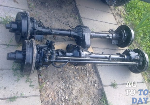
The old-style front axles, which include part of the UAZ-3741 design, do not differ much from similar new elements of the "Spicer" type. The fundamental differences between them lie only in the design of the crankcase, the dimensions of the constituent parts of the final drive and differential, as well as in some of the parts used.
The main part of the old axle is made up of a split crankcase, which consists of two divided halves, into each of which casings are pressed into with the axle shafts available inside. The covers are also provided for the presence of safety valves, which are responsible for limiting the increase in oil pressure in the system.
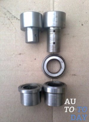
On the edges of the crankcase there are pivot assemblies, which include ball bearings with housings of the pivots (or pivots) on them. On the side opposite to the axle shaft, the trunnions themselves are attached to the trunnion housings, in which the wheel hub is mounted by means of two bearings. In the housings of the ball joints, there are hinges of equal angular velocities (CV joints), the outer trunnions of which are located in the hubs.
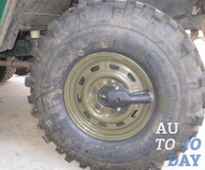
The main feature of the front axles of the UAZ is the presence in them of a mechanism for connecting the wheel hub with the semi-axle, which is made in the form of a clutch, with which it is possible to connect or disconnect the hub and the pivot of the hinge. This is what guarantees the transmission of torque from the differential to the wheel.
When the clutch is disengaged, the wheel hub can rotate freely on the trunnion, which means that the car will have a 4 × 2 wheel arrangement... In the event that the clutch is engaged, the wheel hub through the CV joint will be connected to the semi-axle and differential, and the car becomes all-wheel drive - 4 × 4. The front axles of the old representatives of UAZ, the design features of which are also characteristic of the "loaves", were equipped with hubs with drum brakes installed on them. To control the wheelbase on the bridge there are steering knuckle levers (located at the top of the steering knuckle housings) and steering rods connected to them.
As for the most common cause of various malfunctions of the front axle of the UAZ 3741, then, in most cases, the reason for their appearance is a violation of the axial clearance of the pivots. To check whether it is broken or not, it is enough to raise the front of the car with a jack and try to swing the wheel up and down. If axial play is observed, then it will be necessary to adjust the clearance of the pivots.
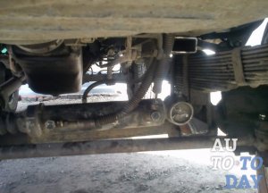
Considering that the UAZ-3741 has a frame structure, then dismantling the front axle will not be particularly difficult. To complete the task, you will need durable and high-quality jack, stops, which can withstand one and a half tons, and a special liquid WD-40, helping to unscrew rusted nuts.
- Place stops under the rear wheels and make sure that the vehicle is securely fixed.
- Disconnect the right and left brake pipes from the rubber hoses to the front brake drums.
- Unscrew the nuts securing the brake hoses and dismantle the hoses themselves.
- Unscrew the fastening nuts of the lower ends of the shock absorber and the bolts connecting the propeller shaft to the drive gear flange.
- Unscrew and unscrew the bipod ball pin nut and disconnect the tie rod from it.
- Now it is necessary to unscrew the fasteners (nuts) of the ladder of the front springs and remove the part (ladder) together with gaskets and linings.
- At the last stage of work, lift the front of the car by the frame and remove the bridge from under it.
At this point, the removal of the part can be considered complete, and if you decide to repair the front axle, you can proceed with the implementation of your plan.
Domestic off-road conditions cannot scare the owners of UAZ vehicles, but for their proper operation it is necessary to adhere to certain operating rules.
So, for example, UAZ ("loaf") has a front axle, the design of which imposes certain requirements on the control of the machine. Among other things, such axles provide for the disconnection of the wheel hubs and semi-axles, which contributes to an increase in the resource of the axle parts when the front drive is disconnected. Therefore, to turn on the front drive UAZ-3741, you will have to perform two steps: by turning the coupling, connect the wheel hub to the axle shaft, and then, using the lever, turn on the front drive.
As soon as the machine overcomes the problem section of the road, perform all actions in the reverse order: stop the vehicle, disengage the front axle using the lever and turn the clutch caps to the “4 × 2” position. After that, the car will be able to continue its movement as a normal rear-wheel drive vehicle.
Nevertheless, in the off-season and with constant use of the UAZ-3741 in off-road conditions, the clutches may not be disconnected, it is enough to adhere to a moderate speed mode.
Particularly noteworthy is the transmission oil poured into the axle, the replacement of which should be carried out in a timely manner (according to the manufacturer's recommendations - every 40,000 km of run or more often, depending on the specific operating conditions, the age of the vehicle and the quality of the lubricant filled in). It is also necessary to periodically change the oil in the CV joint, wheel hubs and steering knuckles, and in the drive axles of the "Spicer" type, the guide bushings of the disc brakes are additionally lubricated.
Regular maintenance and proper operation of the front and rear axles of the UAZ-3741 is a guarantee of reliable operation of the vehicle for many years.
| Video (click to play). |

