In detail: do-it-yourself gas 3110 front suspension repair from a real master for the site my.housecope.com.
Front suspension elements
1 - pivot of the steering knuckle;
2 - brake disc;
3 - rack;
4 - upper buffer;
5 - upper arm;
6 - shock absorber rod;
7 - cushions of the upper mounting of the shock absorber;
8 - the axis of the upper lever;
9 - spar;
10 - beam;
11 - rubber-metal hinges of the upper arm;
12 - lower arm;
13 - spring;
14 - lower spring cup;
15 - shock absorber;
16 - bottom buffer;
17 - kingpin;
18 - roller bearings of the wheel hub;
19 - grease nipples;
20, 21 - threaded hinges of the rack;
22 - rubber-metal hinges of the lower arm.
The king pins are the part of the front suspension that controls the handling of the vehicle. The wheels are attached to the beam through the pivots. Driving safety depends on their condition. During the operation of the car, the pivots require constant lubrication. In the event of large backlash in the suspension, it is required replacement of pivots with gas 3110.
- jack;
- wheel stops;
- a set of keys;
- screwdrivers;
- hammer and chisel;
- breakdown;
- a set of original pins with the number 3110-3001120.
The car must be put on the handbrake and turned on the first gear, then lift with a jack and remove the wheel.
Next, you need to remove the brake caliper from the steering knuckle. To do this, unscrew two bolts on the caliper: one from the bottom, the second from the top. After unscrewing the caliper, it must be removed from the brake disc, taken to the side and tied up so as not to damage the brake hose.
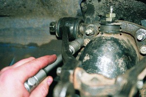
Disconnect the steering rod from the steering knuckle. To do this, unscrew the nut on the steering tip finger and squeeze the finger out of the steering knuckle eyelet.
| Video (click to play). |
Further, a stop is placed under the lower arm of the car, and the car is slightly lowered on the jack until the spring is compressed. Then the upper and lower bolts are twisted and knocked out, which secures the steering knuckle to the upper and lower levers.
The removed steering knuckle assembly is cleaned of dirt, then the grease fittings are turned out so as not to damage it during disassembly.
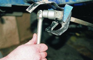
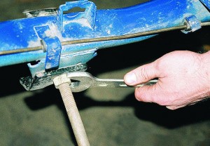
Using a sharp punch and a hammer, the corkscrew pin is knocked out through the hole in the steering knuckle.
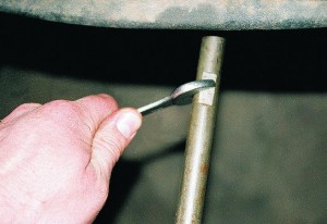
Leaning with a chisel on the side of the kingpin, and tapping it with a hammer alternately in both directions, the plugs of the kingpin are knocked out, after which the kingpin is knocked out.
Next, the rack is removed, the thrust bearing with rubber protection, as well as shims (they come in five sizes from 0.8–1.6 mm, in increments of 0.2 mm).
Through the holes with a screwdriver, the rubber o-rings of the needle bearings are removed.
With a hammer and a punch of the appropriate size, the needle bearings of the king pin are knocked out.
Installing a new king pin is carried out in the reverse order, provided that there are two holes in the needle bearing housing.
When installing the lower bearing, it is necessary to align two holes: one with the hole of the grease nipple, the other with the hole for lubricating the lower threaded joint. When installing the upper needle bearing, it is also necessary to line up the hole with the grease nipple. The thrust bearings are lubricated when assembling the unit.
During operation, the king pin is worn only on one side; to increase its service life, it can be turned. The pivot has a groove for a corkscrew pin. With an increase in wear of more than 0.3 mm, the pin can be knocked out, and the part can be rotated 90 degrees, while replacement of pivots on GAZ 3110 can be postponed to a later date.
The car is equipped with an independent pivot front suspension.
Beam 2 of the front suspension (cross member No. 2) is bolted to the body side members and is a supporting part for attaching the vehicle's power unit and suspension elements.
The upper 29 and lower 7 wishbones provide independent movement of each of the front wheels in the vertical plane (when overcoming road obstacles).
Rubber-metal bushings are pressed into the lugs of the inner ends of the upper and lower levers, by means of which the levers are connected to the axles and are fixed on the axles with nuts. The axes of the upper levers 29 are bolted to the beam, and the axes of the lower levers 7 are threaded pins 3 screwed into the threaded bushings of the front suspension beam.
From spontaneous unscrewing, the axles of the lower levers are fixed with locking brackets 1, which are bolted to the bushings of the beam. To the upper levers are bolted to the buffer 28 of the upper levers with supports. The cups of 9 front suspension springs are screwed to the lower arms. To the lugs of the outer ends of the levers with the help of pins 24 are fixed struts 22 of the front suspension with threaded joints pressed into the heads of the struts. The design of the upper and lower threaded joints of the rack is the same.
The car is equipped with an independent pivot front suspension. Front suspension beam 2 (cross member No. 2) is bolted to the body side members and is a supporting part for attaching the vehicle's power unit and suspension elements. The upper 29 and lower 7 wishbones provide independent movement of each of the front wheels in the vertical plane (when overcoming road obstacles).
The upper ends of the springs, through rubber gaskets 33, abut against the heads of the front suspension beam, and the lower ends against the spring cups 9 mounted on the lower arms. Shock absorbers 34 front suspension - telescopic, hydraulic, double-acting. The shock absorbers are installed inside the springs. The upper parts of the rods protruding from the shock absorbers are protected from dirt by rubber caps. The upper ends of the shock absorbers through rubber pads 38 and 39 are fixed in the heads of the front suspension beam, and the lower ends are attached to the spring cups. The anti-roll bar 6 is attached to the side members through two airbags 12 with clips 13 and to the front suspension spring cups through the struts 10. The stabilizer struts 10 are attached to the ends of the stabilizer bar and to the spring cups through rubber cushions 20 and 11.
GAZ 31 project Blueberry »› Logbook ›FULL FAQ on the front suspension gas 3110 replacing from pivot to ball
so I suffered for a long time and suffered with this suspension, I don't have any sensible information anywhere and I have to suck everything out of my finger here a bit there, and so on ... so I'll start my story half a year long ...
it all started in winter when he took blueberries, immediately thought about the Volvo bridge and the front ball. well, since the bridge needs to be made and the balls are almost a bolt, it was decided in the beginning I make balls and they have more sweets ...
and so the first question was, IS IT POSSIBLE TO PUT THE BALLS ON THE BEAM FROM THE PIVOT?
(I personally did not want to remove the beam from the car and hemorrhage with the motor, etc. ...)
answer-
CAN! everything fits perfectly, but you need to do a couple of improvements ...
in total, we take everything off the ball beam (i.e. 4 levers and knuckles)
all levers fit one in one EXCEPT one revision! you have to grind the silent block from the outside! that is, when the silent is hammered into its place in the center of its place, then we stupidly take the grinder and grind it flush with the lever and from the inside
he still remains native! and everything is screwed onto the bolts from the rolled thread, nothing rips off, and so on ...
the only difference, as people say, is that they have a different inclination of the cup from the springs ... honestly, by eye, I did not notice this and on the driving performance too.
The next thing that gnawed at me was the question of springs, since the Jeep Volga did not suit me and I got confused by this question very seriously ... but this is described in detail here A little about stiffness springs and understatement =)
THEN THERE WAS A QUESTION OF MIXING - I bought it and I have to bring it to the garage =) Volgovskaya suspension is very nice to fit into the trunk of our barge, I doubted very well, but nevertheless, at 02 Volga there the trunk is more likely to fit right in the assembly, in order to put it in 3110 you have to remove one steering knuckle (knock down 2 ball and that's it)
THE NEXT QUESTION - PUT THE BALLS WHERE THE VERSION?
ANSWER - autogas sculpted 3 types of trapezoids and 3 types of pendulums / bipods and 2 types of wheel bipods ...
hence we have the following set
1 view VOLGA WITHOUT GUR - long wheeled bipod, the shortest pendulum and steering bipod + curve (xs why but how many have not seen everywhere like this) trapezoid (photos will be further)
2 view VOLGA WITH GUROM - short wheeled bipod, middle pendulum and bipod gur and straight trapezoid
Type 3 VOLGA WITH GUROM N / O (tobish 105) - short wheeled bipod, the longest pendulum and bipod, a curved trapezoid because it can already rest against the motor =)
and now everything with a photo
Side view of the car GAZ 31105
The front suspension scheme is pivotless, located on the levers, with coiled springs, ball springs, shock absorbers and a stabilizer. At its base there is a beam made of hardened steel metal, on which all the main structural details are located. The strength of its connection with the frame gives the presence of a rod attached to the side members at one end, and the other - fastened to its center.
The design and arrangement of the front suspension on the car Volga 31105
The upper arm is made of carbon steel, secured with two bolts through the bushings. On the outer edge of this lever there is a platform in which there are special openings for fastening the ball (the connection is made using four bolts).
The structure of the lower arm is connected from two elements: front and rear, made of the same carbon steel. They are connected with a spring. The outer edges of both lever elements are held together by a single bolt. The inner edges are held using two bolts through the bushings and connected to the beam.
It looks like the front suspension of the Volga 31105
The swing arm is connected to the inner knuckle. From the outer edge, a trunnion is attached to it, on which there are lugs for connecting to the brake mechanism and the axle. The hub is driven by two bearings, in which the clearance is adjusted by rotating the hub nut.
The anti-roll bar consists of a bar and two struts. The bar is fixed in two places to the car body with metal pins softened with rubber pads.
Anti-roll bar Volga gaz 31105
The front suspension device is a complex design. If a knocking or extraneous noise appears, check and diagnose its condition to prevent unexpected breakdowns.
Causes and solutions to the problem:
- shock absorber breakage. The GAZ-31105 suspension uses a collapsible shock absorber, so you can change it or repair it;
- the development of rubber seals used in the connection of some elements, as a result of which a periodic knock will be heard in the trunk area. Replacement of worn-out rubber bands is required.
Useful advice! The price of these rubber elements is low. Therefore, it is recommended to buy the entire set of pillows and replace them completely.
- development of the hinge of the levers - replace them with new ones;
- the ball joint is worn out (the hinge of the stabilizer struts is broken). It is required to replace the struts together with the hinges;
- wear of the ball joints of the lever - replacement of the joints;
- large clearance in wheel bearings - clearance adjustment, bearing replacement;
- sagging, broken spring arch - replacement of the old spring with a new one.
The front suspension is independent, pivot, spring on double wishbones with telescopic shock absorbers.
The high rigidity of the suspension is provided by a forged steel beam on which parts of the suspension are installed. Stretching gives additional reliability to the fastening of the beam.At one end, it is screwed into the body of the beam, and at the other end, it is attached to the bracket of the cross member of the front side members.
The axle of the upper levers is attached to the upper part of the beam with two bolts. Between the axle and the beam there are 2 sets of shims for adjusting the angle of inclination of the kingpin and camber of the front wheels.
The 2 top steel forged arms are interconnected by the recoil buffer support. From one end, rubber-metal hinges are pressed into the holes of the levers, from the other, holes are made for the stand pin.
The lower arms are also steel, forged, fastened with a spring cup and also have pressed-in rubber-metal hinges and holes for the lower strut pin.
The pins screwed into the beam serve as the axis of the lower arm.
The front suspension strut is steel, forged, contains lugs for pressing in threaded hinges, as well as holes for installing a pivot in the upper and lower heads. In the lower part of the rack, there is a platform for fixing a rubber buffer limiting the upward travel of the suspension.
2 tapered roller bearings are pressed into the front wheel hub. They are protected from dust and dirt from the inside by a cuff, and from the outside by a threaded cap. The gap in the wheel bearings is adjusted with a lock nut.
The hub with bearings is located on the steering knuckle journal. When the wheel turns, the king pin rotates in the needle bearings of the rack.
The axial movement of the steering knuckle along the strut is limited by a stubborn ball bearing installed at the outer bearing of the strut.
Front suspension elements
1 stub axle;
18 roller bearings of the wheel hub;
20, 21 threaded pivot hinges;
22 rubber-metal lower arm joints.
Three grease fittings are screwed into the threaded holes of the front suspension struts. The upper one is predefined for lubricating the outer threaded joint, the middle one for lubricating the outer needle bearing of the king pin, and the lower one for injecting grease to the lower needle bearing and the lower threaded joint. Frequency of lubrication every 4 thousand km. We “inject” some of the friction with transmission oil until oil appears from under the seals on both sides of the bushings. The use of other, not recommended lubricants can lead to coking of the channels and, as a result, failure of hinges and bearings.
We control the clamping of the nuts of the outer and lower pins of the rack (12.020.0 kgf m), as well as the position of the o-rings of the threaded hinges and the protective cover of the thrust bearing.
Every 20 thousand km we control the clamping of the nuts of the axles of the upper levers (7.09.0 kgf m), the cross member to the bracket with a moment (2.73.6 kgf m). We tighten the nuts of the fingers of the threaded joints (12.020.0 kgf m). In addition, with a torque of 12.514.0 kgf m, we clamp the suspension fixing bolts to the car's side members.
We monitor the condition of the rubber bushings of the upper and lower suspension arms, anti-roll bar, rubber cushions, stabilizer struts, shock absorbers and rubber protective rings of the threaded joints of the strut.
Having jacked up the car, we mount the stop under the spring cup. We lower the car by compressing the spring until the rubber buffer of the upper arms moves away from the restriction. In this position, we control the presence of backlash in the hinges and suspension bearings.
We control and, if necessary, adjust the bearings of the front wheel hubs (see Correction of the hub bearings).
We also sometimes control and, if necessary, adjust the angles of the front wheels.
Removing the front suspension from the vehicle
PERFORMANCE ORDER
We jack up and hang the front of the car.
Disconnect the anti-roll bar from the side members
We support the crossbar (beam) with a jack.
We perform the same operations on the other side of the car, after which we smoothly lower the jack, monitoring the uniformity of the lowering of the suspension.
Install the suspension in reverse order.
1. Remove the steering knuckle with the strut.
2. Clean the unit from dust and dirt.
3. Clamp the post 4 in a vice and drive out the locking pin with a bit 1.
Knock out plugs 2 on both sides of the king pin.
To do this, place the key on the flats A of the king pin 3 and knock out the plugs with a hammer on the key in both directions.
4. Knock out the king pin 6 and disconnect the steering knuckle 1 from the strut 2, at the same time removing the ball bearing 5 with a protective cap. Remove the two rubber protecting rings 4 and press the needle bearings 3 out of the lugs of the strut.
5. Assemble in the reverse order of disassembly. When assembling, align the pin holes on the pivot and the steering knuckle lugs.
Needle bearings should be pressed in flush with the end of the groove under the plug using a brass mandrel with an outer diameter of 29.5 mm and a guide shank with a diameter of 20–0.50 and 20–0.10 mm (according to the inner diameter of the bearings).
When installing the bearings, the grease holes in the bearing housing and the strut head must match.
Before installing the pivot, it is necessary to lubricate the bearings with gear oil and select an adjusting washer so that there is a gap of no more than 0.2 mm between the lugs of the steering knuckle and the strut. The king pin plugs must be replaced with new ones. New plugs have a spherical shape, for their snug fit in the lugs of the rack, straighten them through a flat mandrel during installation.
It is recommended to install a new pin. Finger heads should be facing forward in the direction of the vehicle. It should be borne in mind that the final tightening of the threaded connections of the lever attachment is carried out only on the suspension, which is in a loaded state. The tightening torque of the pin nut is 120-200 Nm (12.0-20.0 kgcm).
6. Lubricate the bearings of the king pin with gear oil through grease fittings.
7. Adjust the wheel alignment angles. (Descent collapse of GAZ-3110)
Remove the front suspension strut assembly with a steering knuckle and a hub from the car.
1. Unscrew the grease fittings so as not to damage them during subsequent disassembly.
2. Hit hard with a hammer through a chisel or similar tool.
3.. knock out the locking pin.
4. We rest the chisel on the edges of the flat, and tapping on it with a hammer, we shift the pivot along its axis, first in one direction and then in the other direction.
5. . squeezing out the plugs to them.
6. With light blows of a hammer through the beard, knock out the kingpin
8. Remove the thrust bearing with a protective rubber ring
9. Remove the adjusting washer (washers can be of five sizes from 0.8 to 1.6 mm, pitch - 0.2 mm).
10. Use a screwdriver to pry on and remove the needle bearing sealing rubber rings from the holes.
11. Press out the needle bearings with a hammer through a mandrel of a suitable diameter.
12. Install the king pin in the reverse order, taking into account the fact that there are two holes in the needle bearing housing.
When installing the lower bearing, one of its holes should be aligned with the hole for the grease nipple, and the other with the channel for lubricating the lower threaded joint of the strut
At the upper needle bearing, we achieve alignment of one of the holes with the channel of the grease nipple.
The thrust bearing is lubricated during assembly.
During operation, the king pin wears out only on one side. To increase its service life, it has two flats for the locking pin.
If the side play of the king pin exceeds 0.3 mm, you can knock out the locking pin, turn the king pin 90 ° with a key until the second flat is aligned with the hole and reinstall the pin.
Removing the king pin or replacing the pin with a new one is not required.
one.Place the vehicle on a lift or a viewing ditch.
2. Remove dirt from the attachment points of the levers.
3. Loosen the wheel mounting bolts.
4. If the car is parked in a ditch, put the parking brake on the car, place the stops under the rear wheels, raise the front of the car and place it on the supports.
Remove the wheel. Place a jack (preferably hydraulic) under the spring cup and, lifting the cup with it, load the spring.
5. If the car is installed on a lift, first remove the wheel, and then put a stable support under the spring cup and, carefully lowering the car, load the spring.
7.
In this case, the possibility is not excluded that the spacer sleeve 3 will remain on the pin. In this case, the spacer sleeve must be removed from the pin by sawing or carefully cutting it off with a chisel. Clamp the lever 1 in a vice and press out the rubber bush 2 from it.
10. Thoroughly clean the lever eyelet from dirt and possibly remnants of the old bushing.
11. After wetting the new bushing with unleaded gasoline, insert the spacer bushing into it. Press the rubber grommet and spacer assembly into the lever lug using a drift.
12. Inspect the seat of the lever on the pin and, if necessary, clean the surface of the pin with a fine sandpaper.
13. Insert the pin into the bushing of the assembled arm.
We jack up the front of the car, place a stop under the spring cup and lower the car, compressing the spring. The upper buffer should move away from the stop.
One of the main advantages of the GAZ-31105 is the pivot-free suspension. The difference between this design is improved endurance. Noise and knocking while driving will now not so often annoy the driver and passengers of this car. In addition, now there is no need to do periodic injection of the system, and the repair and operation of the Volga 31105 have become noticeably easier and more convenient.
Side view of the car GAZ 31105
The front suspension scheme is pivotless, located on the levers, with coiled springs, ball springs, shock absorbers and a stabilizer. At its base there is a beam made of hardened steel metal, on which all the main structural details are located. The strength of its connection with the frame gives the presence of a rod attached to the side members at one end, and the other - fastened to its center.
The design and arrangement of the front suspension on the car Volga 31105
The upper arm is made of carbon steel, secured with two bolts through the bushings. On the outer edge of this lever there is a platform in which there are special openings for fastening the ball (the connection is made using four bolts).
The structure of the lower arm is connected from two elements: front and rear, made of the same carbon steel. They are connected with a spring. The outer edges of both lever elements are held together by a single bolt. The inner edges are held using two bolts through the bushings and connected to the beam.
It looks like the front suspension of the Volga 31105
The swing arm is connected to the inner knuckle. From the outer edge, a trunnion is attached to it, on which there are lugs for connecting to the brake mechanism and the axle. The hub is driven by two bearings, in which the clearance is adjusted by rotating the hub nut.
The anti-roll bar consists of a bar and two struts. The bar is fixed in two places to the car body with metal pins softened with rubber pads.
Anti-roll bar Volga gaz 31105
The front suspension device is a complex design.If a knocking or extraneous noise appears, check and diagnose its condition to prevent unexpected breakdowns.
Causes and solutions to the problem:
- shock absorber breakage. The GAZ-31105 suspension uses a collapsible shock absorber, so you can change it or repair it;
- the development of rubber seals used in the connection of some elements, as a result of which a periodic knock will be heard in the trunk area. Replacement of worn-out rubber bands is required.
Useful advice! The price of these rubber elements is low. Therefore, it is recommended to buy the entire set of pillows and replace them completely.
- development of the hinge of the levers - replace them with new ones;
- the ball joint is worn out (the hinge of the stabilizer struts is broken). It is required to replace the struts together with the hinges;
- wear of the ball joints of the lever - replacement of the joints;
- large clearance in wheel bearings - clearance adjustment, bearing replacement;
- sagging, broken spring arch - replacement of the old spring with a new one.
I had no problems! Everything except the sledgehammer was found and invented along the way, so I can't say anything specifically, unfortunately. I have already done this 4 times and every time I came up with a new idea! =)) Fortunately, there is no problem where I did it!
Added after 1 minute 1 second
I used a taper bushing (carved myself) soapy water and a vise! =)) Easy and fast!
Added after 1 minute 29 seconds
I used a belt and a mounting kit! =))
Added after 1 minute 21 seconds
I got paid 10 grand for this! =)) And 6 pieces for changing the bridge + old as a gift! =)) It was 15 years old! = R haha!
Added after 2 minutes 58 seconds
By the way, I also did this:
The lower honor of the king pin was put on the edge of the pit (the edge of the channel) and on 2 large nuts. I unscrewed the lower mount and lifted the car - the spring itself fell out. No danger of getting in the forehead! =))
If a monotonous metallic knock appears in the area of the front wheel, a suspension repair is necessary. In this case, you will need to change the threaded bushings, grease in the wheel bearings and the silent block on the lower arm. How this repair of the GAZ suspension looks like can be seen in the video from this section. The general approximate sequence of actions will look like this:
1. Jack up the car and remove the wheel.
2. Unscrew and press out the threaded bushing of the upper arm. We sit down a new bushing with heating.
3. Do the same with the lower arm.
4. Change the silent block.
5. We collect.
Now it will be clear to you how the gas 3110 front suspension repair looks like with your own hands. All the details in the video of this section.
Many elements of the front wheel suspension can be independently removed and reinstalled. For certain work, you still need tools from the workshop. In no case should the damaged parts of the suspension be straightened, let alone welded, they must be fundamentally replaced with new ones.
Removing the front suspension strut
Removing the shock absorber at the top. After removing the cover (1), you can loosen the suspension strut mounting nut using a spanner wrench (3). To do this, hold the shock absorber rod with an Allen key (2).
Removing the shock absorber at the bottom. Shown are the stabilizer link bolts (1) and the wheel bearing housing bolts (2 and 3).
When removing the shock absorber, you should take into account: if you disconnect it from the wheel bearing housing, you will have to re-adjust the wheel alignment angles, which is possible only on a measuring stand in the workshop.
For this reason, we describe here the removal of the shock absorber strut together with the wheel bearing housing.
Another addition: to tighten the upper nut of the shock absorber strut, mechanics in the workshop use a VW 3078 socket wrench.
- Purchase a new self-locking nut and a new swing arm clamping bolt.
- With the vehicle standing on the ground, loosen the central securing bolt of the drive shaft in the wheel hub (center of the wheel).
- Loosen the wheel bolts.
- Raise the vehicle evenly at the front to avoid stress on the stabilizer bar. Secure the vehicle.
- Remove the wheel.
- Disconnect the stabilizer link from both suspension struts, press the stabilizer up.
- Disconnect the disc brake caliper and secure it to the body with a wire - the brake line remains connected.
- Disengage the track rod joint.
- Remove the axle joint clamping bolt at the bottom of the suspension strut.
- Pull the pivot pin out of the strut using a pry bar. This separates the strut and the wishbone. In this case, under no circumstances should the slot in the wheel bearing housing be widened, for example with a screwdriver.
- Unscrew steering wheel and remove drive shaft from wheel hub.
- Remove the cover from the shock absorber cup in the engine compartment.
- Remove the nut of the suspension strut from the top of the rod. To do this, hold the stem with an Allen key.
- While doing this, hold the shock absorber strut underneath.
- Pull out suspension strut downwards and at the same time remove it completely from the drive shaft.
- For installation, use new self-locking nuts and a new clamping bolt of the suspension joint.
- Install the clamping bolt so that its head points forward in the direction of travel.
- Tightening torques: nut of the upper fastening of the shock absorber strut: 60 N • m, nut of the track rod: 30 N • m, clamping bolt of the independent suspension joint: 50 N • m, connecting rod of the stabilizer on the shock absorber strut: 40 N • m.
- If the same shock absorber strut is installed and the bolts connecting the wheel bearing housing and the shock strut remain clamped all the time, then there is no need to adjust the wheel alignment.
Elements of the front suspension strut and the sequence of their installation
1 - spring;
2 - spring plate;
3 - suspension strut bearing;
4 - buffer;
5 - protective casing;
6 - threaded cover:
7 - shock absorber;
8 - 10 - spacer, cover.
Audi 80 front wheel suspension at close range
1 - the body of the shock absorber;
2 - bolted connections of the shock absorber housing and the wheel bearing housing;
3 - wheel bearing housing;
4 - axial hinge;
5 - clamping bolt;
6 - the lower transverse suspension arm.
Left: Tie brackets are required to separate the spring from the shock absorber when the strut is removed.
Right: The illustration shows the suspension joint clamping bolt (1) with which the suspension joint (3) is attached to the wheel bearing housing. Further indicated: the fastening nuts (2) with which the suspension joint is connected to the lower wishbone.
Replacing the front shock absorber
To carry out this work (with the shock absorber removed), a device for tension (compression) of the spring is required. You will need at least two pullers, even better three. Without the use of a spring tensioner, the spline nut at the top of the shock absorber rod must not be loosened, because the spring is in a state of strong pre-tension. Otherwise, the components of the shock absorber strut will fly apart as in an explosion - there is a great risk of accidents!
In addition, the uncompressed spring can no longer be reinstalled. Spring tensioners are available at parts stores. Next, you need the following special tools: a VW 524 wrench to loosen the spline nut and a 40-201 A tool to loosen the screw cap above the shock absorber. If you don't have them, you will have to help yourself with a large pipe wrench.
- Remove the suspension strut (see previous section).
- Clamp the shock absorber strut through the wooden wedges at the height of the steering knuckle arm in a vice.Never pinch the cylindrical section, otherwise you will crush the shock strut.
- Install the spring tensioner at the spring coils and compress it slightly.
- To prevent the spring tensioner from slipping, cover these turns with adhesive tape, if necessary.
- Now loosen the spline nut at the top of the suspension strut. Hold the shock absorber rod with a wrench.
- Remove the spring together with the suspension strut bearing and additional parts.
- Remove the screw cap at the top of the shock absorber.
- Pull out the shock absorber.
- The factory is fitted with liquid shock absorbers. In this case, you need to pour out the old fluid from the shock absorber (special waste!) And clean its stem.
- Install a new shock absorber cartridge without fluid.
- The installation sequence of the constituent elements is shown in the figure on the upper right. Next, note that the color coding of the springs indicates the bottom.
- Tightening torques: threaded cover of the shock absorber cartridge: 150 N • m, slotted nut on the shock absorber rod: 50 N • m.
Removing the front wheel bearing
The wheel bearing with its outer ring is pressed into the housing, the wheel hub is pressed into the inner ring. Under no circumstances should a new wheel bearing be driven into its place with a hammer, otherwise you will "install" the next damage together with the bearing. Therefore, it is better to remove only the shock absorber itself and disconnect the brake disc, as well as the casing. And you must entrust the actual removal and installation of the bearing to the workshop, which has a repair press at its disposal.
- Purchase a new self-locking nut and a new swing arm clamping bolt.
- Raise the vehicle evenly at the front to avoid stress on the stabilizer bar. Secure the vehicle.
- Remove the suspension joint clamping bolt at the very bottom of the suspension strut.
- Use a pry bar to press out the independent suspension pivot pin at the shock absorber strut. In this case, under no circumstances should the slot in the wheel bearing housing be widened, for example with a screwdriver.
- Mark the installation position of the pivot on the lower wishbone.
- Unscrew the axle joint securing nuts at the bottom from the lower control arm. Remove the hinge.
- When screwing on the axle joint, take into account the marks made when removing the mark; in this case, the adjustment of the wheel alignment angles will remain approximately the same.
- Do not forget the shims for the fastening nuts.
- Tightening torques: the nuts of the independent suspension joint must be tightened to a torque of 65 N • m, the nuts of the clamping bolt to a torque of 50 N • m.
- Carry out wheel alignment in a workshop.
Removing the wishbone
- All self-locking nuts will need to be replaced as well as the bolts connecting the wishbone supports to the axle beam.
The wishbone can be removed with or without the axle joint. Which bolts need to be loosened in one case or another, is described in the previous section. - Remove nuts for inner bushings for wishbone support.
- If the inner bearings of the wishbone have already worn out, then before installing the lever it is better to immediately press in (in the workshop) new ones.
- Installation: Fasten the wishbone from the outside to the wheel bearing housing or to the independent suspension pivot. You will find the tightening torques in the previous section.
- Tighten the nuts for the inner bearings of the wishbone loosely at first. Tighten fully only when the vehicle is on its wheels. Otherwise, the wishbone bearings may become skewed.
- Tightening torques for the nuts of the inner bearings of the wishbone: first
40 N • m, then turn another 1/4 turn (90 °).
The arrow points to the lower mounting bolt under the rear strut on front wheel drive models.
| Video (click to play). |
Top suspension strut mount on the rear axle for front-wheel drive models.The arrows point to the four strut mounting bolts, the number (1) indicates the strut itself.

