In detail: do-it-yourself plunger pair repair from a real master for the site my.housecope.com.
Usage: restoration of worn surfaces of precision parts, such as plunger pairs of high-pressure fuel pumps. The essence of the invention: on a worn plunger, support surfaces are formed in the form of cylindrical belts, located evenly along the axis of the plunger, and closed strips along the perimeters of the cut-off grooves. The width of the strips and belts is chosen within 3-4 mm with their total area of 46-56% of the plunger area. The supporting surfaces are formed by electroerosive application of a two-layer coating with plastic deformation of the surface of the first layer of the coating, for example, wear-resistant from VK 8, before applying the second layer of antifriction material, for example, carried out with a copper-graphite electrode, after coating the plunger is rubbed in a cast iron lap with the addition of an abrasive pasta. The recovered pair is used instead of the new one. 1 ill.
The invention relates to a method for electroerosive restoration of worn surfaces of precision parts and can be used in mechanical engineering and repair of machines for restoration of plunger pairs of high-pressure fuel pumps (HPP).
There is a known method of restoring the working profile of parts operating under conditions of uneven wear, according to which a protective layer is preliminarily applied to the working surface of the profile of the parts, the thickness of which is the limiting one for the selected electroerosive mode (av.c. CCCP N 698746, class B 23 N 9/00 , 1979).
The disadvantage of this method is that the maximum layer thickness for the selected electroerosive mode is characterized by the concentration of defects and residual tensile stresses, which is undesirable when mating parts of precision pairs.
| Video (click to play). |
The closest to the proposed technical solution is a method for restoring plunger pairs, including the formation of a support surface on the plunger in the form of cylindrical belts with the application of an anti-friction coating (ed. N 1715864, C 21 D 1/78, 1992).
The known method does not provide a complete restoration of the service life and operational parameters of the plunger pair.
The basis of the invention is the task of implementing such a method that would increase the resource of the plunger pair, intensify in time the process of running-in of mating surfaces by improving the quality of restoration.
The problem is solved by the fact that in the method of restoring the plunger pair, including the formation of the support surface on the plunger in the form of cylindrical belts with the application of an anti-friction coating, according to the invention, the cylindrical belts are arranged evenly along the axis of the plunger and form additional support surfaces in the form of closed strips along the perimeters of the cut-off grooves , while the width of the strips and cylindrical belts is selected within 3-4 mm with their total area of 46-56% of the plunger surface area, the supporting surfaces are formed by electroerosive application of a two-layer coating with plastic deformation of the surface of the first coating layer before applying the second, antifrictional one.
The advantages of the applied method are that the application of the lower layer of the coating made of wear-resistant material, and the upper one of the anti-friction material provides not only high wear resistance, but also good grinding and running-in; surface plastic treatment of the lower layer before applying the upper layer ensures good adhesion of the layer to the substrate, a change in internal tensile stresses to internal compressive stresses and uniform distribution of the thickness of the coating layer.
The application of the coating in the form of evenly spaced stripes and along the perimeter of the cut-off groove ensures the formation of micro-indentations corresponding to the purpose of the labyrinth seals.
The values of the coverage area within 46-56% of the total recovery area with a coating stripe width of 3-4 mm are determined by additional experimental studies and provide a sufficient size of the supporting surface and the tightness of the plunger pair.
The drawing shows a General view of the assembled plunger pair, restored by the claimed method. The plunger pair includes: plunger 1, plunger sleeve 2, cut-off grooves 3, axial hole in plunger 4, diametrical hole in plunger 5, inlet hole in sleeve 6, bypass hole in sleeve 7, plunger working surface coating consisting of lower wear-resistant layer 8 and the upper antifriction layer 9.
An example of a specific implementation of the method.
A wear-resistant coating was applied to the worn-out high-pressure fuel pump plungers of KamAZ-740 diesel engines made of ShKh15 steel in places above the cut-off groove, below the cut-off groove, along the edges of the cut-off groove with a wear-resistant alloying electrode made of VK8 material under the following modes: current I 0.8A, current frequency f 200 Hz, doping time
After applying the coating, the restored surfaces of the plunger are treated with a special three-roller runner with a rolling force of 100 kgf. Re-coating of the same areas is performed with an antifriction alloying copper-graphite electrode at I 1.2A, f 200 Hz,


After increasing the outer diameter of the plunger in sections 8, 9, it is rubbed in a cast-iron lap with the addition of an abrasive paste, and then in conjunction with the plunger sleeve 2 with an abrasive paste. After that, the plunger pair restored in this way is used instead of a new one.
The study to determine the dependence of the operating time in hours of the restored plunger pair while ensuring the operational fuel supply on the width of the strip of the formed coating was carried out on a special STAR-12F stand for the cyclic fuel supply while ensuring the service life of at least 2500 hours. coatings from 3 mm or more, stable work is ensured. The limitation of the maximum width of the pavement strip of 4 mm is determined by economic feasibility.
The study to determine the dependence of the operating time in hours of the restored plunger pair while maintaining the coating strip width of 3-4 mm and ensuring the operational fuel supply depending on the ratio of the total area of the formed coating (Fcoating) to the plunger restoration area (Fplunger) was carried out on a special STAR stand -12F for a cyclic fuel supply while ensuring the service life of at least 3000 hours. of the formed coating strips of 3-4 mm with their uniform arrangement on the surface to be repaired and corresponding to the resource of the new plunger pair.
A method for restoring a plunger pair, in which the formation of a support surface on a plunger in the form of cylindrical bands includes the application of an anti-friction coating, characterized in that the cylindrical bands are arranged uniformly along the axis of the plunger and form additional support surfaces in the form of closed bands along the perimeters of the cut-off grooves, while the width of the bands and cylindrical belts are selected within 3-4 mm with their total area 46 to 56% of the plunger surface area, the support surfaces are formed by electroerosive application of a two-layer coating with plastic deformation of the surface of the first coating layer before applying the second, antifrictional one.
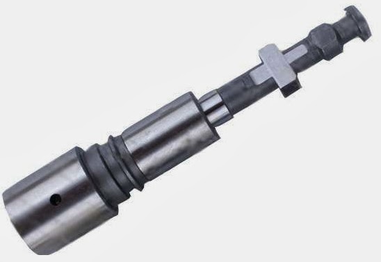
Let's start with the smallest, what is a plunger? A plunger is a kind of piston that is made in the form of a cylinder, its length exceeds its diameter. In diesel vehicles and fuel equipment, the so-called plunger pairs have become widespread. The plunger pair consists of a plunger and a sleeve.
The plunger pair is one of the main parts of the high pressure fuel pump or, for short, the injection pump. The high-pressure fuel pump marks and delivers the required portion of fuel at the right time to the engine. It also supplies it under a certain pressure and is supplied to the engine cylinders. In order to prevent fuel leakage at high pressure through the gap between the sleeve and the plunger, the gap is made very small, only 1-3 microns. Plunger and sleeve are made of high strength steel, hardened to high strength, resulting in a precise, high quality pair of parts that cannot be changed individually.
For plunger pairs, the presence of water in diesel fuel is destructive, since when it gets into the gap of precision parts, the fuel film that lubricates the pair on the rubbing surfaces is broken and the plunger runs without lubrication for some time. As a result, so-called “seizures” are formed on the surfaces, as a result of which they are jammed. Well, the water ingress itself is known from where, it is low quality diesel fuel, and water also contributes to the corrosion of the liner and plunger, this leads to an instant repair of the plungers.
In addition to water, also quite often problems arise as a result of microscopic dust particles entering the fuel, it works as an abrasive tool, and also harm the plunger pair in the pump. Due to the ingress of various impurities into the mechanism of the plunger pair, jamming and disruption of the pump and motor of the car also occurs, all this leads to repairs.
The plunger pair of the high-pressure pump is a high-precision mechanism and in order to avoid its failure, it is necessary to regularly diagnose the plunger pair and use high-quality fuel.
To diagnose the high-pressure pump plunger pair, it is necessary to have special equipment that allows you to check the degree of wear and the production of the plunger pair, and only then, if necessary, replace it with a new one or restore it. Repair of the plunger pair consists in the complete restoration of the geometric parameters of the sleeve and the plunger itself. The sleeve is refurbished by mechanical processing. The plunger is repaired by applying a wear-resistant hard chrome to it. Alone in a garage without equipment, i.e. in a handicraft way, it is impossible to repair the plungers.
Register to get an account. It's simple!
Already Registered? Sign in here.
Hello dear forum users!
Question / problem of this kind.
Hyundai Terracan 2.9 crdi, the coolant left, drove the car to the service, there are "specialists" (to tell the truth, the city is small and specialists in
We have almost no Hyundai) they said that the leak was due to the pump, the pump was replaced, we do not drive the car often, so only after a couple of months
noticed that the problem is not exhausted and the coolant still disappears and you have to top up. They drove off to another service, they said that the leak is coming from under the “front engine cover” and it is necessary to replace the gasket, which “squeezed out / worked out from time to time”. ), taking this into account and the fact that the service does not know whether it is necessary to remove the engine (they have not done such work yet), I have the following questions.
1. Do I need to remove the engine to replace this gasket, “under the front cover of the engine,” or can it be replaced without removing it?
If I understood the wizard correctly - who was explaining to me, it seems to “close” the windows of the cooling system, and be either under or around the pump. - (I bought a supported car, more recently, so it's weak in repairing them and other things)
2. Can one purchase and is sold separately?
Or do you buy a set and replace everything, or take a set and change only one? - they recommended buying the original kit, is it much better than the “non-original” one?
3.As I understand it, there is a high probability that the old pump is in order, and is quite functional, with a visual inspection I can somehow determine this, or just ask a specialist?
ps. Thank you in advance for your answers, if I created a topic somehow incorrectly, or in the wrong section, I apologize to the administration and, if possible, edit / move to the desired one.
ps2. On the Internet for a request for a cover, it appeared, is it she?
For the first time I am writing to the forum, I ask you to respond with a request to the new (not experienced) owner Terrik and forgive him for not knowing the technical part!
The problem began with the arrival of heat, I heard that a new sound appeared in the back of the car (at first I sinned on the rubber), it turned out not.
I came to the official service, the master lifted the car, said that for the replacement of the semi-axle bearings, which I successfully ordered with the help of the forum (they refused to replace me there, because they could not guarantee the quality of the repair, saying that they had already broken the semi-axle)
Signed up for a replacement in another office. When the service started, it turned out that these were not half-axle bearings, but the bearing of the driving gear of the rear axle (shank), they twisted the cardan with their hands and felt a bearing malfunction.
So I want to ask you, have you encountered this problem and are you right on the service?
If yes, tell me what is changing in parallel with the shank bearing (LSD bridge), what are the catalog numbers.
attached plunger marking and gasket repair kit for my 4JG2. Left spray. The masters said that it would suit me from Surf, Delica. In fact, it did not work out that way.
Do I need to lubricate the shaft itself with goya paste and pace it?
Plungers for this engine in store 5. I was advised to bring the old one and pick it up. The one that is for delica, surf, bighorn 9600, then on the rise 10800, 12000. My dearest 14500 rubles. From Japan, it was estimated by the plate (in another store) - 9600 rubles. But I got confused when the seller said that they are the same on all 4JG2s.
What is Goya pasta? Kill the plunger. Trust this business to artisans with a normal stand, I do not advise you to climb yourself. Surely there are no artisans in Yuzhno-Sakhalinsk. Plunger pairs are sold already lapped in the required size - the paste will only increase the gap, the pressure will drop and the steam will go to the trash heap. For example, at my brother's service, before assembly, the pump and steam are thoroughly washed, all the rubber bands and copper washers in the pump (yes, they are disposable), the oil seal are changed, then the assembled pump “runs” for a while at the stand, the pressure is measured, the starting “dose of fuel”, adjustment is in progress, etc. etc.
And the price tag is about 7-10 rubles for everything. Drove the car in the morning, picked it up in the afternoon - they will remove / install the pump, change the plunger, adjust it like a watch, if necessary - replace the timing belt, forehead oil seals, check the nozzles, replace the nozzles (all for an additional fee). The plunger pair is included in this money (recovered with chrome from a similar pump and whatever the opponents of this method say - I skated for 4 years myself and I don't even think to climb into the pump, I just changed the rubber bands a month ago, because the ring on the trigger was worn out and the pump began to leak - 30 minutes of operation).
PS: The main thing is to change the filter in time and do not fill in the solarium of unknown origin.
Technological process repair of plunger pairs by the method of chemical nickel plating includes the following operations:
- washing, control and sorting of parts;
- machining of plungers and sleeves;
- chemical nickel plating of plungers;
- processing of plungers after extension;
- selection and mutual grinding of parts;
- control and acceptance of pairs.
Flushing, control and sorting of plunger pairs... Control and sorting of plunger pairs consists in an external examination of parts and a tightness test. Particular attention should be paid to identifying corrosion. If traces of corrosion or longitudinal marks are found, the parts are repaired.Plunger assemblies having a smooth running surface are tested for tightness. Plunger couples, the density of which is less than the norm, are uncompleted; plungers and sleeves are sent for repair.
Plunger machining... In order to give the working surface the correct geometric shape, as well as to remove the strokes and risks, the parts are subjected to mechanical processing (preliminary and finishing). The preliminary lapping of the working surface of the plungers with a cast iron lapping is carried out on a special finishing headstock or a lathe.
Sleeve machining... Sleeve machining includes the following operations:
- preliminary lapping of the hole;
- fine lapping of the hole;
- lapping the end surface;
- control and sorting of parts into groups.
Chemical nickel plating of plungers... The surfaces of the plunger, which are not subject to chemical nickel plating, are covered with a thin and continuous layer of PVC varnish and dried in an oven at a temperature of 30-40 ° C. To ensure good adhesion of the alloy, the surface of the part is thoroughly degreased with gasoline and calcium-magnesium lime.
Post-build processing... If necessary, the parts are rubbed in to give the working surface a more regular geometric shape. The lap should move freely along the axis of the plunger at 150-200 rpm of the part. When processing, it is recommended to use a thin GOI paste. After thorough rinsing in gasoline, the parts are measured and sorted into groups according to the size of the diameters of the working surfaces with an interval of 2 microns.
Selection and mutual lapping... After the final machining, the plungers are selected and fitted to the sleeves. The plunger should fit into the sleeve for about the length of the running belt. Mutual grinding of parts is carried out at 150-200 rpm of the spindle. In this case, a thin paste of GOI or aluminum oxide is used. Move the sleeve along the plunger smoothly, without pressure. The end of the finishing is characterized by a more free movement of the sleeve over the entire guide surface.
Ready vapors are washed in gasoline and blown with compressed air.
Control and acceptance of pairs... The quality of lapping surfaces is determined by visual inspection and by checking the smooth movement of the plunger in the sleeve. The steam is then tested for density.
The lapped surfaces of the plunger and the sleeve should have an even shine, the presence of the smallest strokes barely visible to the eye is allowed.
After flushing the parts in diesel fuel, the plunger, extended from the sleeve by 40-50 mm, should, in a vertical position, under its own weight, lower to the stop against the end face of the sleeve. No local resistances, braking and sticking of the plunger in the sleeve are allowed.
The density of the plunger pairs is determined by pressure testing with a mixture of MT-16P oil and diesel fuel with a viscosity of 10 cc at 50 ° C.
Vapors are tested under a pressure of 300 kg / cm2 at a liquid temperature of 18-20 ° C.
On the rice. 164 a device for crimping plunger pairs is shown. The test pair is installed in a special removable sleeve 3, in which the sleeve is locked with a screw. The removable sleeve has grooves for installing the plunger along the angle of rotation relative to the liner windows in the position of maximum fuel supply. The bushing assembly with the tested pair is installed in the socket of the housing 9 of the device.
The end of the sleeve is sealed with a lapped heel 8 and clamped with a screw 6 through the rod 7. The weight 12 through the system of levers 1 and the pusher 2 moves the plunger up. Lever 5 is used to lift the load to the upper position, and latch 11 is used to secure it. A special lever 10 is designed to feed the plunger down when retesting.
Rice. 164. Device for crimping plunger pairs.
The pair is tested in the following order. The load is fixed in the upper position, the bushing of the device, together with the plunger bunk, is installed in the housing socket, the end of the sleeve is sealed and the cavity above the plunger is filled with pressing mixture, opening the valve 4 of the pipeline.Then the load latch is dropped. Under the action of the load, the plunger compresses the mixture to a pressure of 300 kg / cmg and, moving upward, gradually squeezes it out through the gap of the test pair. The duration of the fall of the load, by which the density of the pair is determined, is noted by the stopwatch. Each pair is crimped 3 times. The tests are considered correct if the difference between the obtained data of the two experiments does not exceed 3 seconds. If the difference is greater, the steam must be rinsed in clean diesel fuel and retested.
The reconditioned plunger assemblies are sorted according to their density into three groups. The first group includes pairs with a crimping time of 6-10 sec., The second - 10-15 sec. and by the third 15-20 juice. Each pump is equipped with plunger pairs of the same density group.
Vapors that do not meet the technical conditions in terms of density are sent for re-equipment. In the event of slight seizure, the plunger pair is again thoroughly washed in clean diesel fuel and pressurized again.
For a systematic check of the state of the stand, control and reference pairs are used. In addition, a control sleeve is produced for each stand. Using this bushing, two plunger pairs are selected from the number of new parts, the density of which corresponds to the crimping time 6; 10 and 20 sec. The selection of plunger balls is carried out at a temperature of 18 ° C using a standard mixture. Control pairs are marked: "K-6 sec"; К-10 sec "and" К-20 sec ". These vapors are stored at the OTK plant.
For reference parts, the following marking is adopted: "E-6 sec"; "E-10 sec" and "E-20 sec". These pairs are used by the workshop supervisor.
The permissible difference in density between the reference and control pairs is 0.5 sec. for couples with a density of 6 and 10 sec. and 1 sec. for couples with a density of 20 sec.
Every day at the beginning of work, as well as after filling the stand tank with a fresh mixture, the density of the reference pairs on the stand working sleeve is measured.
The readings of the stand are considered correct if the obtained vapor density differs from the nominal (marked on the reference pair) by no more than 1 sec. for couples with a density of 6 sec., for 2 sec. for couples with a density of 10 sec. and pa 4 sec. for couples with a density of 20 sec. If the difference in readings is greater than the indicated values, then the reference pair is checked against the control sleeve. The permissible difference in readings when testing the reference pair on the control and working bushings is allowed no more than 0.5 sec. for couples with a density of 6 and 10 sec. n 1 sec. for couples with a density of 20 sec. If the difference in the test results is greater, then the working bush of the stand and the sealing heel are replaced with new parts. The reference pair is checked twice a month against the reference pair on the reference sleeve.
After sorting into groups, the plunger pairs are branded. Parts intended for long-term storage are canned. For this, the plunger pair is washed in pure gasoline, dried, fixed in a special frame and immersed in a bath with aviation oil at a temperature of 110-120 ° C. After the cessation of the allocation of foam, the frame with the details is removed. After the oil drains from the surface of the parts, the frame for 2-3 sec. immersed in a bath with a preservative mixture containing 100 g of paraffin per 1 kg of aviation oil. The temperature of the mixture is 75-85 ° С.
After conservation, each pair is wrapped in parchment-waxed or azocerite paper and placed in a box.
Attention! Car service network of favorable prices. Camber check is FREE! No queues! Repair on the same day!
Download / Print topic
Download a theme in various formats, or view a printable version of the theme.
The high pressure fuel pump is an essential component in every diesel engine. Because of this mechanism, the fuel becomes not just a liquid, but a fuel-air mixture. A part such as a plunger pair also acts on the operation of the pump. She is responsible for fuel supply and distribution.
There are two main parts in the design of this element - the plunger and the sleeve.
The plunger consists of a small cylindrical piston. When the pump is running, the plunger moves inside the sleeve. Performing up and down movements, the plunger sucks in fuel, and then it is pumped alternately into the nozzles of the working cylinders, where it ignites under high pressure in an atomized state. The plunger pair of the high pressure fuel pump has several holes on the sleeve through which diesel fuel is supplied for subsequent injection.
In other words, the main purpose of the plunger pair is to accurately measure the fuel, so that it can then be fed into the engine cylinders. Also, this element helps the pump to supply fuel at the right moment with the right pressure. In order for everything to be carried out without interruptions, it is necessary that the plunger pair meet all the requirements. Therefore, the plunger pair, the price of which is not so small, must be produced on high-tech equipment, it is unrealistic to make it at home.
Plunger pair of injection pump - a complex element, it must be operated with caution and the necessary requirements must be constantly observed. In order for the device to work smoothly and efficiently, only high quality fuel should be used. Since the fuel quality at our filling stations leaves much to be desired, the restoration of plunger pairs is a very popular service.
Low-quality fuel contains a large amount of chemical elements, which significantly reduces the durability of the plunger pair. The most negative effect is produced by water, which enters the fuel as condensate. If there is a lot of water between the sleeve and the plunger, then the lubricating film breaks its integrity and then the part works without lubrication. This can deform the part so much that restoring the plunger pairs simply will not help. All that remains is to buy a plunger pair in the store and try to refuel only with high-quality fuel.
There are several signs that a part is defective. One of them is the refusal of the motor to start, especially when the motor is warmed up. It is possible to find out whether the plunger pair of the injection pump is working normally while the engine is running. We must pay attention to the quality of his work. If the plunger pair is faulty, then the motor loses power, and it works with uncharacteristic sounds. In addition, the engine may run intermittently and become unstable. If at least one symptom was noticed, then it is necessary to make a diagnosis.
It should be noted that special equipment is used for diagnostics. Therefore, it is very difficult to say at home whether the plunger pair is faulty or not. In the service station, professionals can say for sure about the malfunction and the method of solving this is adjustment or complete replacement. During the repair, special equipment is needed to restore the tightness of the sleeve and plunger.
Now it should be told how to replace the plunger pair. First you need to go to the store, pick up and buy a plunger pair that will fit a particular engine. It is necessary to disassemble everything that is removed around the fuel pump. This is necessary in order to remove the old plunger pair without problems and nothing gets in the way. Then you need to remove the front cover of the engine, unscrew the nut securing the drive gear, and then unscrew all the tubes and remove the fuel pump. All parts that are in the dirt must be cleaned at the same time. Only then can you begin to disassemble the fuel pump, unscrew the plunger pair itself, but only do it with extreme caution and in a specially prepared place with a set of necessary tools.
It is necessary to carefully drain the fuel from it, dismantle the old plunger pair, check the condition of the remaining parts, namely the cam washer, rollers, the booster pump, etc.Then you can reassemble everything in the reverse order, after thoroughly washing the plunger pair with diesel fuel from preservation before installation.
To adjust the amount of fuel that is injected, there is a special cut-off lip on the plunger. When the movement of the plunger goes up, it first closes the outlet hole, and through this edge the hole opens slightly. The cutting of this edge is made with a spiral, so that when the plunger is turned, the time before the cut-off changes. In order for the plunger to rotate and make translational movements, it rests on the cam washer and engages with its pin. When the washer rotates, it also rotates the plunger, and the cams run into the rollers and push it. The plunger is adjusted with shims of different thickness. The most important thing is not to forget that the price of a plunger pair is quite high, it is a very fragile and complex part, so it must be handled very carefully.
The operation of a diesel engine is four strokes, during which a combustible mixture of fuel and air is formed. Ignition occurs not due to a spark, but due to high pressure, therefore, the compression ratio of diesel engines is always increased.
Cummins Inc. Is one of the world's leading manufacturers of diesel engines and generators. The engines of this company are very different: power varies from 30 to 3600 horsepower, and engine sizes from 1.5 to 90 liters.
There is no more complex and critical unit in a diesel engine than the fuel injection system, more precisely, its main part - the high-pressure fuel pump. Many mating parts, high-loaded units, the presence of a precision dosing system, make the repair of the injection pump a difficult task even in service conditions. It is all the more difficult to repair the high pressure fuel pump of a diesel engine with your own hands.
In automotive technology, almost everything is repaired, except, perhaps, individual oil seals and cuffs, the repair of which is impossible without special materials. The complexity of setting, diagnosing and repairing the injection pump requires the employee to have skills in working with precision mechanics.
It is simply impossible to adjust according to the factory parameters, without a special diagnostic stand for the repair of the injection pump. In the course of a diagnostic study of the injection pump, it is necessary to check:
- cyclic supply of the high-pressure pump, in the entire range of revolutions of the injection pump shaft, at start-up, and after cutting off the fuel supply;
- stability of the developed pressure;
- uniformity of the injection pump delivery to the fuel injector.
Even having access to a diagnostic stand, and having studied the issue of repairing a high-pressure fuel pump using numerous videos, it is very difficult to qualitatively check and evaluate its work.
In heavy diesel engines, plunger, in-line injection pumps are used. In maintenance and repair, such devices are more difficult, since they require special equipment for its disassembly, therefore we will not consider such high pressure fuel pumps and their repair.
In a passenger diesel engine, a distribution type injection pump is almost always used. Unlike in-line pumps, in a distribution pump, the force is transmitted to the plunger using a profiled cam washer. The design of the injection pump turned out to be more compact, but it is hardly simpler to expect to carry out its repair on the knee.
The most famous and affordable is the Bosh VP44 injection pump. Often, the need to repair the pump internals arises when:
- poor traction and incomplete combustion of fuel even under ideal conditions - in the absence of load and a thoroughly warmed up engine;
- a sudden failure and stoppage of a diesel engine under load, which is called “death on takeoff”. Usually the scanner in such cases diagnoses the code P1630 and P1651.
- the appearance of a diesel fuel leak in the area of the gland seal of the central shaft of the injection pump.
Therefore, we will restrict ourselves to the issue of repairing the injection pump with our own hands by replacing the seals and eliminating the scoring of the working surfaces of the parts.
Before disassembling the pump drive shaft seal, try to move it radially. If play is felt with your hands, it is possible that the reason for the leakage of fuel is the wear of the working surface of the shaft or requires repair of the bearing.
A large number of split planes and mating surfaces of parts required the use of a large number of seals and glands. As a rule, they are made of quality material and last long enough until they are damaged during repair or maintenance. In this case, standard repair kits are used for DIY repair of Bosch injection pumps.
It is quite easy to replace the seal on the shaft position sensor and on the automatic injection timing during repairs. For a better fit, you can drip a few drops of spindle or engine oil onto new rings and rubber bands.
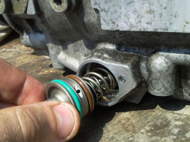
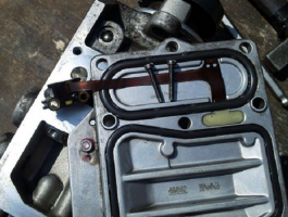

For preventive repair of a Bosch injection pump with your own hands, you will need to disassemble the pump in approximately the following order:
- remove the metering valve from the end of the injection pump. To do this, unscrew the four screws of the pressure plate, carefully release the cable of the injection advance valve. By removing the three screws securing the metering valve, you can carefully remove it from the seat;
- by unscrewing the fastener on the top cover, you can remove the control board and gain access to the electronics;
- we set the position of the shaft, as shown in the photo, remove the camera and get access to the insides of the injection pump;
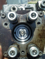
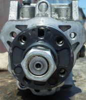

- after dismantling the bearing using a special puller, we get the opportunity to study the potential culprit for the poor performance of the injection pump - the piston of the injection advance unit. There is often surface wear and edge scuffing on the part. You can try to make repairs by polishing the surface, replacing the whole part is much more expensive.
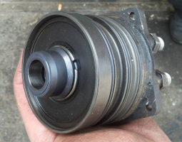
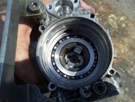

After the repair, the assembly is carried out in the reverse order with the washing of the parts with diesel fuel.
Often, in addition to scoring, on the surface of the pistons, there is another reason why the injection pump does not develop the required pressure. This could be due to debris, films, or wax build-up on the filter screen inside the pump. There is a mesh on the side of the inlet pipe. Rinsing the channels is a troublesome and ineffective business, it is easier to remove the mesh and blow it with compressed air.
Torn pieces of debris can jam the plunger piston or even break or break the pump drive shaft. Therefore, cleaning should be done very carefully to avoid contamination of the internal cavities of the pump.
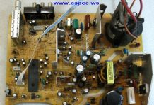
Among the many reasons for the failure of the electronic "liver" of the injection pump, the most common is the breakage or burnout of the contacts of the control board and the failure of the power transistors. If the knowledge and skills of working with electronic devices allow to carry out a "continuity" of the transistor performance and repair, it is worth trying to identify the cause and replace the culprit with a serviceable element.
To check the condition of the "culprit", you need to carefully open the black cover, which is tightly seated on the rubber seal with screws. It should be removed carefully so as not to damage the seal itself.
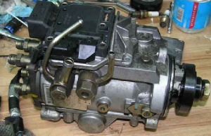
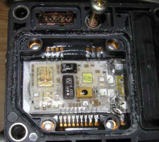

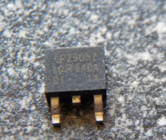

The reason for the failure of not only the transistor, but also the entire board could be air trapped in the cavity due to poor operation of the drainage system or the check valve. Often, they try to eliminate the airing by spinning up with a starter, hoping to pump diesel fuel into the high-pressure fuel pump in this way. At this moment, the transistor is open and loaded as much as possible, which leads to intense heating. In an air environment with poor heat dissipation, it will inevitably burn out. In some German cars there is a protection that prevents an attempt to start the engine in the absence of fuel in the highway. For this, a fuel sensor in the tank is used.
Failure of the transistor can be established by "dialing" a tester or by its appearance. The best option for repairing such a malfunction would be to replace the entire control board.Perhaps it is more expensive than soldering, but it will give guaranteed quality and stable operation of the injection pump after repair. As a last resort, give the board and the transistor for soldering to electronics specialists.
When installing and reassembling after repairs, check the tightness of all fasteners.
If during the audit you did not make rash and unreasonable replacements of parts, the assembled pump should work with approximately the same parameters as before. Bosch EPS-815 stand is used as a standard for testing and adjusting injection pump after overhaul.
The video shows how to raise the plunger pressure in a Bosch VE injection pump:
| Video (click to play). |


