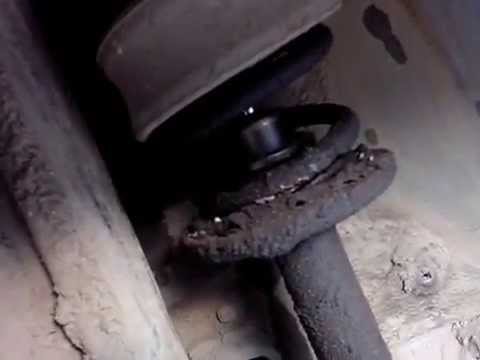
In detail: do-it-yourself repair of the Audi A4 B5 suspension from a real master for the site my.housecope.com.
A moment comes when the silent blocks on the car become unusable and require replacement. Today I will show you how to replace the silent block of the lower rear wishbone of the front suspension with an Audi A4 / Passat B5 myself. Of course, you do not have to bother with replacing the silentblock, but simply buy the entire lower rear wishbone, that is, with a pressed-in silentblock. But why pay extra for the lever if it is in excellent condition with a ball joint. And yet, if you do not know how to remove the lever, you can see here: Change the Lower Arm of the Front Suspension on Audi A4 / Passat B5
And so, to replace the silent block, you need a press. Of course, you can try to press out and press in the silent block in a vice. But usually the silent block `` sits '' very tightly in the lever and there is a chance that your vise will break. You can try to work with a sledgehammer, but it is possible that the lever will burst. Therefore, the best option is the press.
You will also need a mandrel for the silent block, and of course know how to press it in correctly. For all the nuances of replacing the silent block of the lower rear arm of the front suspension, see the video:
1 - Support
2 - the Amortization rack
3 - Console
4 - Beam of the power unit
5 - the Anti-roll bar
6 - the Drive shaft
7 - "Tripode" hinge
8 - the Back lever
Front wheel suspension elements
1 - Bolt, 75Nm
2 - Washer
3 - Bolt. Be sure to replace
4 - Upper rear suspension arm. Replace the support
5 - Bolt, 7Nm
6 - the Bolt
7 - Self-locking nut, 50Nm, be sure to replace
8 - the Bolt
9 - Self-locking nut, 40Nm, be sure to replace
10 - Upper front suspension arm. Can only be removed together with the support
11 - the Amortization rack
12 - Bolt. Be sure to replace
13 - Guide arm with hydraulic support. If significant oil leaks appear on the hydraulic support, the support must be replaced.
14 - Nut, 120Nm, self-locking. Be sure to replace
15 - Wheel bearing housing
16 - Collar bolt, be sure to replace. Torque:
bolt М14: 115Nm and then turn 180 °;
bolt М16: 190Nm and then turn 180 °;
17 - Bolt, 10Nm
18 - the Cover
19 - Nut, 90Nm, self-locking. Be sure to replace
20 - Bolt
| Video (click to play). |
The four-link, independent front wheel suspension has McPherson struts and a torsion bar anti-roll bar.
The shock struts are composed of coil springs, double tube shock absorbers and oversized upper legs. The stabilizer does not participate in the direction of the wheels, but is connected to the shock absorber struts through the connecting rods.
The strut is bolted to the upper arm support and to the front wishbone.
Optimum handling and minimum tire wear are only achieved when the wheels are in the correct position. In case of improper tire wear, as well as in case of insufficient stability on the road, it is necessary to make optical measurements and, if necessary, adjust the wheel alignment angles.
The transmission of torque of the power unit to the wheels is carried out through two drive shafts, each of which, through two hinges of equal angular speeds, is connected to the wheels and the final drive.
There are many legends and stories about the innovative aluminum multi-link front suspension of the Volkswagen corporation, which first appeared on the Audi A4 and subsequently installed on the Audi A6, A8, Allroad, Volkswagen Passat and Skoda Superb.
- The B5 has such a sore - its aluminum suspension on our roads usually requires repairs already for 40-60 thousand mileage, while not a single part is changed, but the entire non-separable suspension assembly assembled, so repairs are very expensive.
- At first glance, the suspension of the Volkswagen Passat b5 does not represent something special. The MacPherson struts in the front and the curling “P” -shaped beam in the rear have long been familiar to owners of the compact class.
- Regarding the trade winds, the car is not bad, but the suspension is rather weak and harsh.
Well, let's figure out where the truth is and where the fiction is in this very discussed suspension design.
The last few decades of development in the design of the front suspension have led to the fact that mainly two types have been used - two linkage (on each side), which provide greater comfort and control, and one linkage with a McPherson shock absorber strut (McPherson), which became the main compact cars due to the low cost and small size of the upper part due to the lack of an upper arm.
When designing a new car platform, Volkswagen was guided by the highest levels of comfort and handling, so it did not just choose a two-link system, but improved it by dividing each lever into two more levers in order to achieve the most ideal positioning of the steered wheel in all driving modes.
The two upper levers are connected from the outside with ball bearings to the steering knuckle, and the inner end through the silent blocks are attached to a rigid bracket, to which a shock absorber is attached through a rubber damper. The bottom of the shock is bolted directly to the lower front arm. The lower levers are also connected with the outer part through ball bearings to the steering knuckle, and with the inner silent blocks to the subframe. Thus, the highest rigidity of the suspension structure is ensured, which makes it possible to exclude violation of the design position of the wheel even at maximum loads. To reduce the inertia of the sprung masses, the levers are made of aluminum alloy; after modernization, they began to make the steering knuckle from it.
The main load when driving is taken by the lower arms, since they are attached to the swing arm only slightly below the wheel centerline, and the upper ones are much higher than the axis. The front lower arms mainly take up lateral loads, and all the impacts from bumps in the road go to the rear.
The use of the longitudinal arrangement of the motor and, accordingly, the gearbox made it possible to almost perfectly align the flanges of the gearbox drives with the wheel center and get rid of parasitic torques in the mode of a sharp acceleration.
Suspension arms Audi A4 / A6 / Passat B5:
The list of spare parts on the diagram of the support arm, hub bearing housing and vehicle stabilizer:
The replacement has been made. It turned out to be simpler than a steamed turnip. No removal of the beam, unscrewing brake pipes, etc.
Of the specific. You need to have an 18 wrench to unscrew the silencer bolts - a ring, plus a head of the same size. I used a 18 head and a cap for 19. I survived - the edges did not lick off. It can be made from a spanner wrench 17 with a grinder to 18, if you wish. 🙂
We unscrew only the central bolt of the silent block. Nothing more! We take out the bolt, holding the beam. We repeat on the second side. The beam will lower a little. The brake hoses will not break, nothing will happen, there is no need to be afraid. We take a screwdriver and drive it with a hammer between the beam and the silent, periodically removing it after the blows and see that it (the screwdriver) goes more or less evenly along the silencer. After 2 minutes of beating, the silent strips came off from 2 sides without any problems.
Next, we put a washer under a long bolt, grease the silent with graphite, insert the silent a little into the beam, insert the bolt into the silent, from the inside of the machine on the bolt we put on a piece of pipe, a washer, tighten the nut and start squeezing everything by tightening the nut with a ratchet.Silent will slowly but surely fall into place. After installing the silencers on both sides, we raise the beam, having previously lubricated the native bolts of the silencers with graphite. We insert the bolts into the silent, catch the ear of the body. We bait the nuts. The bolt may not go into the ear of the body attachment, but the second person should push the wheels from the outside, wiggle them to line up the hole.
After tightening the nuts hands not up to the end we swing the car from the outside (from the ground) from side to side so that the beam and the bushings settle down and there are no distortions.
Everything. The work was carried out in a garage pit. Better together.
Pysy: to put the silentlets with slots parallel to the ground - that's for sure, I had my own originals like that, i.e. in my picture the red line is parallel to the ground.
The described A4 body is a sedan.
–Careless Angel 13:17, 22 September 2009 (EEST)
Replacing the lower arm of the front suspension. Audi A4 / Passat B5. Greetings. In today's video, I will show, using the Audi A4 as an example (this also applies to the Passat B5), how to remove (replace) the lower arm of the front suspension. People call it "boomerang" for its curvature similar to a boomerang.
I have a question for the owners of Audi and Folz, I want to purchase levers from the supplier JP grup, has anyone used this company?
Tell me, do you pull the upper levers only when the machine is lowered? Thank you!
tell me about the rear suspension
not all of my lever came off with an insert, the one in the pivot pin and tightly on the ball seat is not possible to knock down
Dismantling the front wheel suspension
Details of the front suspension strut and the sequence of their assembly
1 - nut with a flange;
2 - suspension strut bearing;
3 - intermediate washer;
4 - upper spring plate;
5 - spring;
6 - shock absorber buffer;
7 - protective shell;
8 - protective cap;
9 - bottom lining for the spring;
10 - lower spring plate;
11 - shock absorber.
Left: Dismantling the suspension strut at the top. After removing both protective caps, you can loosen the nuts "1" and "2" of the upper rigid mounting of the shock absorber strut.
Right: Dismantling the suspension strut at the bottom. The arrow points to the screw connection to the front wishbone at the bottom.
Front shock absorber dismantled
1 - the upper bearing of the shock absorber;
2 - spring;
3 - shock absorber;
4 - fork head.
In order to separate the spring from the shock absorber in the dismantled strut, use spring-loaded clamps (arrows).
Left: the position of the corner (A) of the upper spring plate on the right (R) and left (L) is mirrored in relation to the screwing axis at the bottom of the fork head (1). The arrow shows the direction of travel (F).
Right: Mounting position of the lower spring plate (1) on the shock absorber (2): the hole (arrow) is 90 ° outward offset in relation to the screw shaft (A).
Much can be disassembled and reassembled in the front wheel suspension assemblies, although for certain work you need tools from the workshop. Damaged wheel suspension parts cannot be straightened or even welded; they only need to be replaced.
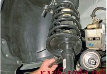
Removing the front suspension strut
Removing the shock absorber strut in the Audi A4 is not particularly labor-intensive. The nice thing is that you don't have to re-measure the wheel alignment.
- Purchase new self-locking nuts for securing the shock strut at the bottom and top and for the upper screw connection of the bearing pivot.
- Lift up both rubber ends in the dampening tank (they cover the upper screw connections on the shock strut).
- Unscrew both nuts of the shock absorber under them.
- Raise and secure the front of the vehicle.
- Remove the wheel.
- Disconnect the cable to the ABS speed sensor on the shock absorber strut.
- Unscrew the upper axle joint clamping bolt nut. Remove the clamping bolt.
- Remove the axle pivots upward from the wheel bearing housing (knuckles).In doing so, do not, for example, widen the slot in the wheel bearing housing with a screwdriver.
- Do not wring out the track rod joint.
- Fold out the wheel bearing housing.
- Unscrew the bottom screw connection of the shock absorber strut.
- Carefully remove the strut from the wheel housing.
- Installation: Install the shock absorber strut so that the hole in the lower spring plate is towards the center of the vehicle.
- Tighten the lower suspension strut mount to 90 Nm.
- Insert the bearing pivots into the wheel bearing housing as far as they will go.
- Insert the clamping bolt of the upper axle pivots, tighten the nut to 40 Nm.
- Reattach the ABS wire.
- Tighten the upper suspension strut nuts to 20 Nm.
Replacing the front shock absorber
For this work, which is carried out on the dismantled strut, a spring tensioner is required. At least two tensioners are used; better than three. Without using a tensioner, the flanged nut at the top of the piston of the shock absorber piston must not be loosened, as the spring is under high pre-tension. Suspension strut parts can fly in different directions, as in an explosion - extreme risk of injury! In addition, a weakened spring cannot be installed.
- Remove the shock absorber strut.
- Clamp the suspension strut at the fork head in a vice. Never tighten in the area of the cylindrical part, otherwise the shock strut will be compressed.
- Place the tensioner over the spring coils and compress the spring slightly.
- To prevent the tensioners from slipping, cover the corresponding coils of the spring with adhesive tape.
- Loosen the flanged nut at the top of the strut. Using an Allen key, press the shock absorber piston rod in the opposite direction.
- Remove the spring with accessories.
- Remove the protective cap and pad under the spring.
- Separate the spring plate with a plastic hammer and remove it.
- Installation: slide the spring plate onto the new shock absorber.
- Pay attention to the installation position: the hole in the spring plate must be offset by 90 ° in relation to the holes in the yoke at the bottom of the shock absorber (tolerance is only 2 °).
- Install the spring pad, protective cap and sheath, and a thrust damper.
- Place the spring on the plate, which is still under tension; make sure that the lower end of the spring coils is in contact with the spring plate stop.
- Slide on the upper spring plate with the suspension strut bearing and washer.
- Screw the spring plate 11 ° in accordance with the figure to the screwing axis of the shock absorber (at the bottom of the fork head). There are different directions on the right and left side.
- Work precisely: the tolerance is only 2 °.
- Tighten the flanged nut at the top of the shock strut to 60 Nm. Using an Allen key, press the shock absorber piston rod in the opposite direction.
- Loosen the spring tension, while making sure that the end of the spring is in contact with the spring pad stop.
Removing the front wheel bearing
Here, numbers (1-3) represent the front axle upper bearing bracket retaining bolts.
The wheel bearing with its outer ring is pressed into the housing, the wheel hub is pressed into the inner ring of the bearing. The new wheel bearing must never be hammered into the seat with a hammer, otherwise the nearest damage will be “mounted with it”. Therefore, the bearing is squeezed out and pressed in by a workshop, where a repair press is available.
Replacing the independent axle suspension arm
Both arrows point to the so-called flange nuts, with which the axle pivots are attached to the wheel bearing housing.
The bearing pivots (axle pivots) on the four suspension arms on each outer side of the front axle cannot be purchased separately, as can their cuffs.It follows from this that in case of a defect in the bearing hinge, it is necessary to immediately change the entire independent suspension arm.
This is not the case with the rubber mounts on the inside of the axle suspension arms. They can be wrung out and pressed in the workshop separately. In this case, it is necessary to precisely adhere to their installation position. We prefer and describe the complete replacement as the press-fit must be done in the workshop. In addition, in this case, the axle joint is replaced at the same time, thereby eliminating the next defect in the same unit.
Removal of both control arms of the axle suspension at the top
- All self-locking nuts and bolts of the axle / bracket arm bearing should be replaced; buy new ones.
- First remove the bracket at the top: the car must be lifted and secured.
- Unscrew the three bracket mounting bolts in the engine compartment.
- Dismantle the wheel.
- Disconnect the ABS speed sensor wire on the shock absorber strut.
- Unscrew the nut of the clamping bolt of the upper axle pivots. Unscrew the clamping bolt.
- Remove the axle pivots at the top from the wheel bearing housing (knuckles). When doing this, never widen the spline of the wheel bearing housing, for example with a screwdriver.
- Do not wring out the track rod joint.
- Fold out the wheel bearing housing.
- Unscrew the bottom screw connection of the shock absorber strut.
- Carefully remove the shock absorber strut together with the bracket from the wheel housing.
- Loosen the screw connections of the axle pivots.
- Installation: screw on the axle suspension arms, tilting them slightly downward so that a distance of 55 mm remains between the outer edge of the bracket and the axle suspension arms (2 mm tolerance).
- Tightening torque of the axle suspension arms at the top of the bracket: 50 Nm. Then tighten an additional 1/4 turn.
- Reinsert the suspension strut with bracket.
- Tighten the lower suspension strut mount to 90 Nm.
- Insert the bearing pivots all the way into the wheel bearing housing.
- Insert the clamping bolt of the upper axle pivots, tighten the nuts to 40 Nm.
- Reattach the ABS wires.
Dismantling (bearing) independent suspension arms at the bottom
- Replace all self-locking nuts as well as the axle / axle body arm bearing support bolts; the same applies to the flange nut on the outside of the axle pivot and the ribbed nuts on the stabilizer linkage.
- Raise the vehicle and secure it.
- Dismantle the wheel.
- Unscrew the flange nut from the outside on the axle joint, press the joint journal out of the tapered seat on the wheel bearing housing with a suitable removable device (for example, a large track rod puller).
- Unscrew the bottom screw connection of the shock absorber strut.
- Unscrew the ribbed nut of the stabilizer connecting rod, remove the connecting rod.
- Loosen the screw connection of the axle / axle body arm.
- Remove the axle control arm.
- Installation: clean the pin of the axle joint. Tighten the axle pivot flange nut to 100 Nm.
- Tighten the lower suspension strut mount to 90 Nm.
- Reinsert the axle arm / axle body screw connection. When doing this, use the inner holes on the body. When tightening, press the axle suspension arm inward. Tighten the nut 90 Nm. Then turn it another 1/4 turn.
- Insert the stabilizer link rod (arrow indicates direction of travel), tighten the ribbed nut 90 Nm.
- The axle / axle body arm bearing bolt, its self-locking nut and the large unit support bolts, and the flange nut on the outside of the axle pivot must be replaced.
Dismantling (guide) of independent suspension arms at the bottom
The figure shows the distance "A", which should be removed from the upper bracket of the upper control arms (or their vanishing line) when tightening the screw connections (1).
Replacing the silent block of the lower rear arm of the front suspension Audi A4 / Passat B5
Our website:
In this video I will show you how to properly replace the silent block. To change the silent block you will need a press. You can try using a vise, but there is a chance that the pressing force will be large and the vise will break.
Let me also remind you that after replacing the silentblock and installing the lever on the car, you can clamp the silentblock only when the car is on the ground. If you clamp the silent block on a raised car, it will break off after a while and you will have to change it again.
Replacing the front upper arms. Audi A4 / passat B5. Video material about the removal, replacement, installation of the upper front suspension arms When it comes time to repair (replace) the front multi-link suspension on an Audi or trade wind, many think with horror about the work ahead. But don't be afraid. While the suspension is complex at first glance, it is relatively easy to change. Sometimes you have to work hard to pick out some stubborn bolts.
LLC "Alukat" regeneration of aluminum suspension arms of passenger cars
Do-it-yourself convergence. We set the steering wheel exactly 00:01 - introduction 00:42 - device for adjusting the toe 01:45 - adjustment (setting) of the toe 06:15 - we set the steering wheel exactly 09:16 - conclusion In this video I will show you how you can adjust the toe on the car do it yourself, and also how to set the steering wheel straight. This procedure is not as complicated as it seems at first glance, but you have to think a little 🙂 Our site:
In this video, I will finally change the levers. plus to them tips and rods! special key number vag1923

