In detail: do-it-yourself repair of the Nissan P11 example suspension from a real master for the site my.housecope.com.
Front suspension - independent with a transverse beam, upper and lower wishbones, shock absorbers and anti-roll bar. The upper wishbones are connected to the steering knuckles by the so-called third, intermediate, levers. The upper strut mount is attached to the mudguards, and the lower to the intermediate levers. A stabilizer bar is connected to the intermediate levers through the struts (see illustration 1.0).
Welding and straightening work on the front wheel suspension elements is not allowed. Damaged parts must be replaced with new ones. When carrying out repair work, always replace self-locking nuts and rusted bolts and nuts with new ones. Self-locking nuts can usually be recognized by the plastic ring on the thread. Self-locking bolts have a protective thread.
The information is relevant for models 1995, 1996, 1997, 1998, 1999, 2000 model year.
How I repaired the upper swingarm (saga)
If you don't have extra $ in your pocket and your hands grow from where you need it, and you also have the necessary tools and free time, then the following tried-and-true repair option is offered:
Step 1... You take 50 rubles and go to KEMP. There you buy eight “VAZ pendulum bushings” made of black plastic at 40 kopecks apiece, two sets of brass “connecting rod bushings” for Tavria at 13 rubles 50 kopecks per set (4 bushings included) and eight “worm shaft oil seals for VAZ 01-07 ”Metal outside at 2 rubles apiece. Total spare parts for 46 rubles 20 kopecks for the repair of 2 suspension arms.
| Video (click to play). |
Step 2... With all this stuff you return to the garage. There from the purchased parts you make repair kit... We take the oil seals. The oil seals in the Nissan levers are 38x20x6. The oil seals you purchased have a size of 37x19x10 (the domestic industry, it seems, does not produce the required size). In addition, they are made of iron on the outside. They need to be brought up to condition as follows:
- put the oil seal on a flat metal surface with the spring down and apply evenly around the entire circumference a series of light blows with a hammer so that the oil seal from a flat cylinder with an outer diameter of 37mm and a height of 10mm turns into a barrel with a diameter of 38mm and a height of 8mm;
- take the VAZ pendulum bushings and separate the “hat” and “cylinder”.
Step 3... We remove the levers. To do this, you need a 17 head with a wrench and an extension, a 17 wrench and WD40. Raise the desired side and remove the wheel. We clean all the nuts from dirt and wet the WD40 for 15 minutes. Nuts: one on the near side of the arm, one on the far side, and 2 nuts and 2 bolts securing the bracket to the body that houses the far end of the arm. Unfortunately, the bracket will have to be unscrewed, because the bolt from the far part of the lever is removed towards the passenger compartment and, when the bracket is screwed on, rests its head against the body. Remember to reverse it when reassembling. Two nuts of the bracket are located outside (in the wheel arch - the lower ones) and the two upper ones - inside the engine compartment and are rectangles with threaded holes placed in the pockets. All nuts are anodized inside and should be loosened after wetting under the influence of the head and the amplifier. Yes! First, unscrew the nut and take out the bolt on the near side of the lever. Disconnect the upper and lower arms. We take the upper arm and swing it from the stern to the bow of the car. If it staggers, it needs to be repaired. If not, don't.
Step 4... We repair levers. We remove the old oil seals (I had them all, except one, whole and elastic, at the age, however, 7 years old).We take out the "pieces of iron" (hereinafter, the kingpin) (see figure) and pick out the worn out plastic bushings with a knife. We wipe the inside of the cylinder with a rag and add graphite grease or CV joint grease. In the middle of the cylinder there is a separating rubber seal inside. He doesn't give a damn to us. We also lubricate the "pieces of iron" with graphite grease and put on the ring from the pendulum bushing and behind it the connecting rod bushing until it stops. Again, we lubricate everything with graphite grease. We insert the resulting assembly unit into the cylinder. She comes in tight and half under the influence of assault. For the rest of the half we help with a hammer. We take the oil seal and smear it on the outer ring with sealant, then insert it with the spring outward.
Step 5... Putting everything back and enjoy the unprecedented silence of the suspension and the absence of bumping on the bumps.
In conclusion, I can say:
- that the corrugated cover on the front shock absorber fits from 08 one to one, if you cut a pair of corrugations from it from below;
- you can immediately rush to repair your levers, or you can wait a month, starting today, while I publish the test results.
THINNESS # 1. Native oil seals can be carefully removed safe and sound. For me, for example, they are like new. This is done like this: flat screwdrivers are taken - narrow, thin and ordinary. The spring is removed from the gland and a narrow screwdriver is pushed between the internal gland seal and the lever pivot inside. Then the screwdriver is tilted as parallel as possible to the plane of the gland and its blade is wound under the edge of the gland from the inside. Turning the screwdriver, we lift the edge of the oil seal. Then we move the screwdriver further along the circumference and turn it again. This is possible more often along the entire perimeter. If this is done rarely, the plane of the gland will be violated. If, after the described procedure, the oil seal has risen, but does not come out, you need to help it in the same way with an ordinary screwdriver.
THINNESS # 2. The lever cylinders that are closer to the body are longer than the distal ones. Therefore, to repair one lever, you will need 5 bronze bushings - 2 for the outer cylinder and 3 (1.5 + 1.5) for the inner one.
THINNESS # 3 (most important). Because the bronze bushings are split and when they are inserted, their seam diverges by 1-1.5mm, then there is a certain eccentricity of the pivots in relation to the lever cylinders. If this same eccentricity on one side of the cylinder does not coincide with the “E” on the other side of the cylinder, then there is a slight misalignment of the pivots relative to each other. This misalignment slightly prevents the bolt from being inserted during assembly and, worst of all, causes the bolt to jam in the pins when tightened. Considering that the bolt should not also rotate relative to the lower pendulum arm, we obtain, with a strong tightening, an absolutely rigid structure, which, at the beginning of operation, of course, looses and begins to creak terribly. There are two ways out of this - a simple one and a more complicated one.
Simple... When inserting the sleeves and their halves, it is necessary that the seam coincides. When inserting pins with bushings on both sides of the cylinder, it is necessary that the seams on the left and right pivots coincide, i.e. so that the eccentricity of both pivots is the same.
Harder... Each sleeve must be cut into three rings and placed on the king pin so that the angle of the seams is 180 degrees. Then, perhaps, the eccentricity will disappear altogether.
THINNESS No. 4. Before inserting the oil seals in place, the assembly must be developed. To do this, a standard bolt is inserted into the kingpin with the lever removed, and clamped with a nut. The lever is clamped in a vice and with a wrench for the bolt we turn the king pin on the bushings. The criterion for the development of the unit is turning the pivots on the bushings with a 30 cm wrench (from the driver's kit) with one hand (and not leaning over the whole body). I needed to grind the bushings a bit on the grinding wheel to get the desired effect. If the node is not developed, then the consequences are the same as in subtlety # 3. I did all this 3 weeks ago. Since then, there have been rains, there was mud, then frosts also hit. First trips on salt. The refurbished units work just perfect. The suspension has become noticeably quieter, especially on small bumps.It makes me happy when you remember that there are ice pits and growths (bumps) ahead on poorly cleaned roads.
20,000 later. Everything is OK, except for domestic oil seals. Where the domestic oil seal was inserted, it creaked again. After disassembly, it turned out that the domestic oil seal is poorly adapted to domestic salt on the roads (as opposed to the English one). The rubber hardened, and the tension spring turned into separate cylinders of rust. Dirt got inside. I disassembled it, oiled it all over again, put new oil seals, only now I filled them with Movil from the outside. Let's see what happens this time.
Replacing struts on the 1996 NISSAN Primera P11
Replacing the front struts of the kayaba on the almere classic
Replacing the anthers of the front struts on the Nissan Primera P12 car
Nissan Primera p12 How to remove the front pillar_ Replacing the boot with a bump stop
Normal day Nissan Primera P11
Nissan example p12 removal and repair of the rear suspension strut
Nissan Almera N16 Front Shock Replacement
SQUEEPS - FRONT SUSPENSION KNOCKS
Replacing the supports and anthers of the front struts. "Garage number 6".
Replacing those NISSAN Primera P11 fluids. Starting the motor.
Replacing the shock absorber Nissan Primera (Nissan Primera)
Front spring and strut Nissan Primera (Nissan Primera)
Removing the front spring and shock absorber
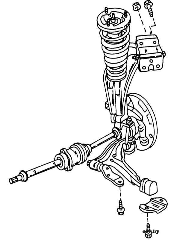
As you can see from the illustration, the new front suspension developed by Nissan has an unusual appearance. Although used shock absorbers with springs and hydraulic shock absorbers, the underside of the shock strut is equipped with a mount that is commonly used on a rear shock absorber. Removal and installation is very easy thanks to this design solution.
It should be remembered that shock absorber cannot be disassembled, i.e. if the shock absorber has lost its shock-absorbing properties, the entire strut should be replaced.
The order of work to remove the front spring and shock absorber Nissan Primera
Raise the front of the car and place it on the stands.
Set under wishbone lift and raise it slightly.
From the inside of the engine compartment, loosen the three nuts that hold the shock strut to the support at the top. Do not remove the nut in the middle as it holds the strut assembled. In case of replacement of parts of the shock absorber strut, it can be unscrewed.
Loosen the bolt and nut on the underside of the shock strut, knock out the bolt and release the strut.
Lower the lift slowly while disengaging the steering knuckle from the shock strut.
Dismantling the Nissan Primera strut
If it is necessary to disassemble the shock absorber before starting work, the following points must be taken into account:
The coil springs of the various models described in this manual differ from each other. In addition, different springs are installed depending on the installed motor. Keep this in mind when ordering new parts. The springs are color coded. Also, the springs should not be confused in places if both springs are removed.
The strut cannot be disassembled to replace the shock absorber. If the shock absorption properties are lost or the piston rod is worn out, the entire shock strut should be replaced.
When replacing the coil spring, make sure that no dirt gets into the shock absorber strut.
Never clamp the strut in a vise, but make a plate to which the strut can be screwed. The plate can be clamped in a vice.
The illustration below shows the replacement parts of the shock absorber strut.
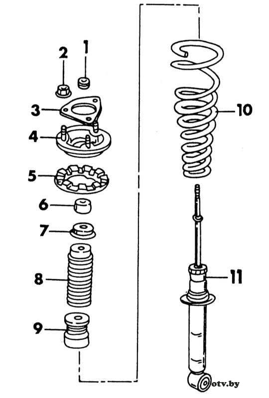
1 - upper rubber bushing
5 - upper rubber cushion
6 - upper rubber bushing
A spring compressor is required for disassembly.
The procedure for disassembling the Nissan Primera shock absorber strut
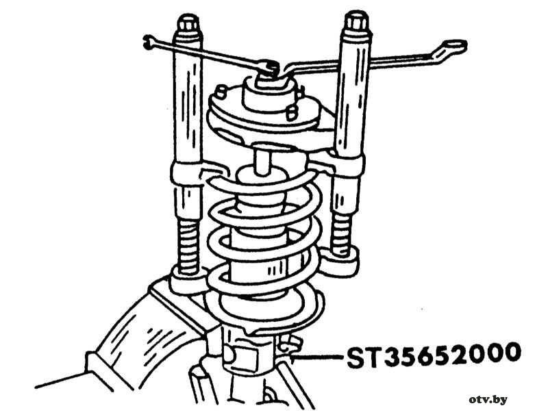
Referring to the illustration below, compress the spring until the upper strut support can be rotated by hand. For this, two clamping hooks can be used.
Loose piston rod nut.The spring is compressed by a compressor and a wrench is used to hold the stem.
Loosen the piston rod nut on the inside of the upper support while holding the piston rod with a wrench as shown in the illustration.
Based on the illustration, remove all upper support parts and then the coil spring from the shock strut. Be careful not to scratch or damage the piston rod.
Nissan Primera suspension strut assembly
Assemble the strut using the illustration as follows:
The procedure for assembling the Nissan Primera strut
First you need bleed shock absorbers... Displace air from the shock absorber by moving the piston up and down several times, while the piston must go through its entire stroke each time. Pull out piston rod with knuckle side down. Push in the piston with the knuckle side up.
Compress the spring with a compressor and slide it onto the shock strut. Make sure it fits correctly in the cup.
Slide all the parts shown in the illustration onto the shock strut in order. Slide the compression stroke buffer, dust cup and cup over the piston rod in the correct direction. Before you can put on the upper strut support, you need to find a notch on the outer circumference. Install the support so that the notch with the shock absorber strut is facing the inside of the vehicle. In this regard, pay attention to the fastening of the shock absorber. An arrow is embossed in it, which on the left side should be facing backward, and on the right side forward. The notch and arrow should be oriented relative to each other.
Screw on a new piston rod nut, holding the rod as shown in the illustration and tighten the nut to 18 - 24 N • m.
Release the spring compressor slowly and check that the spring fits into the cup on the shock strut.
Nissan Primera suspension strut installation
Installation of the shock absorber is carried out in the reverse order of removal. Make sure that the brake hose is not kinked when connecting.
The procedure for performing work on the installation of a shock absorber Nissan Primera
After installation, turn the steering wheel from lock to lock and check that the hose does not run into any part of the car. The tightening torques are given in the Specifications at the beginning of the Chapter.
Tighten the three nuts of the upper support of the shock absorber on the body mount to 45 - 53 N • m. Hammer in the shock absorber bolt on the underside to the wishbone.
Finally bleed the brake systemif the brake hose has been disconnected.
Nissan Primera operation manual, maintenance and repair manual, wiring diagrams, body control dimensions with petrol engines: GA16DE 1.6 l (1597 cm³) 99 hp / 73 kW, QG18DE 1.8 l (1769 cc) 114 hp / 84 kW, SR20DE 2.0 l (1998 cc) 122-150 hp / 90-110 kW and diesel CD20T 2.0 l (1974 cc) 90 hp / 66 kW. Nissan Primera P11 station wagon, sedan and hatchback models from 1995 to 2001
Nissan Primera Р11-144 represents an updated version of the model, which appeared on sale at the end of 1999, and belongs to class O. The second generation differs from the previous version by the original design of all three body types: sedan, hatchback and station wagon. The front part of the body, while retaining the external resemblance to its predecessor, received an elongated hood, narrower headlight units and a bumper integrated with the body. The model has become a little longer. The overall length of sedan and hatchback vehicles has been increased by 92 mm, and the station wagon - by 63 mm.
Powertrains include four engines with a displacement of 1.6-2.0 liters, including three gasoline and one turbocharged diesel.A new engine in this series is the QG18DE gasoline engine with a volume of 1.8 liters and a capacity of 114 hp, equipped with a variable valve timing, which ensures its high flexibility in operation and efficiency. The most powerful of the petrol engines SR20DE is equipped with both a manual transmission and an automatic continuously variable automatic transmission CVT or CVT-M6 with the possibility of manual gear shifting (variator). The complete set with a variator is considered a very good solution by Nissan.
This manual is intended to enable the car enthusiast to discuss and plan car repairs with a professional mechanic, or to do it on his own. The manual will help you determine what work needs to be done (even if you decide that you can do it in the workshop), diagnose and provide information about the technical condition, determine the sequence of actions and diagnostics during maintenance or repair. Nevertheless, we hope that you will use this Manual just for the independent work.
Simple work will take much less time than servicing a car in a workshop, where you need to come twice to drop off and pick up the car. And, of course, most importantly, you can save a little money that will be spent on paying for the work. A good set of metric wrenches, screwdrivers, and dipsticks is essential for maintenance and repairs, as these are the simplest hand tools used for most jobs. Sometimes repairs require special tools or special training. This is indicated in the warnings in this manual. Drawings and descriptions are included in this manual showing the function of the various parts and their locations. The works are described and photographed in a step-by-step sequence, so that even a beginner can complete them.
The manual is divided into 11 Sections. Sections are divided into Parts and Chapters. There are many illustrations, especially those parts that give a detailed sequence of operations to be performed. The text is accompanied by explanatory illustrations. They are numbered in decimal numbers in accordance with the chapter number and the number of the chapter in it, for example: 6.4 - the illustration refers to point 4 of Chapter 6. At the beginning of the manual there is a detailed Contents, which can easily find the question you are interested in. The "left" or "right" of the vehicle is considered in relation to the person sitting in the driver's seat facing forward. Unless otherwise stated, nuts and bolts are loosened by turning counterclockwise and tightened by turning clockwise. Manufacturers are constantly modifying vehicles with changes to specifications, specifications and recommendations, and upon notification, we will update our Guidelines as soon as possible.
The store offered me a set of bearings.
Gathering my courage I take off the wheel.
Remove the cap on the lever.
We unscrew the bolt fastening to the upper arm.
Next, the stabilizer post and the amartizer bolt.
After the nut that actually holds the middle lever on the fist.
And here I was disappointed. No matter how I tried, I could not find any backlash. Everything is okay. Everything sits rigidly. Well, okay, I took it off so I took it off. Knock the lever out of the swivel fist by tapping lightly from the bottom.
This is a bottom bearing without oil seal and protection.
This is a bearing ring. I took it off and filled it with fresh grease.
Put back the ring and the oil seal.
Collected everything in reverse order. And I found a knock in the upper levers. And replaced the steering tip. Now to the collapse.
You can tell me whatever you want, but I will still use LPG as fuel.

Well, how did I deal with the problem of leverage
———- Post added at 22:49 ———- Previous post posted at 22:47 ———-
———- Post added at 22:53 ———- Previous post posted at 22:49 ———-
look at FEBESTA, there are both levers and silent blocks separately, you have a FEBESTA warehouse somewhere in Kiev,
Good afternoon.
I took my Nissan with a mileage of 133 thousand. After the purchase, they said in the diagnostics that it was necessary to change the upper levers.
Took 555 - replacement by 135,000 km (06/01/08), by the way there were also 555, at the next examination they made the same diagnosis again, though almost three years later (04/16/2011) mileage of 166,660 km. Total 555 levers ran - 31 660 km (seems to be normal)
I took the SAFETY levers for replacement, the seller convinced that they are also Japanese, they run no worse than 555, and are not much cheaper. Just recently I drove to a service station for annual diagnostics, I think it's time for sure to look at the upper levers (today's (10.24.14) mileage is 202,500 km), the master said that the upper levers are normal, but the left middle lever is dead (steering knuckle bearings) ... So these SAFETYs have already run 35840 km, but they will probably die soon, and then we'll see.
———- Post added at 14:18 ———- Previous post posted at 14:17 ———-
By the way, I changed the salenblocks of the rear levers, put FEBESTOS, a year later they died.
———- Post added at 14:24 ———- Previous post posted at 14:18 ———-
Disassembled steering knuckle with hub bearing and drive shaft
1 - retaining ring, external
2 - hub bearing
3 - shield
4 - steering knuckle
5 - retaining ring, inner
6 - internal stuffing box
7 - drive shaft
8 - nut, 100 - 120 N • m
9 - wheel pin
10 - brake disc
11 - wheel bolt, 100 - 120 N • m
12 - cotter pin
13 - nut retainer
14 - nut of the hub bearing, 240 - 320 N • m
15 - washer
16 - wheel hub
17 - external stuffing box
18 - intermediate washer
Removing the hub and steering knuckle is also recommended if the drive shaft needs to be removed, whether for repairs, gearbox removal, or other work.
- Loosen the wheel nuts and the drive shaft nut while the vehicle is on its wheels.
- Place the front of the car on supports and remove the wheel.
- Remove the brake caliper. To do this, remove both bolts shown in the illustration below. Tie the brake caliper with a piece of wire to the front suspension. Do not allow the caliper to sag on the hose.
Both bolts shown by arrows hold the brake caliper.
- Remove the cotter pin from the tie rod castle nut, loosen the nut and use a suitable puller to separate the pivot from the steering arm (see illustration below). To avoid damaging the threads, you can screw the inverted nut onto your finger so that it is flush with the finger.
Pressing the tie rod ball pin out of the tie rod lever using a special puller.
- Loosen the nut on the upper side of the knuckle and remove the knuckle guide pin from the upper arm. As you can see, the connections are different from previous Nissan vehicles. Push the entire steering knuckle down until it is in the position shown in the illustration below.
- Thread the nut onto the drive shaft until the outside is flush with the shaft and hammer the shaft slightly with an alloy hammer inward to loosen it from the hub bearing.
- On the underside of the steering knuckle, remove the ball joint nut on the wishbone and separate the ball joint with a puller. The puller shown in the illustration below is also suitable for suspension ball joints.
Checking the fluid level in the servo compensation reservoir
- Remove the steering knuckle from the front suspension. Remove the brake disc.
- If the steering knuckle needs to be removed together with the drive shaft, drain the transmission oil (unscrew the plug and substitute a container).
- Press the drive shafts out of the transmission, as described in the Head Coupling and drive shafts for the left and right shafts, as well as for a manual or automatic transmission.
- Remove the hub, steering knuckle and drive shaft from the vehicle, or leave the drive shaft in the transmission and remove the steering knuckle with hub from the drive shaft.
Disassembly and replacement of the hub bearing
- Unscrew the hub nut completely and remove the drive shaft from the hub if it is still installed.
- Clamp the steering knuckle in a vise and knock out the hub with an alloy rod from the back. If the hub is knocked out of the steering knuckle, the hub bearing must always be replaced.The inner bearing race remains on the hub and must be removed with a suitable puller.
- Remove the retaining ring on the outside of the steering knuckle using pliers. On the back, pull out the gland with a screwdriver and remove the second retaining ring. The notches in the retaining ring facilitate the installation of the pliers.
- Place the knuckle under a press and press out the hub bearing from outside to inside. Use a piece of pipe to press out the bearing. Clean all parts thoroughly. The bearings must always be replaced together with the races, as they run in to each other. The steering knuckle can only be checked with a magnetic device.
Steering knuckle assembly
When installing the hub bearing and assembling the steering knuckle, proceed as follows:
- Thoroughly clean grease from the bore of the knuckle and the outside of the hub bearing, and insert the inner circlip into the groove in the knuckle.
- Press the new bearing from the outside into the steering knuckle until it rests against the circlip. When doing this, apply force to the outer race of the hub bearing.
- Insert the outer circlip into the groove. Check that the circlip fits flawlessly around its entire circumference.
- Lubricate the lips of both oil seals with grease and drive the front and rear into the steering knuckle without damaging them. Wipe off excess grease.
- Place the steering knuckle on the press table and press the hub into the bearing and steering knuckle. Be sure to ensure that the press-in pressure does not exceed 3 tons.
- The bearing preload should now be checked. To do this, place the steering knuckle on the press table and increase the load on the outer side of the hub to 3.5-5.0 tons. While holding the load, move the steering knuckle from side to side several times. The steering knuckle must turn without binding despite the load.
Installing the steering knuckle with the drive shaft is carried out in the reverse order. Always install a new circlip in the end of the drive shaft. Details on the installation of drive shafts are given in the Chapter Coupling and drive shafts. Align the spline well when installing the drive shafts in the differential. After installation, pull on the shaft to check that the ring snaps into place.
All tightening torques given in the Specifications at the beginning of the Chapter must be observed. Tighten the drive shaft nut to 240 - 320 N • m, install a retainer on the nut and insert a new cotter pin.
Nissan Primera P10, P11 Front Upper Arm Repair
Nissan Primera P11 steering knuckle bearing replacement
Nissan Primera P11 stove repair (part 2)
SQUEEPS - FRONT SUSPENSION KNOCKS
nissan premiere change drive oil seals and CV joints
spring spacer nissan example
We change the silent blocks. Removing the front levers
Replacing the front levers and stabilizer bar for Nissan Primera 2004 Nissan Primera
Replacing the struts and bushings of the front stabilizer on the Nissan Primera P12
Nissan Primera P10, P11 Front Upper Arm Repair
Upper arm Nissan primera p10 mileage 20,000 km
555 Primera P11 Upper Arm Lubrication
NISSAN Primera p10 front upper arm repair, bearing installation!
Replacing the front levers and stabilizer bar for Nissan Primera 2004 Nissan Primera
How to replace levers on a car. Replacement of levers Nissan Primera. Safety Brand
upper needle bearing Nissan RIMERA P10
We change the silent blocks. Removing the front levers
NISSAN PRIMERA P11- 144 Year 2000 Upper Arm Front Strut
We are not afraid, we climb, we twist! Suspension repair Nissan Primera
Repair Nissan Primera P11 Start There is Oil. All about oil
Repair Nissan Primera P11 do-it-yourself injector flushing at home
Elimination of oil on GA16DE / Engine repair / Nissan Primera P11
Repair Nissan Primera P11 injector failure open circuit.
Nissan Primera P11 steering knuckle bearing replacement
Nissan Primera P10, P11 Front Upper Arm Repair
Nissan Primera. Body repair. Part 1
SQUEEPS - FRONT SUSPENSION KNOCKS
Replacement of thresholds, bottom cooker for Nissan Sunny.
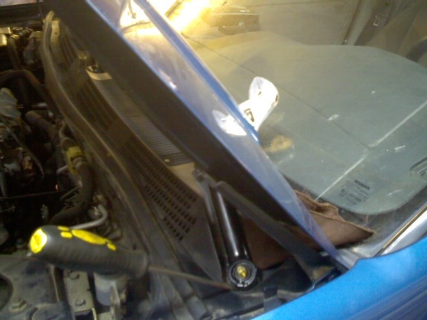
How to repair Nissan Primera P11 wipers:
- Unscrew the wipers themselves and the central screw.
- Then remove the self-tapping screws that secure the trim. It also needs to be removed.
- Use the "10" key to unscrew the motor mounts.
- With your hand in the hole, unscrew the nut that secures the gearbox itself to the trapezoid. Disconnect the connector before doing this.
- After removing the trapezoid, try removing its cover. Most likely, you will see melted plastic there, which will have to be removed. The magnetic circle can be cleaned and the contacts. Remove the plastic itself with a heated knife.
- Remove old grease from bushing. Do not forget to lubricate afterwards. The lubricant must be suitable for wet conditions.
- After the plastic has been removed and the lid is in place, it may be necessary to drill additional holes for the lid fasteners.
- Installation is done upside-down. The trapezoid will need to be pulled towards the driver, after which the nut will have to be tightened.
Nissan Primera P10, P11 Front Upper Arm Repair
Upper arm Nissan primera p10 mileage 20,000 km
Replacing the front levers and stabilizer bar for Nissan Primera 2004 Nissan Primera
SQUEEPS - FRONT SUSPENSION KNOCKS
We are not afraid, we climb, we twist! Suspension repair Nissan Primera
Normal day Nissan Primera P11
We change the silent blocks. Removing the front levers
How to replace levers on a car. Replacement of levers Nissan Primera. Safety Brand
Nissan Primera P11 steering knuckle bearing replacement
Replacing struts on the 1996 NISSAN Primera P11
Nissan Primera P10, P11 Front Upper Arm Repair
Replacing the front levers and stabilizer bar for Nissan Primera 2004 Nissan Primera
Upper arm Nissan primera p10 mileage 20,000 km
How to replace levers on a car. Replacement of levers Nissan Primera. Safety Brand
SQUEEPS - FRONT SUSPENSION KNOCKS
nissan primera steering knuckle bearing replacement
We are not afraid, we climb, we twist! Suspension repair Nissan Primera
Normal day Nissan Primera P11
Nissan example p12 removal and repair of the rear suspension strut
We change the silent blocks. Removing the front levers
We are not afraid, we climb, we twist! Suspension repair Nissan Primera
Repair Nissan Primera P11 Start There is Oil. All about oil
Repair Nissan Primera P11 do-it-yourself injector flushing at home
Elimination of oil on GA16DE / Engine repair / Nissan Primera P11
Repair Nissan Primera P11 injector failure open circuit.
Nissan Primera P11 steering knuckle bearing replacement
Nissan Primera P10, P11 Front Upper Arm Repair
Nissan Primera. Body repair. Part 1
SQUEEPS - FRONT SUSPENSION KNOCKS
Replacement of thresholds, bottom cooker for Nissan Sunny.
Nissan Primera P10, P11 Front Upper Arm Repair
Upper arm Nissan primera p10 mileage 20,000 km
555 Primera P11 Upper Arm Lubrication
NISSAN Primera p10 front upper arm repair, bearing installation!
Replacing the front levers and stabilizer bar for Nissan Primera 2004 Nissan Primera
How to replace levers on a car. Replacement of levers Nissan Primera. Safety Brand
upper needle bearing Nissan RIMERA P10
We change the silent blocks. Removing the front levers
NISSAN PRIMERA P11- 144 Year 2000 Upper Arm Front Strut
| Video (click to play). |


