In detail: do-it-yourself yamz 236 pump repair from a real master for the site my.housecope.com.
ORDER OF REMOVAL AND DISASSEMBLY OF THE WATER PUMP of YAMZ-236 engines
1. Having loosened the fastening of the tensioner of the belt drive of the water pump, remove the belt from the pulley of the water pump.
2. Drain the coolant from the engine and radiator.
3. Remove the inlet 8 from the water pump.
4. After unscrewing the mount, remove the water pump from the engine, carefully not damaging the gasket.
5. Unscrew the nuts 14 (Fig. 13) of the branch pipe 8.
6. Slightly tapping on the protruding parts of the branch pipe 8 in the direction of arrows B, remove the indicated branch pipe from the pump housing 1.
7. Lock impeller 2 (or pulley 10) against rotation with shaft 5.
8. Unscrew plug 7 from the impeller threaded hole.
9. Screw the nut 17 of the extractor into the threaded hole (M22x1.5) of the impeller 2 (Fig. 14, 15) and, screwing in the bolt 18, press the impeller 2 off the shaft 5.
10. Bend back the "mustache" D of the mechanical seal housing 19 (Fig. 14) and remove the collar 20, bushing 21 and collar 22 with the spring and frame assemblies.
Rice. 13. Water pump:
1-building; 2-impeller; 3-face seal; 4-sleeve; 5-shaft; 6-spillway; 7-plug; 8-inlet pipe; 9-retaining ring; 10-pulley; 11, 12-o-rings; 13-bearings; 14, 15-nuts and spring washers.
11. Using a puller, press the pulley 10.
12. Remove the circlip 9 from the groove in the pump casing 1.
13. Press out the shaft 5 from the housing 1 with a sprinkler 6 and bearings 13 (see Fig. 13).
14. If the brass body 23 of the mechanical seal is not damaged, it is not necessary to remove it from the body 1 and at this the pump disassembly can be considered complete (see Fig. 14).
| Video (click to play). |
The cooling system of the YaMZ-236 engine for Ural and Maz vehicles, for the T-150 tractor is liquid, circulating.
The cooling system includes a water pump, fan, thermostats, a remote thermometer, and a frame-mounted radiator.
During the operation of the YaMZ-236 engine of the Ural, Maz cars, the T-150 tractor, the circulation of the coolant in the cooling system is created by a centrifugal pump.
From the discharge pipe of the pump, through the channels in the cover of the distribution gears, the liquid under pressure enters the water jacket of the left row of cylinders and the right row of the cylinder block, then into the cylinder heads and collects in the drainage pipes.
In the water jackets of the cylinder heads, the liquid is supplied through the guide channels, primarily to the most heated surfaces - the outlet pipes and nozzle cups.
From the drainage pipelines, the heated liquid is fed through thermostats to the radiator, where it gives off heat to the air flow created by the fan, after which it goes back to the YaMZ-236 water pump.
When the coolant temperature drops, thermostats automatically direct all coolant flow directly to the water pump, bypassing the radiator. Thus, by means of thermostats, the optimal thermal mode of the engine operation is ensured.
The YMZ-236 centrifugal water pump is installed in the front part of the engine of Ural, Maz, T-150 tractor and is driven by a V-belt from a pulley mounted at the front end of the crankshaft.
An impeller pressed onto the roller rotates in a cast-iron housing. The pump shaft is supported by two ball bearings with a one-way seal. When assembling the pump, the bearing cavity is filled with Litol grease for the entire service life of the pump without additional lubrication.
The pump cavity is sealed along the end surfaces. To control the tightness of the mechanical seal, there is a drain hole in the pump casing.
The water pumps installed on YaMZ-236 engines have significant structural differences between themselves and are not interchangeable with each other:
- The water pump of YaMZ-236N, B engines (Fig. 21) is marked on the body 236-1307010-A3.
- The water pump of the YaMZ-236NE, HE2, BE, BE2 engines is marked on the body 236-1307010-B1.
Fig. 21. Water pump of the YaMZ-236 engine
1 - case; 2 - nipple; 3 - roller; 4 - ball bearings; 5 - retaining ring; 6 - bushing; 7 - pulley; 8.10 - nuts; 9 - lock washer; 11 - an adjusting gasket; 12 - hairpin; 13 - spillway; 14 - body bushing; 15 - retaining ring; 16 - a thrust ring; 17 -
sealing ring; 18 - impeller mounting nut; 19 - oil seal cuff; 20 - spring; 21 - impeller; 22 - housing cover.
Maintenance of the cooling system of the YaMZ-236 diesel engine
The efficient operation of the cooling system of the YaMZ-236 engine of the Ural, Maz cars, the T-150 tractor largely determines the efficiency, reliability, service life and other indicators of the engine.
To ensure normal engine operation, comply with the following requirements:
Fill the cooling system of the YaMZ-236 engine with the recommended special low-freezing fluids or, in exceptional cases, for a short time with clean soft water.
Pour coolant through a funnel with a sieve, using clean dishes.
Observe the temperature of the coolant, maintaining it within the range of 75 - 90 ° C.
In order to avoid the appearance of deformations of the heads and jacket of the cylinder block, add the coolant to the cooling system of a heated engine gradually and always during its operation.
If the cooling system of the YaMZ-236 engine of Ural, Maz, tractor T-150 is filled with water, then regularly rinse the cooling system with clean water using a special flushing gun, and in its absence - with a strong stream of clean water, preferably pulsating. Systematically descale the cooling system.
When using antifreeze as a coolant, it is necessary to periodically monitor its color. If the antifreeze acquires a red-brown color, then this indicates its aggressiveness in relation to the structural materials of engine parts.
In this case, the antifreeze must be replaced by flushing the cooling system before this.
Monitor the serviceability of the mechanical seal of the impeller of the water pump, bearing in mind that coolant seeping into the bearings of the water pump destroys them.
A malfunction of the mechanical seal is evidenced by the leakage of water from the drain hole on the water pump housing, which must not be plugged. A pump with a defective seal must be repaired.
In case of violation of the temperature regime, check the serviceability of the thermostats and their gaskets.
The opening temperature of the main thermostat valve should be 80 ± 2 ° C (indicated on the thermostat body). The valve must open fully, moving at least 8 mm from its seat. Replace the defective thermostat with a new one.
Water pump for YaMZ-236 engines - disassembly and assembly
Peculiarities of disassembly and assembly of a water pump installed on YaMZ-236 engines of Ural and Maz vehicles, and a T-150 tractor.
Fig. 22. Water pump of the YaMZ-236 engine
1 – building; 2 – impeller; 3 – face seal; 4-sleeve; 5 - shaft; 6 – spillway; 7 – plug; 8 – inlet branch pipe; 9 – retaining ring; 10 – pulley; 11, 12 - sealing rings; 13 – bearings; 14, 15 – fastening nuts and spring washers.
Dismantling the water pump (pump) YAMZ-236
Having loosened the fastening of the tensioner of the belt drive of the water pump (pump) YAMZ-236, remove the belt from the pulley of the water pump.
Drain coolant from engine and radiator.
Remove inlet pipe from water pump.
After unscrewing the mount, remove the water pump from the engine without carefully damaging the gasket.
Unscrew the nuts 14 (Fig. 22) of the branch pipe 8.
Lightly tapping on the protruding parts of the branch pipe 8 in the direction of arrows B, remove the specified branch pipe from the pump housing 1.
Secure impeller 2 (or pulley 10) against rotation with shaft 5.
Unscrew plug 7 from the threaded hole of impeller 2.
Screw the nut 17 of the stripper into the threaded hole (M22x1.5) of the impeller 2 and, screwing in the bolt 18, press the impeller 2 off the shaft 5.
Fold back the "mustache" D of the mechanical seal housing 19 and remove the collar 22 with the spring and frame assemblies.
Using a puller, press the pulley 10.
Remove circlip 9 from the groove in pump casing 1.
Press out shaft 5 with a sprinkler 6 and bearings 13 from the housing 1.
If the brass body 23 of the mechanical seal is not damaged, it may not be removed from the body 1, and at this the pump disassembly can be considered complete.
Wash all the parts of the water pump of the YaMZ-236 engine of Ural, Maz vehicles, the T-150 tractor and dry with compressed air.
Press bearings 13 and a water distributor 6 onto shaft 5 (Fig. 22).
- pre-lubricate shaft 5 with diesel oil;
- install bearings 13 so that the sealing washers are on the outside;
- press-on force is applied to the inner ring of the bearing.
Fig. 23. Dismantling of the YaMZ-236 water pump
2 – impeller; 9 – retaining ring; 10 – pulley; 17 – puller nut; 18 – puller bolt; 19 – body of mechanical seal; 20 – sleeve collar; 21 – seal sleeve; 22 – cuff with spring, assembled.
Fill the entire cavity between the bearings with Litol grease (60. 70 g).
Press the shaft complete with bearings and spill-over device into housing 1 up to the stop.
- pre-lubricate the bore of housing 1 for bearings with clean engine oil;
- Apply pressing force to the outer ring of the bearing.
Install the circlip 9 into the groove of the water pump housing of the YaMZ-236 engine. Press the pulley 10 onto the shaft 5 until it stops.
- pre-lubricate the shaft with clean engine oil;
- provide a fixed stop for the opposite end of the shaft.
Install in the brass body 19 (Fig. 23) the parts of the mechanical seal of the YaMZ-236 pump;
- rubber cuff 22 assembled with a spring and spring frames;
- reinforced collar 20 and sealing sleeve 21. Install rubber sleeve 23 and sealing sleeve 21 into impeller 2.
- preliminarily put the collar 23 on the sealing sleeve 21;
- Apply a thin layer of grease to the bore of the impeller 2 and to the outer surface of the rubber cuff 23;
- take the cuff assembly with the sleeve with both hands and, applying force to the end of the sealing sleeve, insert these parts into the impeller bore until they stop, avoiding distortions.
Press the pump impeller of the YaMZ-236 engine complete with a collar and a sealing sleeve onto shaft 5 (Fig. 22).
- pre-lubricate shaft 5 with clean engine oil;
- provide a fixed stop on the opposite end of the shaft;
- install the impeller on the shaft in the size 10-0.15 mm (Fig. 22) between the end of the shaft and the end of the impeller hub. To do this, when pressing in, install a disk with a diameter of no more than 13 mm and a height of 10-0.15 mm on the end of the shaft.
Secure impeller 2 (or pulley 10) against rotation. Screw the plug 7 into the threaded hole of the impeller 2 until it stops;
Install bushing 4 and rubber ring 12 into housing 1.
Install the rubber ring 11 into the groove of the branch pipe 3, preventing it from twisting.
Press the branch pipe 3 into the bore of the body 1 until it stops.
- pre-lubricate the bore in the housing 1 and ring 11 with a thin layer of Litol grease;
- the pins on the body 1 must freely enter the fastening holes of the branch pipe 8.
Secure the branch pipe 3 with nuts 14 with spring washers 15.
Check the quality of assembly by rotating the shaft 5 by the pulley 10. The rotation of the shaft must be free, without jamming.
A typical malfunction of the water pump is the flow of water through the impeller oil seal as a result of the wear of the textolite ring. A malfunction of the stuffing box seal is evidenced by the leakage of water from the drain hole on the water pump housing, which can be eliminated by turning the textolite ring upside down (not worn) to the end of the sleeve pressed into the housing, or by replacing the ring with the simultaneous replacement of the rubber cuff.
Blockage of the drain hole to eliminate leakage of the stuffing box is not allowed, as water seeping from the pump enters the bearings and destroys them.
To repair the stuffing box packing, you must:
- remove the water pump from the engine; unscrew the nuts securing the housing cover, remove the cover and gasket;
- while holding the roller by the pulley from turning, unscrew the cap nut and remove the impeller from the pump roller with a puller, remove the impeller seal retaining ring and remove all the seal parts from it.
The suitability of the stuffing box parts is determined by visual inspection. The textolite ring should not have chips or cracks or scoring on the working surface. Minor scuffing marks and risks are eliminated by lapping the ring. The stuffing box collar must be elastic, without tears, fit snugly to the shaft and the textolite ring.
The impeller oil seal should be assembled in the following order:
- insert the gland spring into the impeller housing, then the rubber gland complete with inner and outer cages, textolite and gland retaining rings. After installing the retaining ring, the textolite should move freely along the grooves of the impeller when pressed by hand and return to its original position under the action of the spring.
The part of the pump shaft, on which the rubber cuff sits, must be lubricated with soap before installing the impeller, and the end face of the sleeve, which is in contact with the textolite ring, with a thin layer of graphite grease. This eliminates the possibility of scuffing the working surface of the cuff and improves the quality of grinding in the working surfaces of the textolite ring and the end of the sleeve. After installing the impeller in place, the cap nut of the impeller fastening must be tightened to the full and secured with a washer.
When the pump is completely disassembled to replace the bearings and roller, the impeller is removed from the pump roller, as indicated above;
- unscrew the pulley fastening nut and remove the pulley from the pump shaft using a puller;
- unscrew the fastening screws and remove the bearing cover;
- remove the roller assembly with bearings and bushings from the pump housing.
In the presence of cracks of any size and location, the housing is not repaired, but replaced. During repair, felt oil seals are replaced with new ones, having previously impregnated them with grease.
Assemble the pump in reverse order. The body cavity between the ball bearings must be filled with lithol-24 or CIATIM-201 grease. After assembly, add grease through the oiler until grease appears from the control hole. After assembly, the pump roller should rotate freely, without jamming.
When installing the pump on the motor, it is recommended to replace the gasket between the pump flange and the timing gear cover. The seating surfaces of the pump flange and the roof of the distribution gears must be pre-cleaned from the remnants of the old gasket, and the new one must be greased on both sides with a non-drying sealing paste.
- Water pump, assy 236-1307010-A3
- Washer 252136-P2
- Nut 250513-P29
- Gasket 236-1307048-A
- Hairpin 216259-P29
- Roller spreader 201-1307026-A
- Ball bearing 160703 4619335067
- Roller 236-1307023-B2
- Key 4598246257
- Spacer bushing 236-1307111
- Ring 236-1307081
- Pulley 236-1307212-B3
- Pulley hub 236-1307216-B
- Hairpin 310403-P29
- Adjusting pulley gasket 236-1307222-B
- Pulley sidewall 236-1307218-B3
- Washer 252135-P2
- Stud nut 250510-P29
- Pulley fastening nut 250636-P29
- Washer 312536-P29
- Water pump housing, assy 236-1307014-G
- Body bushing 236-1307017-B
- Ring 034-038-25-2-1 2531112082
- Bypass nipple 236-1306082
- Hairpin 216258-P29
- Case 236-1307015-G
- Hairpin 216233-P29
- Cuff, large and small cuff clips, thrust ring and cuff spring 236-1307029
- Thrust ring 236-1307035-A3
- Cup 240-1307038
- Large cuff holder 240-1307036
- Small cuff holder 201-1307037
- Spring 201-1307034-A
- Cuff impeller, assy 236-1307030-B
- Retaining ring 236-1307033
- Cuffed impeller 236-1307032-B
- Belt 2564111404
- Washer 312484-P
- Cap nut 312115-P
- Ring 089-095-36-2-1 2531112198
- Housing cover 236-1307045-B
- Nut 250511-P29
- Washer 252135-P2
We invite regional dealers, representatives of service centers and online stores to cooperate!
Having loosened the fastening of the tensioner of the belt drive of the water pump (pump) YAMZ-238, remove the belt from the pulley of the water pump.
Drain coolant from engine and radiator.
Remove inlet pipe from water pump.
After unscrewing the mount, remove the water pump from the engine without carefully damaging the gasket.
Unscrew the nuts 14 (Fig. 3) of the branch pipe 8.
Lightly tapping on the protruding parts of the branch pipe 8 in the direction of arrows B, remove the specified branch pipe from the pump housing 1.
Secure impeller 2 (or pulley 10) against rotation with shaft 5.
Unscrew plug 7 from the threaded hole of impeller 2.
Screw the nut 17 of the stripper into the threaded hole (M22x1.5) of the impeller 2 and, screwing in the bolt 18, press the impeller 2 off the shaft 5.
Fold back the "mustache" D of the mechanical seal housing 19 and remove the collar 22 with the spring and frame assemblies.
Using a puller, press the pulley 10.
Remove circlip 9 from the groove in pump casing 1.
Press out shaft 5 with a sprinkler 6 and bearings 13 from the housing 1.
If the brass body 23 of the mechanical seal is not damaged, it may not be removed from the body 1, and at this the pump disassembly can be considered complete.
Wash all parts of the water pump of the YaMZ-238 engine and dry with compressed air.
Press on shaft 5 (Fig. 3) bearings 13 and a water distributor 6.
In this case, it is necessary: pre-lubricate shaft 5 with diesel oil;
? install bearings 13 so that the sealing washers are on the outside;
? the pressing force is applied to the inner ring of the bearing.
Rice. 3. Dismantling of the YaMZ-236 water pump: 2-impeller; 9-retaining ring; 10-pulley; 17-nut of a puller; 18-bolt puller; 19-body of mechanical seal; 20-sleeve sleeve; 21-bush seal; 22-cuff with spring assy.
Fill the entire cavity between the bearings with Litol-24 grease (60.70 g).
Press the shaft complete with bearings and spill-over device into housing 1 up to the stop.
? pre-lubricate the bore of housing 1 for bearings with clean engine oil;
? the pressing force is applied to the outer ring of the bearing.
Install the circlip 9 into the groove of the water pump housing of the YaMZ-236 engine. Press the pulley 10 onto the shaft 5 until it stops.
? pre-lubricate the shaft with clean engine oil;
? provide a fixed stop on the opposite end of the shaft.
Install in the brass body 19 (Fig. 3) the parts of the mechanical seal of the YaMZ-236 pump;
? rubber cuff 22 assembled with a spring and spring frames;
? reinforced collar 20 and sealing sleeve 21. Install rubber sleeve 23 and sealing sleeve 21 into impeller 2.
? preliminarily put the collar 23 on the sealing sleeve 21;
? apply a thin layer of grease to the bore of the impeller 2 and to the outer surface of the rubber cuff 23;
? take the cuff assembly with the sleeve with both hands and, applying force to the end of the sealing sleeve, insert these parts into the impeller bore until they stop, avoiding distortions.
Press the pump impeller of the YaMZ-236 engine complete with a collar and a sealing sleeve onto shaft 5 (Fig. 2).
? pre-lubricate shaft 5 with clean engine oil;
? provide a fixed stop on the opposite end of the shaft;
? install the impeller on the shaft in a size of 10-0.15 mm (Fig. 2) between the end of the shaft and the end of the impeller hub. To do this, when pressing in, install a disk with a diameter of no more than 13 mm and a height of 10-0.15 mm on the end of the shaft.
Secure impeller 2 (or pulley 10) against rotation. Screw the plug 7 into the threaded hole of the impeller 2 until it stops;
Install bushing 4 and rubber ring 12 into housing 1.
Install the rubber ring 11 into the groove of the branch pipe 3, preventing it from twisting.
Press the branch pipe 3 into the bore of the body 1 until it stops.
? pre-lubricate the bore in the housing 1 and ring 11 with a thin layer of Litol grease;
? the pins on the body 1 must freely enter the fastening holes of the branch pipe 8.
Secure the branch pipe 3 with nuts 14 with spring washers 15.
Check the quality of assembly by rotating the shaft 5 by the pulley 10. The rotation of the shaft must be free, without jamming.
Dismantling of the YaMZ-238 water pump
Unscrew the nuts 14 (Figure 5) of the branch pipe 8.
Lightly tapping on the protruding parts of the branch pipe 8 in the direction of arrows B, remove the specified branch pipe from the pump housing 1.
Fig. 5 - Water pump (pump) YaMZ-238 D, DE, AK, M2, B, ND
1 – building; 2 – impeller; 3 – face seal; 4-sleeve; 5 – shaft; 6 – spillway; 7 – plug; 8 – inlet branch pipe; 9 – retaining ring; 10 – pulley; 11, 12 - sealing rings; 13 – bearings; 14, 15 – fastening nuts and spring washers.
Secure impeller 2 (or pulley 10) against rotation with shaft 5.
Unscrew plug 7 from the threaded hole of impeller 2.
Screw the nut 17 of the stripper 16 (Figure 6) into the threaded hole (M22x1.5) of the impeller 2 (Figure 6) and, screwing in the bolt 18, press the impeller 2 off the shaft 5.
Bend back the "mustache" of the mechanical seal housing 19 (Figure 6) and remove the collar 22 with the spring and frames as an assembly.
Using puller 16, press off pulley 10.
Remove circlip 9 from the groove in pump casing 1.
Press out shaft 5 with a sprinkler 6 and bearings 13 from the housing 1.
If the brass body 23 of the mechanical seal and the bushing 4 are not damaged, they can not be removed from the body 1 and the disassembly of the pump can be considered complete.
Figure 6 - Disassembly of the water pump YaMZ-238DE2, 238B, 238DE
2 – impeller; 9 – retaining ring; 10 – pulley; 17 – puller nut; 18 – puller bolt; 19 – body of mechanical seal; 20 – sleeve collar; 21 – seal sleeve; 22 - cuff with a spring, assy
Assembling a water pump YAMZ-238DE2, 238ND5, 238AK
Wash all pump parts and dry with compressed air.
Press the bearings and the splash valve onto the shaft. In this case, it is necessary to: pre-lubricate the shaft with diesel oil; the pressing force is applied to the inner ring of the bearing;
Fill the entire cavity between the bearings with Litol-24 grease (60-70 g).
Press the shaft complete with bearings and spill-over device into housing 1 up to the stop. In this case, it is necessary to: pre-lubricate the bore of housing 1 for bearings with clean engine oil; the pressing force is applied to the outer ring of the bearing.
Place the circlip 9 in the groove in the housing 1.
Press pulley 10 onto shaft 5 until it stops. It is necessary to: pre-lubricate the shaft of the YaMZ-238 D, DE, AK, M2, B, ND water pump with clean engine oil; provide a fixed stop on the opposite end of the shaft.
Install the mechanical seal parts into the brass body; rubber cuff assembled with spring and spring frames; reinforced collar and sealing sleeve.
Install the rubber collar and the grommet into the impeller. In this case, it is necessary:
- first put the cuff on the sealing sleeve;
- Apply a thin layer of grease to the bore of the impeller 2 and to the outer surface of the rubber cuff 23;
- take the cuff assembly with the sleeve with both hands and, applying force to the end of the sealing sleeve, insert these parts into the impeller bore until they stop, avoiding distortions.
Press impeller 2 complete with collar and sealing sleeve onto shaft 5. In this case:
- pre-lubricate shaft 5 with clean engine oil;
- provide a fixed stop for the opposite end of the pump shaft 238DE2, 238ND5, 238AK;
- install the impeller on the shaft in a size of 10-0.15 mm between the end of the shaft and the end of the impeller hub. To do this, when pressing in, install a disk with a diameter of no more than 13 mm and a height of 10-0.15 mm on the end of the shaft.
Secure impeller 2 (or pulley 10) against rotation.
Screw the plug 7 into the threaded hole of the impeller 2 until it stops;
Install bushing 4 and rubber ring 12 into housing 1.
Install the rubber ring 11 into the groove of the branch pipe 3, preventing it from twisting.
Press the branch pipe 3 into the bore of the body 1 until it stops. In this case, it is necessary to: pre-lubricate the bore in the housing 1 and ring 11 with a thin layer of Litol-24 grease; the pins on the body 1 must freely enter the fastening holes of the branch pipe 8.
Secure the branch pipe 3 with nuts 14 with spring washers 15.
Check the quality of assembly by rotating the shaft 5 by the pulley 10. The rotation of the shaft must be free, without jamming.
Installation of a pump belt 238DE2, 238B, 238DE
Install the tensioner on the water pump housing and secure with two bolts (M12, 310098-P29, 2 pcs.) Washers (312672-P29, 2 pcs.) With Mcr = 78.45-107.87 Nm (8-11 kg / cm ) (S = 17).
Loosen the adjusting bolt (201682-P29) on the tensioner, install the belt in the grooves of the water pump pulley, move the tensioner assembly down and check the belt tension with the device.
Most often, due to their great demand, the YaMZ-236/238 pumps are used, the parameters and indicators of which are ideally suited for Yaroslavl engines with the same index and their analogues.
The capacity of such a pump is about 30 liters per minute with a torque on the pump shaft of 0.52 units. The weight usually does not exceed 9 kg, and as for the dimensions, they may differ depending on the purpose.
Consultation on technical issues, purchase of spare parts 8-916-161-01-97 Sergey Nikolaevich
The pump shaft must turn freely and without jamming, even if this rotation is performed by hand, acting on the pulley or impeller of the pump.
4.4. Subdivision of water and oil pumps of engines YaMZ-7601.10, YaMZ-7514.10, YaMZ-7513.10, YaMZ-7512.10, YaMZ-7511.10
WATER PUMP ASSEMBLY.
1. Unscrew the nuts 14 (Fig. 81) of the branch pipe 8.
2. Slightly tapping on the protruding parts of the branch pipe 8 in the direction of arrows B, remove the indicated branch pipe from the pump housing 1.
3. Secure impeller 2 (or pulley 10) against rotation with shaft 5.
4. Unscrew the plug 7 from the threaded hole of the impeller 2.
5. Screw the nut 17 of the puller 16 (Fig. 82) into the threaded hole (M22 × 1.5) of the impeller 2 and, screwing in the bolt 18, press the impeller 2 off the shaft 5.
6. Bend back the "whiskers" of the mechanical seal housing 19 (Fig. 82) and remove the collar 22 with the spring and frame assemblies.
7. Using the puller 16, press the pulley 10.
8. Remove the circlip 9 from the groove in the pump casing 1.
9. Press out the shaft 5 from the housing 1 with a sprinkler 6 and bearings 13.
10. If the brass body 23 of the mechanical seal and the sleeve 4 are not damaged, they can not be removed from the body 1 and the pump disassembly can be considered complete.
Rice. 81 - the Water pump
1 – building; 2 – impeller; 3 – face seal; 4-sleeve; 5 – shaft; 6 – spillway; 7 – plug; 8 – inlet branch pipe; 9 – retaining ring; 10 – pulley; 11, 12 O-rings; 13 – bearings; 14, 15 – fastening nuts and spring washers.
Rice. 82 - Dismantling the water pump
2 – impeller; 9 – retaining ring; 10 – pulley; 17 – puller nut; 18 – puller bolt; 19 – body of mechanical seal; 20 – sleeve collar; 21 – seal sleeve; 22 – cuff with spring, assembled.
The design of the device for disassembling the water pump is shown in Fig. 83.
Rice. 83 - Puller
OIL PUMP ASSEMBLY.
Rice. 84 - Oil pump drive gear puller
1 – sponge; 2 – traverse; 3 – screw; 4-knob.
1. Clamp the oil pump casing in a vise by the surfaces P1 and P2 (Fig. 23), having previously installed protective plates on the vise jaws so as not to damage the pump casing.
2. Unscrew the stop flange 9 (Fig. 23) and remove it (S = 46). The flange has a left-hand thread and must be turned in the direction of the arrow in Fig. 23.
3. Remove the idler gear.
4. Using a puller (Fig. 84), press the oil pump drive gear 7 (Fig. 23) and remove the key 8 (Fig. 23). If necessary, clean the edges of the keyway.
5. Unscrew the bolts of the intermediate gear axle 2 (Fig. 23) and remove it (S = 17).
6. Unscrew the fastening bolts 10 and the cover of the oil pump housing with bushings assembled 4 (Fig. 23) (S = 12). Remove the drive pinion shaft 3 and the driven pinion shaft 5 from the oil pump housing (Fig. 23).
7. Disassemble the pressure reducing valve by unscrewing the plug (S = 32) and removing the washer, spring, valve, gasket from the body.
Our company sells spare parts for various types of special equipment, trucks and agricultural equipment of domestic and foreign production, including spare parts for the YaMZ-238 engine. One of the directions of the enterprise's work is the repair and maintenance of engines, transmissions, steering, braking systems, running gear, hydraulic and electrical equipment. Working with us, you are guaranteed to receive an individual approach and expert advice, as well as high-quality spare parts and components at the lowest prices.
Repair of the cooling system of the YaMZ-238 engine
YaMZ-238 engine has a closed-type liquid circulation cooling system. Violation of normal operation of the cooling system can lead to serious engine damage. Before carrying out maintenance and repairs, engine cooling system YaMZ-238 must be descaled (with a solution of technical trilon, etc.)
Engine radiator YaMZ-238: Check the operation of the steam and air valve of the radiator plug. Clean the radiator, place it in water and check for leaks using compressed air with a pressure of 0.8 kgssm2. The revealed cracks in the outer tubes and tanks are sealed. Plugs are placed on the damaged inner tubes. If the number of plugged pipes exceeds 10% of their number, it is necessary to replace the radiator.
Engine water pump YaMZ-238: A fluid leak from the drain hole on the water pump housing indicates a malfunction of the water pump impeller mechanical seal. Pump engine YaMZ-238 remove and disassemble. Picking up impellers and water pump pulley hubs engine YaMZ-238 produced by special pullers. Cracked water pump housing must be replaced. Damage to the threads in the water pump housing is repaired by inserting a screwdriver. Damage to the thread of the studs is eliminated by replacing the studs. Increased wear of the bearing seat diameters is eliminated by reaming and inserting repair sleeves. If there are marks or scratches on the end face of the thrust ring of the mechanical seal, the sleeve must be replaced.
Pump impeller engine YaMZ-238 having physical damage (cavitation destruction, cracks, fractures), wear of the hole for the shaft journal and the width of the grooves exceed the permissible ones, the impeller of the water pump must be replaced.
Water pump roller engine YaMZ-238 having exceeded wear diameters is restored by chromium plating followed by processing. If it is necessary to repair the keyway, cut the groove for the repair key.
Pump oil seal housing engine YaMZ-238 must have an outer diameter of the seating surface for the water pump housing not less than 46.82mm. The presence of cracks and kinks in the water pump oil seal housing is unacceptable. The stuffing box bushing must be replaced if there is physical damage and wear of the diameters of the inner and outer surfaces in excess of the permissible value. The gland spring that no longer meets the requirements for the length and non-perpendicularity of the end turns must be replaced.
Water pump pulley engine YaMZ-238 suitable for use, in the absence of physical destruction and wear of the surface of the stream and the hole for the roller within the permissible range. Repair of the keyway for the repair key is allowed.
Fan and motor fan drive YaMZ-238:
Fan impeller engine YaMZ-238 check for tightness of riveted joints, deformation of parts and dimensions of the diameters of the bore and fastening bolts. Elastic clutch for fan drive YaMZ-238 damaged must be replaced. Fan drive shaft YaMZ-238 having physical damage (cracks, thread stripping, bending) cannot be repaired. The worn journals of the fan drive shaft are repaired with chrome plating. The worn keyway is repaired by milling for the repair key.
Fan drive housing YaMZ-238 having cracks and breakages, must be replaced.Worn bearing bores are bored and repaired by inserting a repair sleeve. Damage to the thread in the holes for the bolts of the thrust flange is repaired by drilling new holes for the thread in increments of 15 degrees clockwise.
Catchment thermostats: Remove the thermostat mounting boxes from the drainage pipes. Clean the thermostats from scale and make an external inspection (tight fit of valves to seats and firmness of installation of corrugated cylinders). Externally suitable thermostats should be checked for operability with hot water (opening temperature 80 degrees). Defective thermostats should be replaced.
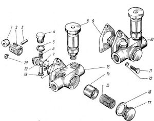
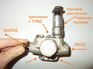
The low pressure fuel pump (LPP) is fixed with three bolts on the high pressure pump (HPP) housing of the YaMZ-236, YaMZ-238 engines. It provides fuel pumping from the tank. Fuel through the coarse filter enters the fuel priming pump, after which it is fed to the fine filter and only then enters the high pressure pump.
Below are photos of TNND in three angles:
While the engine is running, the high pressure fuel pump drives the piston tappet and the fuel priming pump pulls fuel through the system.
Characteristics of YaMZ engines


Director
Alexey Prosvetov
Tel .: (8552) 331-800
Commercial Director
T.V. Kulikova
Tel .: (8552) 331-800, 331-801
Spare parts YaMZ and TRP
Specialist Kadyshev I.V.
Tel .: (8552) 331-800
Spare parts MAZ, URAL, KRAZ, PAAZ
Deputy Director for Development
Kulygin V.V.
Tel .: (8552) 331-800, 331-801
TRP engineer
Bormotayev E.N.
Tel .: (8552) 331-800
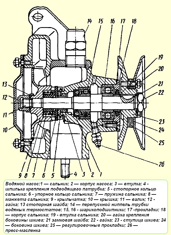
Engine water pump - bladed, centrifugal mud. To prevent liquid from entering the lubricated cavity, a cuff 8 (rice. 64) made of oil-and-oil resistant rubber, which is pressed against the shaft by clips, and with a spring against the textolite thrust ring 6.
Rice. 64. Water pump: 1 - oil seal; 2 - pump casing; 3 - bushing; 4 - stud for fastening the inlet pipe; 5 - an oil seal retaining ring; 6 - a persistent ring of the stuffing box; 7 - stuffing box spring; 8 - oil seal cuff; 9 - impeller; 10 - cover; 11- roller; 12 - nut; 13 - lock washer; 14 - bypass nipple; 15, 16 - ball bearings; 17 - gaskets; 18 -20 stuffing box body; 19 - stuffing box bushing; 20 - nut for fastening the sidewall of the pulley; 21 - lock washer; 22 - nut; 23 - pulley hub; 24 - pulley sidewall; 25 - shims; 26 - grease nipples
A typical malfunction of the water pump (see fig. 64) is the flow of water through the impeller oil seal as a result of the wear of the textolite ring. The wear of the stuffing box is evidenced by the leakage of water from the drain hole on the body of the water pump, which can be eliminated by turning the textolite ring upside down (not worn) to the end of the sleeve pressed into the body, or by replacing the ring with the simultaneous replacement of the rubber cuff.
Blocking the drain hole to eliminate leakage, the stuffing box is not allowed, since water seeping from the pump will get into the bearings and damage them.
Remove the pump from the engine. Unscrew the nuts securing the cover 10 of the housing 2, remove the cover and the gasket. While holding the roller by the pulley from turning, unscrew the cap nut 12 and press the impeller 9 off the pump shaft, remove the retaining ring 5 of the impeller seal and remove all the seal parts from it.
Externally check the technical condition of the stuffing box parts. The textolite ring should not have chips, cracks, or scuff marks on the working surface.
Minor scuffing marks and risks are eliminated by lapping the ring. The stuffing box collar must be elastic, without tears, fit snugly to the shaft and the textolite ring.
Insert the gland spring into the impeller housing, then the rubber gland complete with inner and outer cages, textolite and gland retaining rings.
After installing the retaining ring, the textolite should move freely along the grooves of the impeller when pressed by hand and return to its original position under the action of the spring.
Place the impeller 9 on the pump shaft, secure it with a cap nut and secure it with a washer.
If the bearings or the impeller shaft are replaced, the pump must be completely disassembled.
During repairs, replace felt oil seals with new ones, having previously impregnated them with grease.
When assembling the pump, fill the casing cavity between the ball bearings with Litol-24 or CIATIM-201 grease.
After assembly, the pump roller should rotate freely, without jamming.
Install units in the reverse order of removal.
After installation, fill the system with coolant and check the tightness of the cooling system. Leakage of liquid at the joints of hoses with nozzles, radiator tubes with its tanks, as well as through drainage cocks is not allowed. To ensure tightness, it is allowed to install the water hoses on white.
After installing on water pump motor check the tension of the pump drive belt; when pressing the middle of the branch with a force of 29.4 N (3 kgf), its deflection should be 10-15 mm. To adjust the belt tension, unscrew the nuts securing the front sidewall of the pump pulley and remove the sidewall. Remove one or more (depending on the degree of belt loosening) shims from the studs and, without removing the belt, replace the pulley sidewall.
Install the removed shims on the studs from the outside of the sidewall and screw on the stud nuts without tightening. Wrap the nuts sequentially, in several steps, slightly tightening the one that is between the branches on the side of the crankshaft, turning alive after tightening each nut. In this case, it is imperative to ensure that the belt does not tighten between the sidewalls while it is alive, but extends along their conical surfaces. Check belt tension.
| Video (click to play). |
After installing the drive, grease the shutter cable with CIATIM-201 grease.

