2. From time to time, in the midst of full health, it suddenly does not start. The starter turns, and the motor does not even try to grab. Gasoline pump? After several attempts, it suddenly starts up smoothly and works wonderfully.
2. From time to time, in the midst of full health, it suddenly does not start. The starter turns, and the motor does not even try to grab. Gasoline pump? After several attempts, it suddenly starts up smoothly and works wonderfully.
2. From time to time, in the midst of full health, it suddenly does not start. The starter turns, and the motor does not even try to grab. Gasoline pump? After several attempts, it suddenly starts up smoothly and works wonderfully.
2. From time to time, in the midst of full health, it suddenly does not start. The starter turns, and the motor does not even try to grab. Gasoline pump? After several attempts, it suddenly starts up smoothly and works wonderfully.
1. Before making a harsh decision on a major overhaul, you need to try more loyal measures to identify the causes of the malfunction.
Perhaps the reason for eating the oil is the oil scraper seals, which coke from time to time and our poor fuel, become tough and poorly cope with their function. Since decarbonization helped a little (the caps could soften a little), perhaps it is in the caps that the whole problem is.
2. The reason for the non-factory "just like that" can be hidden in an inexpensive little garbage called a "crankshaft position sensor" (DPKV).
PS: Thoughts on the first point are an exceptional theory.
As for the second point, this is my personal experience.
VIDEO
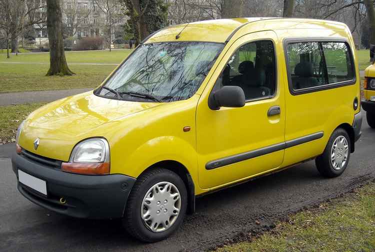
The book contains general information about the device of the Renault Kangoo car since 1997 release, recommendations for maintenance, a description of possible malfunctions of the engine, transmission, chassis, steering and brake systems. Due attention has been paid to the electronic engine management systems.
The technical tips in this manual will help you carry out maintenance and repairs both at the workshop and on your own.
FILLING THE COOLING SYSTEM
The heater radiator valve is missing. The fluid is constantly circulated through the heater radiator, which improves the overall cooling of the engine.
SPECIAL TOOL REQUIRED
Stand for measuring piston protrusion
Magnetic base pointer for angular tightening of bolts
Subframe engine support tool
Pliers for elastic clamps
Belt tension gauge
Mot. 1311 -06 Fuel Line Removal Tool
Engine support tool Torx nozzle for 55
Tension roller nut 5
Crankshaft pulley bolt 2 + 115 ° ± 15 °
Bolt of the upper support bracket 6,2
pendulum engine mount
Nut of the upper support bracket 4.4
pendulum engine mount
Place the vehicle on a 2 post lift.
Disconnect the battery. Remove:
- the timing belt (see the procedure described in Chapter 11 "Timing belt").
Drain the cooling system by disconnecting the drain hose on the radiator.
Fit tool Mot. 1159.
Fit the bracket for tool Mot. 1159 to the place where the coolant hose is attached to the cylinder block, then remove the engine support tool.
- front exhaust pipe;
- hoses and connectors of sensors on the thermostat housing;
- nipple (1) with tool Mot. 1311-06;
- the air filter, while disconnecting the connectors of the exhaust gas recirculation solenoid valve and the air temperature sensor (disconnect the fuel lines from the air filter housing;
- fuel supply control cable;
- power wires for the glow plugs;
- connectors for the injector of the 3rd cylinder with a built-in needle lift sensor, as well as a connector for an accelerated idle solenoid valve (5);
- fittings of the fuel supply and return pipelines in (A) and (B).
Disconnect the connector (6) of the diesel filter sensor, disconnect the filter from the bracket and move the lines along with the filter to the side.
Disconnect the quick disconnect couplings as shown in the figure below.
Remove the bracket for the fuel line holders (7).
Loosen the bolts securing the lower timing cover.
- tensioning mechanism for the accessory drive belt;
- cylinder head bolts.
Separate the block head, moving aside the lower part of the upper cover of the timing drive; carry out this operation without turning the head of the block around the vertical axis, as it is centered by two bushings (C).
Use a syringe to remove any remaining oil from the bolt holes in the block head.
This is to ensure correct tightening of the bolts.
Take measures to prevent foreign particles from getting into the oil supply channels of the block head.
Failure to observe this requirement can lead to blockage of the oil supply channels and cause rapid wear of the camshaft.
It is not allowed to clean the welding surfaces of aluminum parts with a sharp-edged tool.
Use Decapjoint to dissolve adhering gasket residue.
Apply the composition to the surface to be cleaned; wait about ten minutes, then remove adhering gasket residue with a wooden spatula.
It is recommended to carry out this operation with gloves.
CHECKING THE FOOT SURFACE
Use a straight edge and a set of feelers to check if the mating surface is deformed.
Maximum permissible non-flatness:
Grinding of the cylinder head mating surfaces is not permitted.
Check for cracks in the cylinder head.
DETERMINATION OF CYLINDER HEAD GASKET THICKNESS
Checking piston protrusion
Remove carbon deposits from the piston crowns.
Rotate the crankshaft in the direction of rotation one turn so that the piston of cylinder # 1 is near TDC.
Place support Mot. 252-01.
Install bracket Mot. 251-01 with indicator for support Mot. 252-01. Bring the indicator leg into contact with the piston crown and determine the TDC of the piston.
NOTE. All measurements should be taken along the longitudinal axis of the engine to eliminate piston tilt errors.
Measure the piston protrusion.
WHEN SELECTING GASKET THICKNESS, BE GUIDED BY THE GREATEST PISTON PROTECTION.
If the maximum engine piston protrusion is:
- less than 0.858 mm, then a gasket having a tongue with two holes should be used;
- from 0.858 mm to 1 mm, use a spacer with a tongue with one hole;
- more than 1 mm, use a spacer with a tongue with stirrups.
Install the previously selected head gasket. The block head is centered with two bushings (C).
Position the pistons approximately halfway through their travel so that the pistons touch the valves while tightening the head bolts.
Center the block head on the bushings.
Lubricate the bottom of the heads and the threads of the bolts with oil.
Tighten the cylinder head bolts (see chapter 07 "Tightening the cylinder head bolts").
Install in the reverse order of removal.
Install the timing belt (refer to the procedure in Chapter 11, Timing Belt).
Fill with coolant and bleed air from the cooling system
1. Remove the clutch, engine flywheel by locking it with tool Mot. 582-01, oil pan with gasket, toothed pulley, timing mechanism and oil pump seal using tool Mot. 1374 (fig. 3.36). With a nut 1 screw the body of the device inside the sealing collar and, turning the screw 2 , press out the cuff.
2. Remove the oil receiver together with the gasket and the oil pump fig. 3.37).
3. Remove the timing belt tensioner and the coolant pump (Fig. 3.38).
4. Remove the caps of the lower connecting rod heads and bushings, the pistons with the connecting rods, the crankshaft main bearing caps and their bushings, the crankshaft, the main bearing shells located in the cylinder block.
5. Place the piston in the V-groove so that the piston pin aligns with the hole in the support (two marks T the center of the hole is indicated on the support, which facilitates alignment) (Fig. 3.39). Press out the pin using the tool E.
6. Piston pins are pressed into the upper connecting rod heads and rotate freely in the piston bosses. The piston pins are installed using the Mot tool. 574-21 (fig. 3.40).
A - Mounting mandrels B - Thrust bushings E - Mandrel S - Support for the piston.
7. Visually check the condition of the connecting rods (twisting and non-parallelism of the axes of the heads), the adherence of the connecting rod caps to the connecting rod rods (if necessary, remove the burrs with a grinding bar). To heat the connecting rods, use a 1500 W heating plate (fig. 3.41). Place the upper connecting rod heads on the hot plate. Make sure that the connecting rod heads fit snugly against the plate surface. To control the temperature, place on each upper connecting rod at a point "a" a piece of tin solder with a melting point of about 250 ° C. Heat the upper connecting rod heads until the pieces of solder melt.
8. Make sure the gudgeon pins slide freely in the new piston bore. Use a centering sleeve to install the piston pins C17 and mounting mandrel A17 (fig. 3.42). Put on the piston pin E on the mounting mandrel A then screw on the centering sleeve WITH against the mounting bar, and then unscrew it a quarter turn.
9. An arrow is stamped on the piston head, which after assembly should be directed to the flywheel (Fig. 3.43). The direction of installation of the connecting rod is indicated by the protrusion 1 , which should be on the side of the oil dipstick.
10. Install the bushing B17 onto the support, put the piston on it together with the pin, securing the piston with the support spring stopper (the arrow should be directed upwards).
16. All connecting rod lower end bushings are the same. The crankshaft main bearing shells have holes for lubrication both on the cylinder head side and on the bearing cap side. The middle bearing shell is a thrust bearing and determines the axial clearance of the crankshaft.
21. Install the pistons and connecting rods into the cylinders using a mandrel to compress the piston rings (Fig. 3.46).
22. Install the connecting rod bearing caps so that the arrow 1 was facing the flywheel (Fig. 3.47).
24. Apply a roller to the mating surface of the coolant pump 1 sealant Rhodorsea l5661 and install the pump in place (Fig. 3.48).
25. At each assembly, a new sealing ring of the discharge pipe should be installed (Fig. 3.49).
26. Apply a roller 5 of Rhodorseal5661 sealant around the entire perimeter of the mating surface of the oil pump (Fig. 3.50).
27. Install the oil pump on the cylinder block and tighten the mounting bolts to a torque of 9 Nm, a new sealing lip on the crankshaft, taking care not to damage it when passing through the journal on which the timing gear is installed.
29. Apply a bead of Rhodorsea5661 sealant around the entire perimeter of the mating surface from the flywheel side (Fig. 3.52).
30. Tighten the cover bolts with a torque of 9 Nm.
32. Install the oil receiver, having previously replaced its sealing ring (Fig. 3.54).
33. Clean the mating surfaces of the cylinder block and oil pan. Install the oil pan and tighten the mounting bolts to 10 Nm.
36. Wait three minutes for the gasket to stabilize.
39. Reinstall the timing belt, aligning the belt marks with the marks of the crankshaft and camshaft toothed pulleys. 1 fixtures Мt.1386 and tighten the crankshaft pulley mounting bolt: · a - install the device Мt. 1273 and using the tool Mot. 1135-01 turn the tension roller counterclockwise until the display shows the value of 20 SEEM units (to turn on the device, turn the knurled knob of the sensor until the ratchet is triggered three times) (Fig. 3.57).
Tighten the tension roller belt nut. Turn the engine crankshaft at least two turns (under no circumstances turn the crankshaft in the opposite direction). Place the crankshaft at top dead center and remove the retainer. Check the correct installation of the crankshaft and camshaft toothed pulleys of the timing mechanism. Loosen the tensioner roller nut and using the tool Mot. 1135-01 Rotate the roller counterclockwise until both holes are horizontal. Tighten the tension roller nut; · b - turn the engine crankshaft at least two turns (under no circumstances turn the crankshaft in the opposite direction). Place the crankshaft at top dead center and remove the retainer. Install the tool Mot.1386 on the belt branches between the crankshaft toothed pulleys and the coolant pump, apply a force with a torque of 100 Nm (Fig. 3.58). Install the appliance, Mot. 1273 and read the belt tension, which should be 20 ± 3 SEEM units (setpoint).
41. If this is not the case, re-adjust the belt tension by changing the position of the tension roller using the tool Mot. 1135-01 and repeat the operations. starting from point b. Tighten the nut Attention! Never reinstall a belt that has been removed. Replace the belt if the tension is below the minimum service value (10 SEEM units).
Valve clearance adjustment
Adjust exhaust valve clearances 1 and 3 cylinders (Fig. 3.60). Turn the crankshaft to the second mark. Adjust the valve clearances for the intake valves of cylinders 1 and 3. Turn the crankshaft to the third mark. Adjust exhaust valve clearances 2 and 4 , cylinders. Turn the crankshaft: from the fourth mark. Adjust intake valve clearances 2 and 4 cylinders.
44. Install the cylinder head cover and tighten the bolts to a torque of 11 Nm.
46. Install the exhaust manifold after replacing its gaskets.
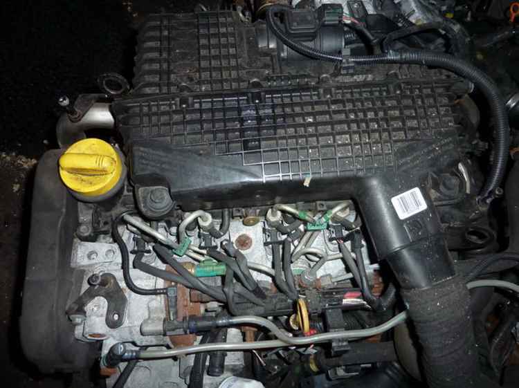
Factory-made Renault passenger cars are equipped with two engine versions - diesel and gasoline. Each ICE has several separate modifications, the power of which varies from 70 to 110 hp. The most common configuration provides for the installation of a standard 1.4-liter petrol engine with an injection system for each cylinder.
The modern engine of a Renault petrol-type car with a total volume of 1400 cubic centimeters has an in-line arrangement of 4 cylinders. Each cylinder is equipped with 2 valves. The angle of inclination of the valve mechanisms is about 17.5 degrees.
This type of installation allows you to reduce the cycle time, as well as significantly increase the overall efficiency of the entire cylinder head, making it no worse than that of a freight transport. The standard engine has a relatively low compression ratio of about 9.5 units per cylinder. On a new motor, deviations from 9.2 to 9.7 units are allowed. This is due to the running-in of rubbing parts, as in any truck.
Overall volume - 1.4 liters (1390 cubic centimeters);Number of valves - 8 pieces, 2 pieces for each cylinder;Gasoline type - AI-92, AI-95;Maximum power of Kangu with a given internal combustion engine - 75 h.p. at 5500 rpm;Torque - from 114 N * m;Location of the CPG - in-line;ICE environmental standards - Euro-4;Mixed flow - 7.6 liters;Vehicle acceleration time - 13.6 sec. up to 100 km / h;Assembled motor weight - 117 kg.The gasoline engine has an overhead valve train. The internal combustion engine develops maximum torque at 2760 rpm. This version is equipped with a fuel injection system, which is controlled by a built-in electronic unit manufactured by Renault.
VIDEO
Thanks to the upgraded version of the processor, which differs from the old 1.3, the car has an increased range and load capacity. On one tank, a car with 1.4 is capable of driving on a combined cycle up to 625 kilometers. With the installed 5-speed manual gearbox, the internal combustion engine accelerates the Kangu model to 154 km / h. In this case, acceleration to a hundred is carried out in 13.6 seconds. A subcompact engine, like a commercial vehicle, often requires a good spin.
Renault 1400cc injection engine cm is the most successful version, which, as standard, is capable of running on popular brands of fuel (AI-92 and AI-95 gasoline). The piston group supports octane numbers up to AI-98, however, in some cases, special additives may be required.
The internal combustion engine on Renault in this configuration is capable of serving up to 300,000 kilometers without carrying out technical repairs.
The guaranteed service life of the unit may vary depending on the specific conditions of use.
The manufacturing plant is prohibited from using fuel with a grade lower than indicated in the accompanying literature. In addition, ICE 1.4 is capable of supporting the operation of the hydraulic booster, air conditioner or an additional pair of headlights.
For normal operation, the Renault injection-type motor is filled with oil with a viscosity of 5w40 and 5w50 (synthetics). The volume can vary between 4-4.2 liters. The manufacturer recommends replacing the filling fluids every 10-15 thousand kilometers, and the filter every 5 thousand. When replacing, take into account the operating conditions of the car engine.
Popular 1400cc gasoline engine cm installed on Renault Kangoo models is reliable and unpretentious in everyday use. During the ride, high economic and dynamic performance is noted, which allows the Kangu version car to move confidently both in the city and on the suburban highway. Volume 1.4 has an average total consumption of about 7 liters per hundred kilometers at a speed of about 60-80 km / h.
availability of spare parts for the engine;
motor 1.4 easy to repair and maintain;
good economy in urban mode;
high torque at low rpm;
low cost of spare parts and consumables.
Kanggu motors are additionally equipped with electronic fuel and air flow controllers, which help the injection system to more accurately navigate to ensure stable operation. Despite some advantages, the 1.4-liter ICE is rather weak in terms of towing trailed devices. Although the overall load capacity does not particularly suffer from this.
Also, this version of the engine has a fairly low cruising speed. It often needs to be cranked up to high revs to provide good dynamics when climbing or maintaining a stable speed on the track.
In most cases, these problems can be easily solved by changing the firmware block to a more modified one. If necessary, specialists replace the piston group from 1.4 to an enlarged one.
In general, this unit is not demanding to maintain, and the cost of its spare parts is at an acceptable level.
Repair of the Renault Kanggu engine can be major, or it can be partial. The type of repair is determined only after diagnostics by a minder. Partial overhaul of the Renault Kangoo engine may include replacing the GBK gasket, replacing valve stem seals, replacing valves. Partial repairs usually do not include removing the engine block, boring, grinding, liner, etc.
You should not make the decision to repair the Renault Kangu engine on your own. People often come to the service who say - “my neighbor told me that I need to change the cylinder head gasket and everything will go away”. Of course, we can listen to the client and go to a meeting, but if this does not help in solving the problem, all responsibility will fall on the client, and not on the service minder who diagnoses and is responsible for him.
Service station on Grazhdanka - 603-55-05, from 10 to 20, no days off. Service station in Kupchino - 245-33-15, from 10 to 20, no days off. STO on Courage , 748-30-20, from 10 to 20, no days off.
WhatAapp / Viber: 8-911-766-42-33
When to repair the engine: - increased consumption of engine oil in the internal combustion engine;
Warranty for work - 6 months no mileage limit.
Engine diagnostics during repair with us is free!
The final cost of an engine repair depends on many factors. Often, people disassemble the engine themselves, trying to make engine repairs with their own hands. When it comes to the understanding that they cannot assemble it themselves, they bring us a disassembled engine. When you call the service station, please specify the current condition of the engine and you will be told the exact cost of its repair.
If the car is not in motion, we can send a tow truck.
SPECIAL TOOL REQUIRED
Stand for measuring piston protrusion
Magnetic base pointer for angular tightening of bolts
Subframe engine support tool
Pliers for elastic clamps
Belt tension gauge
Mot. 1311 -06 Fuel Line Removal Tool
Engine support tool Torx nozzle for 55
Tension roller nut 5
Crankshaft pulley bolt 2 + 115 ° ± 15 °
Bolt of the upper support bracket 6,2
pendulum engine mount
Nut of the upper support bracket 4.4
pendulum engine mount
Place the vehicle on a 2 post lift.
Disconnect the battery. Remove:
- the timing belt (see the procedure described in Chapter 11 "Timing belt").
Drain the cooling system by disconnecting the drain hose on the radiator.
Fit tool Mot. 1159.
Fit the bracket for tool Mot. 1159 to the place where the coolant hose is attached to the cylinder block, then remove the engine support tool.
- front exhaust pipe;
- hoses and connectors of sensors on the thermostat housing;
- nipple (1) with tool Mot. 1311-06;
- the air filter, while disconnecting the connectors of the exhaust gas recirculation solenoid valve and the air temperature sensor (disconnect the fuel lines from the air filter housing;
- fuel supply control cable;
- power wires for the glow plugs;
- connectors for the injector of the 3rd cylinder with a built-in needle lift sensor, as well as a connector for an accelerated idle solenoid valve (5);
- fittings of the fuel supply and return pipelines in (A) and (B).
Disconnect the connector (6) of the diesel filter sensor, disconnect the filter from the bracket and move the lines along with the filter to the side.
Disconnect the quick disconnect couplings as shown in the figure below.
Remove the bracket for the fuel line holders (7).
Loosen the bolts securing the lower timing cover.
- tensioning mechanism for the accessory drive belt;
- cylinder head bolts.
Separate the block head, moving aside the lower part of the upper cover of the timing drive; carry out this operation without turning the head of the block around the vertical axis, as it is centered by two bushings (C).
Use a syringe to remove any remaining oil from the bolt holes in the block head.
This is to ensure correct tightening of the bolts.
Take measures to prevent foreign particles from getting into the oil supply channels of the block head.
Failure to observe this requirement can lead to blockage of the oil supply channels and cause rapid wear of the camshaft.
It is not allowed to clean the welding surfaces of aluminum parts with a sharp-edged tool.
Use Decapjoint to dissolve adhering gasket residue.
Apply the composition to the surface to be cleaned; wait about ten minutes, then remove adhering gasket residue with a wooden spatula.
It is recommended to carry out this operation with gloves.
CHECKING THE FOOT SURFACE
Use a straight edge and a set of feelers to check if the mating surface is deformed.
Maximum permissible non-flatness:
Grinding of the cylinder head mating surfaces is not permitted.
Check for cracks in the cylinder head.
DETERMINATION OF CYLINDER HEAD GASKET THICKNESS
Checking piston protrusion
Remove carbon deposits from the piston crowns.
Rotate the crankshaft in the direction of rotation one turn so that the piston of cylinder # 1 is near TDC.
Place support Mot. 252-01.
Install bracket Mot. 251-01 with indicator for support Mot. 252-01. Bring the indicator leg into contact with the piston crown and determine the TDC of the piston.
NOTE. All measurements should be taken along the longitudinal axis of the engine to eliminate piston tilt errors.
Measure the piston protrusion.
WHEN SELECTING GASKET THICKNESS, BE GUIDED BY THE GREATEST PISTON PROTECTION.
If the maximum engine piston protrusion is:
- less than 0.858 mm, then a gasket having a tongue with two holes should be used;
- from 0.858 mm to 1 mm, use a spacer with a tongue with one hole;
- more than 1 mm, use a spacer with a tongue with stirrups.
Install the previously selected head gasket. The block head is centered with two bushings (C).
Position the pistons approximately halfway through their travel so that the pistons touch the valves while tightening the head bolts.
Center the block head on the bushings.
Lubricate the bottom of the heads and the threads of the bolts with oil.
Tighten the cylinder head bolts (see chapter 07 "Tightening the cylinder head bolts").
Install in the reverse order of removal.
Install the timing belt (refer to the procedure in Chapter 11, Timing Belt).
Fill with coolant and bleed air from the cooling system
We put the car on a jack and unscrew the right front wheel. Let's remove the wheel arch liners and the plastic protection behind which the crankshaft pulley hides.
The location of the pulley is generally convenient. It is not necessary to remove the upper engine mount to lower it a little.
To begin with, we loosen the auxiliary equipment belt - release the upper and lower generator mounting nuts and loosen the belt tension with the adjusting bolt.
The next step is to fix the crankshaft. There are several ways to fix the crankshaft.The first method is through a hole on the engine block designed to fix the crankshaft in a position that corresponds to the piston top dead center. The hole is located next to the oil level dipstick. Using the E14 head, unscrew the bolt that closes the hole and, turning the axle shaft of the right wheel, we look for a metal rod with a diameter of 8 mm, the hole on the crankshaft.
The second way is a little simpler. We fix the flywheel through the hole in the engine block.
We turn on the fifth gear and, scrolling the right semiaxis, we are looking for a hole in the flywheel into which we install the retainer.
Having installed the retainer in the flywheel, we rip off the crankshaft pulley mounting bolt. The bolt fits well, it was unscrewed with a homemade knob made from a crank. One knob was bent, but a light pneumatic wrench could not be unscrewed.
The pulley fits snugly into the pinion, so you may have to tinker a little to remove it.
Video (click to play).
It is noticeable to the naked eye that the pulley must be replaced. The damper has already broken and the outer part of the pulley began to peel off and grind the plastic protection.