In detail: do-it-yourself repair of the prf 750 baler baler from a real master for the site my.housecope.com.
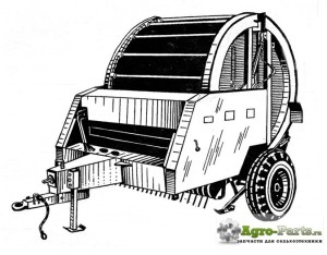
The round baler PRF is designed for picking up hay, grass, as well as straw and subsequent pressing of raw materials into rolls with simultaneous winding with twine.
The baler is designed for use in areas of lowland farming. The baler is aggregated with tractors of traction class 1.4-2.0 with PTO, hydraulic system, electrical equipment outputs.
Depending on the configuration, the balers are produced in the following versions:
- PRF-180 - round baler;
- PRF-180A - round baler with automatic control system.
The PRF-180 baler is a modernized design of the PRF-750 round baler. A distinctive feature of the balers is the modified design of the pressing mechanism, the safety clutch of the pick-up mechanism and the main clutch, the tensioner of the pressing mechanism shut-off mechanism, the front, replacement of the support skis of the pick-up with support wheels, the use of the 10.00-16 Bel PT-5 tire in the running system.
The main components of the baler are:
- lobovina PR-1.8 01.00.000 (item 1) (fig. 1),
- pick-up PR 07.000 (item 2),
- wheel travel chamber base PR15.00.000 (item 3),
- bale chamber (item 4),
- consisting of front and rear chambers, pressing mechanism PR 07.000 (item 8),
- cardan transmission (pos. 6),
- hydraulic system (item 7) and
- electrical equipment (item 8).
1 - lobovina PR-1.8 01.00.000 , 2 - pick-up PR 07.000, 3 - chamber base, 4 - pressing chamber, 5 - pressing mechanism PR 07.000, 6 - cardan gear, 7 - hydraulic system, 8 - electrical equipment.
| Video (click to play). |
The baler works as follows: when moving forward in the unit with a tractor, the mass from the swath is picked up by the spring teeth of the baler PR 07.000 and is fed into the bale chamber, where the lower rollers and rolling pins of the pressing mechanism PR 26.00.000 twists into a roll. With the help of the clamping grid, the pressed mass is pre-compacted. When the preset compaction density in the bale being formed is reached, a signal is sent from the drum to the tractor driver to feed the twine into the baling chamber. Bale wrapping and twine trimming take place automatically when the machine is stopped. After wrapping the bale with twine, using hydraulic cylinders PR 22.00.000-03, the bale chamber opens and due to the rotation of the lower rollers, the bale is unloaded to the ground. After closing the bale chamber, the process is repeated.
1 - pick-up PR 07.000; 2 - clamping lattice; 3 - upper drum PR 02.030A; 4 - casing; 5 - pressing mechanism PR 26.00.000; 6 - bottom rollers; 7 - hydraulic cylinder PR 22.00.000-03(3-50x28-320)
Lobovina (Fig. 4.) is an integral part of the baler, inside of which there is a drive, consisting of a power receiving shaft PR 01.070 A (item 1), safety clutch PRP 05.00.020 (item 2), bevel gearbox KTF 03.000-01 (item 3), shaft with half couplings PR 01.110A (item 4), the drive shaft of the pressing mechanism, the drive shaft of the rollers PR01.01.000 (item 8). A traction loop (item 9) is welded to the front of the forehead for coupling with a tractor. A box for twine with a compartment for storing tools and a wrapping (knitting) apparatus PR 13.000 are also fixed on the forehead. The cam clutch (item 4) disables the drive of the pressing mechanism before opening the rear chamber by means of a cable traction (item 7) connected to the lever of the hydraulic cylinder. After closing the chamber, the coupling is returned to its original state by means of a spring (item 5).
Camera base PR 15.00.000 (Fig. 6) is a support for installing the bale chamber and wheel travel and consists of the following parts - axles with left and right cheeks, on which the front PR 05.140A and rear PR05.050A rollers. At the ends of the axle, pins and wheels are inserted and bolted. At the bottom of the base, next to the rollers, there are two casings PR05.00.340 and PR 05.00.350... On the casing PR 05.00.350 a belt is installed to close the gap between the rear roller and the bars of the pressing mechanism.
The baling chamber of the baler is used to form a bale and consists of the front PR 02.00.000 (Fig. 7) and the rear PR 03.00.000 chambers. An upper drum is installed on the front chamber PR 02.030A , having a mechanism for regulating the density of pressing and a drive shaft of the pressing mechanism. The rear chamber is pivotally connected to the front one, opens and closes with the help of hydraulic cylinders PR22.00.000-03mounted on levers and held closed by hooks PR 02.210A... At the moment of opening the rear chamber, the hydraulic cylinders turn the levers and open the hooks with rods. After the levers have reached the stops, the rear camera begins to rise. On the rear chamber there is a tension axle with driven sprockets of the pressing mechanism. The axle is spring-loaded and moves along the grooves when the pressing mechanism is released.
Pressing mechanisms on PRF-180 balers are installed of two types:
The pressing mechanism is designed to twist the pressed mass into a roll and is made in the form of a closed chain-slat conveyor. Roller supports are installed at the ends of the bar.
Wrapping machine PR 13.000 (Fig. 4D) is intended for wrapping the bale with twine and consists of a twine feed mechanism, carriage, leashes, stop, brake, knife and carriage drive mechanism. The carriage drive mechanism is connected to the pulley through a closed chain loop and gear train. The rotation of the pulley is carried out by twine, which from the bobbins, passing through the brake, bending around the pulley, through the feed mechanism enters the baling chamber, where, being captured by the roll, it is wound on it and moves the carriage. When the carriage moves, the twine is captured by the leash and moves along the roll from left to right (along the machine), when the extreme right position is reached, the twine is captured by a stationary leash, and the carriage, moving to the left until it stops, cuts the twine with a knife. The capture of the twine by the bale on the balers is carried out as follows:
- on the PRF-180 - when the specified bale density is reached and a signal is given, the tractor driver, pulling the cord tied to the ring, rotates the feed mechanism rollers, thereby pulling the twine until it is captured by the bale;
- on the PRF-180A - when the preset bale density is reached and the “DENSITY” light indication on the display panel installed in the tractor cab is switched on, the electric motor of the feeder drive is automatically switched on, thereby feeding the twine until it is captured by the bale. Manual control of the electric motor is possible, for which the toggle switch on the display panel must be set to the "MANUAL" position, and to start the electric motor, press the "Feed" button. After the twine is captured by the roll, the wrapping cycle is carried out automatically, and at the end of the twine, falling on the knife, is cut off.
The beltless round baler PR-F-750 is designed for picking up hay rolls of natural and sown grasses or straw, pressing the mass into cylindrical bales - rolls with subsequent twine wrapping. Type semitrailer. It is aggregated with tractors of classes 1.4 and 2. Serviced by a tractor driver. Recommended for use in areas of flat land use.
PR-F-750 in comparison with the PRP-1.6 baler has better performance indicators, 2 times less weight loss, especially of small fractions, due to this, the carotene content in hay increases. The bales formed with the help of the pick-up have a regular geometric shape with a low-density core, which allows them to be dried in the field or by active ventilation. Consumption of binding material is 1.8 times less compared to the basic machine. The use of the machine eliminates the need for zigzag movements when collecting a roll, requires a minimum number of adjustments, as a result, productivity is much higher, and labor costs are 24.2% less than when using PRP-1.6.
Technical and technological maintenance of the PR-F-750 baler is safer and more convenient than the PRP-1.6 baler.
The annual economic effect is 2163 rubles.
The baler consists of the following main parts:
- cardan transmission, used to transfer torque from the tractor PTO to the gearbox;
- a drum-type pick-up for swath pick-up;
- bale chamber, consisting of front and rear (opening) parts;
- beltless pressing conveyor for roll forming;
- bale wrapper;
- signaling about reaching the set compaction density;
- wheel travel;
- lighting equipment.
The cardan drive and the pick-up are unified with the PRP-1.6 machine.
Pick-up includes a rotor with five rakes, on which spring fingers are fixed for picking up the mass from the roll, the left shield, clamps attached to the brackets, and the right shield with a treadmill.
Bale chamber consists of a front part, on which an upper roller with a compaction density control mechanism is installed (Fig. 1), and a rear one.
The rear is pivotally connected to the front and lifted by hydraulic cylinders. At the rear of the pressure chamber, the tensioning device of the pressing conveyor is mounted. During operation, in order to prevent spontaneous opening, the rear part is fixed with latches, which are actuated by hydraulic cylinders.
Pressing conveyor designed to form a roll. Consists of two pulling chains with special links, which include cross-rolling pins. At both ends of the rolling pins, rollers are installed that move along the tracks of the baling chamber (Fig. 2).
Bale wrapper (Fig. 3.) is a cross beam, in which an endless contour of a chain is mounted that moves the carriage. The twine is fed into the bale chamber together with the mass picked up by the pick-up using a feeder consisting of two rollers. The guide bar grips the twine and, moving along the bale, wraps it around. The wrapping machine has four modes of operation with different winding pitches.
Signaling is a remote control, the signal to which comes from the density regulator. When the set density is reached, the signal for the end of pressing is given. The alarm works in both sound and light modes. Switching is done with a toggle switch on the remote control.
Wheel travel - welded structure in the form of a beam with semi-axles on which the wheels are installed, and two brackets with lower rollers.
Lighting equipment is a device mounted on special brackets, clearance and swing lights.
The baler leaves the factory packed in accordance with the shipping documents and must be assembled in accordance with the technical description.
When preparing the baler for operation, it is necessary to perform the following work: bring the tire pressure to normal; remove safety grease from assembly units and parts; adjust the tensioning devices of the pressing mechanism and the pick-up sign; tension sleeve roller chains; connect the propeller shaft joint to the end of the shaft, fasten the propeller shaft cover with bolts; fill with twine, for which place four bobbins in the box, tying the inner ends of the previous bobbins with the outer subsequent ones. Tie the cord supplied with the baler to the ring.
When preparing to operate the tractor, it is necessary to check the serviceability of the hydraulic system; connect to the side outlet of the tractor hydraulic system through the union (Fig. 4) a sleeve with a length of 2010 mm, to its end - the left breakaway coupling housing; set the distance of the PTO of the tractor to the axis of the trailing fork hole equal to 509 mm (dimension B), from the PTO to the cross member 200.220 mm (dimension B), from the cross member to the ground 430 mm (Fig. 5).
Using the linkage mechanism, raise the tractor's frame, fix the support in the upper position, lower the frame to its original position (dimension B).
When connecting the baler, back up the tractor so that the bottom of the machine is on the same axis with the tractor PTO shaft.
Connect the shackle of the lower part with the tractor's trailer fork, and the propeller shaft with the PTO shaft, fixing the hinge fork with a bolt. Secure the PTO shaft cover on the tractor linkage brace with the chain circlip.
Install the safety cable by throwing it over the crossbar of the tractor's hitch and fix it in the hole in the eyelet on the bottom bracket.
Connect the oil lines for opening the rear wall to the rear outlets of the tractor hydraulic system, the oil line for lifting the pick-up - to the sleeve from the side outlet.
Connect the cable plug (Fig. 6) to the tractor socket, the control panel plug - to the cable socket, 2 - control panel plug - to the socket for the portable lamp in the tractor, the control lamp on the control panel should light up. Check if the 2 - pin plug is connected correctly. To do this, set the alarm switch on the control panel to the “light” position. Press the density indicator button (Fig. 7) and watch the density indicator light on on the control panel. If the density indicator light does not turn on, you need to change the polarity of the 2 - pin plug connection. Fix the control panel in the tractor cab. After work, disconnect the 2 - pin plug of the remote control from the socket.
Release the left wheel by turning the handle forward (to position B) (fig. 8).
After connecting the baler to the tractor, the unit is adjusted (adjusting indicators are given in Appendix 1). This requires:
- install the unit on a level surface;
- adjust the safety clutch of the drive, pick-up and drive of the pressing mechanism, do not allow the springs to compress until the coils touch;
- use the stop to set the distance from the ends of the spring teeth of the pick-up to the surface of a flat area, with the horizontal position of the bottom it should be 10.20 mm, moving the stop, the distance can be increased if necessary;
- depending on the mass to be pressed, adjust the density indicator by compressing the spring;
- adjust the step of wrapping the bale, which depends on the diameter of the pulley, with the largest diameter, the wrapping step is minimal, with the smallest - the maximum;
- set the extreme position of the twine wrapping on the roll by rearranging the limiters;
- adjust the parking brake drive mechanism;
- carry out maintenance before running in;
- run in under load;
- closely monitor the condition of all fasteners, movable and fixed joints, welds, oil leaks in the hydraulic system.
When the machine moves over the roll, the spring fingers of the pick-up pick up the mass and feed it into the bale chamber, in which the mass is brought into rotation by means of the rollers and the pressing mechanism (Fig. 9). As the mass arrives, its compaction occurs, as a result of which the peripheral layers are denser than the core.
As the mass arrives further, its density in the chamber increases, the signal is transmitted through the upper drum to the alarm device, which turns on when the specified density is reached.
When feeding the crop into the bale chamber, the upper roller prevents clogging of the inlet opening. After activating the alarm, the tractor driver activates the wrapping machine.
The bale is wrapped with twine when the machine is stopped.
The bales should be wrapped with synthetic twine for the baler according to TU-6-06-S128-82. The characteristics of the recommended strapping material are presented in Table 1.
After wrapping the bale, the tractor driver opens the rear part of the chamber using a hydraulic cylinder, thus disengaging the cam clutch on the drive of the pressing conveyor.
Later, when the drive is turned on, due to the rotation of the lower rollers, the bale is unloaded from the bale chamber onto the ground. After closing the rear part of the chamber, the unit again moves along the roll, and the process of forming the roll is repeated.
To obtain a high-quality roll, its good preservation, it is necessary that the moisture content of the pressing mass is within 20.23%.
To reduce the loss of the material to be pressed during harvesting of legumes, as well as to form a high-quality bale on fine dry straw, it is recommended that pressing be carried out in the morning and evening.
For high-quality and reliable operation of the baler, the width of the selected swath should be no more than 1.4 m.
To carry out work on the procurement of fodder, in agrotechnical terms with the highest yield per unit area with minimal labor and funds per unit of production, it is necessary to ensure a high organization of mechanized labor.
The basis of the feed production workshop should be a complex mechanized squad or a specialized team with an approximate set of equipment presented in table. 2.
The PR-F-750 baler is operated in conjunction with loading and unloading equipment. For loading the bales formed by the baler, loaders PF-0.5 and PKU-0.8 with the PT-F-500 device are used. The most expedient technological scheme is one in which two devices are involved: one with a PKU-0.8 loader for picking up and loading, the second with a PF-0.5 loader for stacking. The unit with the captured bale approaches the vehicle, and loading is carried out both from the side and from the side of the tailgate (Fig. 10).
On a 2PTS-6 trolley with folded and tied side boards, it is possible to load without lashing (for transportation within the field) 5. 7 rolls after PR-F-750. At the places where rolls are laid for long-term storage, it is advisable to use a device in a unit with a PF-0.5 loader, which makes it possible to form higher stacks than PKU-0.8 (Fig. 11).
The relatively high resistance of rolls to atmospheric precipitation makes it possible to store them in the open air with predominantly stacking in one row in a dry, elevated place. In Western European countries, rolls are stacked in stacks and covered with foil or loose straw.
The service life, technical condition and constant readiness of the baler for work depend on timely and high-quality daily and periodic maintenance (every 60 hours of operation).
Maintenance is carried out using a tool from the tractor kit or stationary and mobile maintenance units.During daily maintenance, before starting to work with the baler, it is necessary to clean the front and the shaft of the pressing mechanism from dirt, plant residues.
By external inspection, check the completeness of the baler, the fastening of the covers, critical bolted joints, the absence of oil leaks in the joints, the tension of the chains, if necessary, align or replace the teeth of the pick-up.
When carrying out periodic maintenance, in addition to daily maintenance, it is necessary to check and bring the pressure in the tires of the baler's wheels to normal (should be 0.35 MPa or 3.5 kg / cm); check chain tension; correct adjustment of the engagement clutch, lubricate the conveyor engagement clutch.
After periodic maintenance, the detected faults are eliminated. Possible malfunctions and methods of their elimination are given in Appendix 2.
These safety measures do not relieve the management of the farms from the obligation to take additional measures if necessary.
Once again I am repairing the baler and something tells me that it will not be the last).
Hello Zhen. ran into a little problem. how to put a new transporter? the old one was pulled out before me and the new heavy one and where is it better to start on the asterisks? I can not find information anywhere. tal there is still 1 partner)))) like foxes we walk around the jug))))


thank you)))) stuck in 8 people)))) first threw it on the open press held under the drive star and then with a gas key twisted the drive sprocket from the top pulled and held the conveyor 1 person .. inside 3 people lifted the conveyor along the grooves (there were mats .) well hodo poorly in 30 minutes they stuck it there))) (praise the gods.)


Hello, start from the back inside under the open lid, as in my video, From the top to the slot, a thin cable or a towel is better, first remove the visors for convenience, well, and then crowbars, edgers, tal, by fart steam,))) ) without a hoist on the street, a tractor was pulled, it is advisable to prepare a couple of chains or a strong meter long rope with hooks at the ends, for quick fixing of the conveyor so that it does not accidentally roll out back after a couple of hours of fucking)))))))

Brother, repair it soon, he needs to roll it while the weather is on))

I noticed one important point - there are no scrubbers on the leading sprockets of the conveyor, as a result, hay is wound up that can turn out anything. Because of this, the conveyor “flew off” and “fitted” the scrubbers into a tight one to the sprockets and did not recognize my old press.


hi friend can advise me 180 prf started to tear the twine, even at two, it still tears it reaches about the middle and breaks took off the winding mechanism there everything is normal to spin easily nothing cries


thanks for the answer, I understood you, but I did brew and grind the leash with a grinder, I got the idea today to open the camera and pull the twine until a full cycle or break with my hands, I think I will feel and the press does not rumble


hello, look there the bar on the leash mechanism seems to be there, this bar was soaked in the groove and it became sharp, it also vomited at a certain moment, I remember that I welded this bar, it seemed to help


Hello. Tell me (if you know) what is the difference between pr-f-750 and pr-180, and which one is better to take?


oh well, what a smart, fool, fool))))) just all my life with technology, I'm glad that I could help at least with something


Many thanks! It was nice to talk to an intelligent person.


in my opinion, you need to pay special attention to the condition of the conveyor, namely to the rollers and the treadmill, if the track is already welded on and the conveyor is stretched to the limit (there is no place to pull), then everything else will also be with great wear, the conveyor is the most expensive pleasure in press, the rest can be more or less treated, it is also advisable to look at the gearbox so that all the safety couplings are in working order, and not welded on dull as is customary with us)) well, that's all


Thank you. I don’t pull on the new one. If so, what should you look at first of all?


hello, as far as I know, they only have different names, but these are almost the same PR difference, most likely not significant for the little things to take, of course, it is better to take any of them, but a new one, if it’s natural that it’s newer))

Baler operating instructions is always supplied with this agricultural machine. Thanks to such a document, any buyer who was not previously familiar with the technical features of the purchased model can learn all the nuances and subtleties of the correct use of the purchased equipment. However, many farmers often neglect the instructions set out in the manual, due to which the life of the device is significantly reduced.
The fact is that baler manual contains not only information about dimensions. It also indicates all the components of the mechanism, their design, purpose and principle of operation. Moreover, the document contains diagrams of the main units, methods of adjusting individual organs, methods of setting them up. Moreover, some manuals provide information on how to prepare the device for use or repair it in the event of a breakdown.
Of course, for experienced mechanics or engineers, this information may not carry any meaningful information, since they are already quite well versed in the technical component. Nevertheless, sometimes breakdowns occur, the cause of which is not so easy to determine. Actually, it is in this case that it can help just baler operating instructions, where the main causes of breakdowns and methods for their prompt elimination are given, for example:
Instructions for prompt repair of the baler Kyrgyzstan
Flywheel hairpin is often sheared
Sharpen knives or replace them with new ones
The counter and the piston knife are dull
Clutch pawl spring is sticking
Running in the knitting machine for 10-15 minutes with periodic switching on after 20-30 seconds or replacing the coupling with a new one
The knotter clutch does not work
The wrapping twine breaks
Check the spring tension of the twine brake and loosen if necessary
The hook has not caught the twine
Check the position and operation of the clamps
In principle, all new modern pick-up models, especially those that are still subject to warranty, can be serviced in specialized service centers. But in most cases, many Russian farms use old devices that were produced in the last century in the Soviet Union, such as the same baler Kyrgyzstan. Naturally, almost all of the samples for sale are not complete with manuals.
It would seem, well, what's wrong with that? If you want, you can always find baler manual in the Internet. But unfortunately, almost all of the versions that are presented on the web, at best, are scanned pages of rather poor quality. At worst, you run the risk of catching malware. In turn, we slightly modified these documents for better readability, since it was inconvenient to look at the inverted diagrams.
By the way, baler operating instructions, especially for the brand "Kyrgyzstan", will increase the service life of the device, if you resort to the rules set out in it. How is this possible? It's actually pretty simple. Manufacturers have indicated in the documentation several extremely undesirable situations that are typical when using this unit. Actually, the task of the owner of the equipment is only to comply with such norms, for example:
- It is forbidden to use a handicraft trailed fork
- It is forbidden to carry out work without fixing the covers of the main driveline
- It is forbidden to use shear pins made of other material.
- It is forbidden to install shear pins of greater strength
Failure to comply with these or other rules that provide baler manual, may cause an emergency. And if the situation leads to rapid wear or breakdown of some structural unit, this is still half the trouble, since you can find the necessary spare part and make a replacement. True, in this case downtime and financial costs cannot be avoided. But a situation dangerous to human life may well arise.
One of the many important uses that any baler operating instructions, is information about the technical characteristics in a specific model of the unit. In particular, with the help of such a document, it is possible to find out what kind of traction device the pick-up should be mated with, and what traction power class is characteristic of it. So, for example, all types of this technique are divided into the following two classifications:
- large units
- mini balers
The difference between them is that large-sized is used, as a rule, on an industrial scale for processing large areas. And the second, in turn, is used to work on small-sized private lands with both walk-behind tractors and tractors of small or medium traction class. Failure to comply with these standards will not allow using all the capabilities of the purchased equipment to the maximum, which will lead to the loss of precious time and resources.
Moreover, baler operating instructions allows you to determine the climatic conditions suitable for it, as well as the features of the terrain and landscape. For example, pick-up Fortschritt K-454 can be used on almost all types of terrain. The only exception is mountainous terrain, the slope of which will be more than 20 ° in relation to the horizon. At the same time, forehead can be used with tractors from 1.4 up to 3 traction class.
At the same time, the PRF baler, namely, the PRF-180, will be used with the MTZ-80, MTZ-82, YuMZ-6 tractors, as well as with the MTZ-1221 and LTZ-155, that is, only with machines or 1.4 or 2 traction classes. It makes no sense to use a traction machine of a heavier class. It also makes no sense to use heavy tractors with high-performance attachments in small areas, as this is not a cost-effective method.
In principle, every farmer knows firsthand how important it is to use all the resources at his disposal, be it a land plot or machinery, as efficiently as possible. However, ignorance of some of the nuances that are mainly prescribed baler operating instructions, can greatly harm the entire process of work. It is for this reason that we advise you to study the documentation after purchasing a supported technology.
Adjustment indicators and possible malfunctions and methods of their elimination for PRF balers
Adjustment indicators of PRF balers:
You can ask questions only after registration. Login or register, please.
Interested in reviews of the PR-145S ROLLED PRESS-SICKER from Bezhetsk. Is it worth taking a press from this plant?
Interested in reviews of the PR-145S ROLLED PRESS-SICKER from Bezhetsk. Is it worth taking a press from this plant?
Hello everyone!
I'll tell you from practice. The chain press is more reliable than the belt press, I myself have been using the PRF-750 chain press for 17 years.
1. To collect hay, it is not required to dry thoroughly, unlike the belt one, since the belt one compresses more tightly than the chain one. During harvesting, we collect hay by touch, sort of like greasy, we determine whether it is ready to be harvested by twisting the dried hay into a bundle, if it smells like hay, not grass, we begin to roll it into rolls without hesitation, even if a little rain is sprinkling. But hay does not lose its qualities for several years and does not burn, even flowers do not lose their color.
2.Unlike the belt pick-up, the chain pick-up is not whimsical, the belts do not break and are the easiest to use.
3. In this case, the 145th goes sideways, unlike the 750th, this adds a plus to it. It is not required to spread the wheelbase of the tractor so that the wheels do not step on the portage.
The only advice: do not try to twist the hay according to the principle "the denser the better", if you overload the bunker, it starts to go at the seams and warps. I think that the mass of a roll on this press should be 220-250 kg (depending on the amount of grass).
Thanks for the detailed answer!
Then the question arose, in the transport position this press also rides on the side of the tractor?
There is still a question, does it badly affect the state of the press only when the shaft is small or when it is very large, can it choke?
In the transport position, it folds like Kyrgyzstan, that is, the carrier breaks and the press follows the trail of the tractor. And at the expense of the "heads" so for the presses it is not a problem when all the spokes on the pick-up are intact, you just raise the tractor hitch higher and the clearance for the passage of hay can be adjusted so that the logs will fly


I personally did not work on it
I saw one on the farm nearby, talked with an engineer, in short, on a new one, they worked out a year and shaved it off, in terms of quality it lags behind the Bobruisk prf 145
but the fact that it goes from the side is not such a big advantage, if the harvest is high and the windrows are in 3 meters, how to press it on it? remove bales from the path or trample a swath with a tractor? even the hooks that fix the back of the bale chamber are welded from parts, and in Bobruisk, one-piece stamped
by the way, in the topics about the press and about hay harvesting equipment, there were reviews about him
the clutch breaks down quickly, rolling pins bend, they are hollow, and so on.
Those topics quickly flipped through, did not notice.
Accordingly, in terms of reliability, the Bobruisk ones are more reliable
. in short, on a new one, they worked out a year and shaved it off, in terms of quality it lags behind the Bobruisk prf 145
but the fact that it goes from the side is not such a big advantage, if the harvest is high and the windrows are in 3 meters, how to press it on it? remove bales from the path or trample a swath with a tractor? ...
I think it's a matter of specialists. I got (bought out) "Kirgistan - 2" from the collective farm, the season was tormented and abandoned, and all I had to do was climb with a barbell, when I gave out 400 bales per hour on "Kirgiz", so we went to watch from the same collective farm 🙂 they didn’t believe everything. And I got PRF-750 already with a skewed bunker and burst at the seams, that's why I mentioned the chain overload. But there you can adjust the sensor and the density of the bale.
Regarding the fact that the move from the side interferes. So in our north, the grass is mostly packed, and when you walk over the wolf of tractors, you pull the hay already with a pallet.
So, probably here you yourself have to choose how the press equipment should go from the side or from the back, depending on the average or main intake of grass
Accordingly, in terms of reliability, the Bobruisk ones are more reliable
unfortunately it turns out that our domestic is lagging behind
do you want to take a new one?
I have prf 145 1993, it differs from prf 145, which have now been modernized and strengthened a lot
by the way, after all, the difference in price between Bezhetsk and Bobruisk is small or you are captivated by the side course of the Bezhetsk, then you don't need to turn your head, just look at your side
Procurement of forage is a responsible business. I don’t want to skip it because of a problem. I have never used the press. Until you figure out what the matter is, it will soak you in the rain.
A press for 60 thousand rubles is sold nearby. killed, they want to write off for scrap. Well, I'll take it, put it in again and it will turn out to be half of the new one))
Bezhetsk was interested in the fact that I myself can come to the plant on a straight line. It should probably be better with spare parts, it seems to me. And then the customs will start to fever and you will not find spare parts)))
And the difference at the moment in price between the Bezhetsk and Bobruisk 11 thousand in favor of the Bezhetsk. But this is not essential.
For the winter, the hay was almost prepared by hand. Today we'll put together a couple of carts. We'll add 2 more carts and the hay harvesting will be finished.
I want to take the press in winter, maybe the price will drop a little, and there will be no queue.
I have never used the press. Until you figure out what the matter is, it will soak you in the rain.
A press for 60 thousand rubles is sold nearby. killed, they want to write off for scrap. Well, I'll take it, put it in again and it will turn out to be half of the new one))
It depends on what to invest, if the gearbox and shafts are finished, then there will be a lot of investments, if welding and cuffs for hydraulic, then maybe you should think? How much does a new one cost?
Damn, the sky brightened up, went to the field. another 250 tons must be delivered. Good luck to all.
He is over 15 years old, there is a problem with the shafts.
In addition, you probably won't find spare parts, a lot has changed during this time.
Now he is with the nth owner, when the last owner bought it, he had to manually pull out the rolls.
Somehow I was asking the price of spare parts, some of them cost 40 tr each
Procurement of forage is a responsible business. I don’t want to skip it because of a problem. I have never used the press. Until you figure out what the matter is, it will soak you in the rain.
A press for 60 thousand rubles is sold nearby. killed, they want to write off for scrap. Well, I'll take it, put it in again and it will turn out to be half of the new one))
Bezhetsk was interested in the fact that I myself can come to the plant on a straight line. It should probably be better with spare parts, it seems to me. And then the customs will start to fever and you will not find spare parts)))
And the difference at the moment in price between the Bezhetsk and Bobruisk 11 thousand in favor of the Bezhetsk. But this is not essential.
For the winter, the hay was almost prepared by hand. Today we'll put together a couple of carts. We'll add 2 more carts and the hay harvesting will be finished.
I want to take the press in winter, maybe the price will drop a little, and there will be no queue.
yes, it's a matter of choice, if the plant is nearby and other circumstances
I don’t want to impose, but I would choose Bobruisk, it is more widespread, there are a lot of them and second-hand, but the Bezhetsk is not visible
and manually harvesting in such heat is very difficult and the hay has time to burn out, in the rolls and this greatly reduces its quality
This year I used a little drag. It made it much easier.
I'll have to go to Bobruiskaya street to see.
Have worked a little like this this season.
except that it was done very obscenely (and this is putting it mildly), more complaints have not arisen yet. Yes, and they worked very little, at the very end of the season he came. And the fact that in the working position rides from the side - you have to twist your neck less, and when you thought of adjusting the mirror, then in general it was a song.
Health to you and your animals!
Bought this year. I don’t know which plant. Nobody dragged such a kfkh. They put a tractor driver who used to work on a belt. In a steel drum, the string pulls the raw bearings. The balls are oozing, deformed and jammed. The tractor driver did not notice and erased the rubber roller. And before that, it turns out, he turned off the signaling of the start of winding. Like got it with false positives. The contacts there are really obscenely made, plus / minus a full centimeter of backlash. You will bring it closer to everything. If you move it away, it may not close. In short, he suffered with the press until the drive cable unwound. (In the middle he stopped knitting and tore the twine). He offered him help, says that everything is OK. Configured.
Now I don’t know what to think. Either the press was unfinished, or the tractor driver had to be driven immediately.
____ The rubberized rollers were leveled with a knife and the season was finalized. Where can you buy these? In the spring, I'll have to mess with him. Make you divine. Maybe I'll work on it if we don't find an experienced tractor driver.

This is how it looked only when equipped.
my eyes are scared, my hands are out of my ass, but I don’t give up ツ
For the period from the end of July to mid-September, a little more than 2,000 rolls were wound.
I took a few photos today:

And here is cocoa.The bearing on the metal twine feed cylinder is wet and seized. The tractor driver did not notice how he gnawed the rubber rollers like an apple. I had to trim the rubber with a knife. Finalized before the end of the season. Now we need to look for these rubber bands.


The roll does not start to wrap up completely from the edge. The twine goes to the other edge, then returns and is cut off at the edge. It turns out that one end of the roll is not well wrapped. Then he starts to shaggy. I wish I could somehow alter it so that I start winding from the middle and finish in the middle.
The photo shows the same Bezhetsk press. I used to sell such people, they seem to work. Or are people silent?
We have two such press in the village. We have one, the second in the municipal unitary enterprise (according to the old state farm). Their chain is thinner than ours. But I worked for two seasons. An intelligent tractor driver immediately figured out what's what. And his press works more or less. Not without breakdowns, but not much swearing. And we had several raw bearings. The balls are deformed. Egg-shaped steel. And in some places it was badly welded. On the move, they put them back in place on the field and welded them on. But the season has worked. Now, I hope, after a small repair, the season will definitely work out. And then we will see.
It will work, and more than one season.
This is the technique of our production - it works while you repair it.
Despite all the shortcomings, this, and any domestic press has one property very convenient for the foreman, agronomist, director of the farm. When I worked as a chief agronomist, I didn’t have to control every now and then whether the unit was working, or Vanka-Lyoshka was sleeping under a bush, blown away by the heat. say online. :


Doctor, take Bobruisk! The first, even though the Bezhetsk, takes up a lot of space on the right, which brings a lot of inconvenience when driving on the roads, when the traffic cops come to cling to the peasants with the pallet clings, when you are driving a wolf, you need to make a smaller swath and nothing will cling to. Bobruisky goes strictly behind the tractor and this is a plus on the road the traffic police have no problems, in the field you will not rest against the already wound rolls. Bobruisk is easier than Bezhetsk, when you see and compare you will understand. The roar creates a chain-laden mechanism when it rolls from one half of the drum to the other, I also cut off the opening half on the canopies, podkrtit on both sides and welded on a new one, it became much quieter. About spare parts and customs everyone drives MTZ tractors and buys nothing. And one more minus of Kyrgyzstan and Bezhetsk is a very large load on the tractor hitch, I will give you an example. Is it easier to drag something heavy from the side or is it better for you? How easier? I took myself a prf-110 from the Bobruisk plant, a new one, it cost 340 thousand rubles. And water the chain-blade chains that will last longer!
Doctor, take Bobruisk! The first, even though the Bezhetsk, takes up a lot of space on the right, which brings a lot of inconvenience when driving on the roads, when the traffic cops come to cling to the peasants with the pallet clings, when you are driving a wolf, you need to make a smaller swath and nothing will cling to. Bobruisky goes strictly behind the tractor and this is a plus on the road the traffic police have no problems, in the field you will not rest against the already wound rolls. Bobruisk is easier than Bezhetsk, when you see and compare you will understand. The roar creates a chain-laden mechanism when it rolls from one half of the drum to the other, I also cut off the opening half on the canopies, podkrtit on both sides and welded on a new one, it became much quieter. About spare parts and customs everyone drives MTZ tractors and buys nothing. And one more minus of Kyrgyzstan and Bezhetsk is a very large load on the tractor hitch, I will give you an example. Is it easier to drag something heavy from the side or is it better for you? How is it easier? I took a prf-110 for myselfThe new Bobruisk plant cost 340 thousand rubles And water the chain-blade chains of some sort will last longer!
| Video (click to play). |
I completely agree that Bobruisk will be better.
Only chains should not be smeared. Dust will settle on them and wear will increase significantly.
About twenty years ago, having come to practice at the farm, he tried to force the machine operator to lubricate the chains on the seeder. Now I will probably never forget that they are smeared only when storing.
The press works only in dry weather and dust when enough.

