In detail: do-it-yourself repair of the t2 set-top box from a real master for the site my.housecope.com.
Since the late 90s of the last century, audio - video technology has evolved greatly. From VCRs and DVD players, CD and MP3 recorders, to omnivorous media players that allowed you to read media files from a USB flash drive. Such devices cost 3-4 thousand in due time.
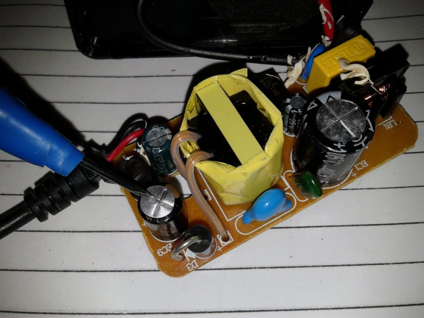
Now every DVB-T2 receiver can do it. The receivers are quite cheap - from 900 rubles, and in addition to reading media files from a flash drive, they allow you to watch television with digital quality for free, albeit only 20 channels. And everything would be fine if the Chinese, in pursuit of cheap devices, did not put low-quality parts there. I have had cases when in a receiver with a built-in power supply, after 2 years of operation, a small electrolytic capacitor had an overestimated ESR.
Shallow electrolytic capacitor
And accordingly, the receiver did not turn on, after measuring the equivalent series resistance ESR with a meter, and replacing the three-ruble capacitor, everything returned to normal and the receiver turned on. But this, as they say, was just lucky. More often, DC-DC converters burn out in receivers. Sometimes, fortunately for the user who decides to repair the set-top box on his own, stabilizers with 3 legs are installed instead, the replacement is not difficult, but sometimes the boards have unreliable five-legged converters, we will analyze this case. There are 3 of them - small microcircuits in the SOT-23-5 package.
Chip Converter - drawing
They give respectively 3.3 volts required to power the RAM microcircuit, 1.8 volts and 1.2 volts required to power the processor.
| Video (click to play). |
Dimensions of converter chip
It is easy to determine where the output of the microcircuit is, even without a datasheet for this microcircuit, the output of the converter is connected by a track with a choke necessary for the operation of the converter. You can familiarize yourself with one of the typical converter circuits by looking at the figure below:
Converter wiring diagram
What if your set-top box refused to turn on, you opened it and, having called, found two or more terminals in a short circuit or low resistance? Such converters, due to the fact that their binding is sometimes individual and incompatible with other types of converters, it is necessary to change them strictly to exactly the same, or in extreme cases to full analogs taken from datasheets.
Converter chip pinout
The wiring diagram, the ratings of the parts, the output current, and of course the output voltage must completely match. I got one of these attachments for repair with a 3.3 volt converter power input punched to the ground. A quick search in the radio stores of our city showed that we have no such microcircuit or complete analogs anywhere else.
Converter to Ali Express Party
And on Aliexpress, they were only in batches of at least 10 pieces, and with expensive paid delivery, which did not suit me. How to be in such a situation? The solution was found and I decided to share it with the readers of this site. Moreover, the output is very low-cost, in terms of the cost of parts in comparison with the purchase of a batch of converters.
Photo converter board
The fact is that for design on arduino and microcontrollers, special small-sized converters, stabilizers are produced in China, immediately with the necessary body kit soldered on the board for their operation. These are AMS1117 stabilizer microcircuits familiar to many electronics engineers.
Stabilizer ICs AMS1117
These microcircuits are produced as adjustable, which is unnecessary for us in this case, and with a fixed voltage at the output, but we are interested in voltages of 1.2, 1.8, 3.3 volts. For all these voltages, ready-made converter shawls are on sale on Aliexpress, based on these stabilizers. How can you distinguish between converter boards, if, for example, you bought them earlier and forgot what voltage they are?
On the case of microcircuits, in addition to the name of the model, stabilizers for a fixed voltage, it is sometimes written the voltage that will be at the output of the converter, that is, the same 1.2, 1.8, 3.3 V we need. How to place these converters in the receiver case? They will not take up much space, I would not think long, MGTF soldered to three of the contacts on the converter board, there are 4 of them: input plus power, output plus power, and two contacts common for input and output ground.
Why we use three contacts out of four I think it is clear. How can we check ourselves whether we found the correct pinout of the microcircuit if a Chinese datasheet found for example raises doubts? Call the output indicated by the datasheet Vin, often if the set-top box comes with an external power supply, it is directly connected to the power socket. Also, between the ground and the power input, an electrolytic capacitor is often installed on the board, at 220 μF x10 or 16 volts.
Condenser 220 x 25 volts
The plus of the capacitor is connected to the power input of the converter microcircuit. What if you do not know for what voltage this converter was at the output, that is, for what voltage do you need to buy the converter? You can try after dismantling the burned-out microcircuit and cleaning the contacts on the board from solder, supply power to the receiver and measure the supply voltage on the two remaining converters. And determine the voltage at the output of the remaining microcircuit by the elimination method. Solder this burnt-out converter using a hot air gun, or by applying a drop of solder, Rose or Wood's alloy to all contacts, and heating them quickly alternately with a 25-watt soldering iron.
If you are sure that the converter has burned out and are not afraid to burn it with the high temperature of the tip, during dismantling, you can apply a little POS-61 ordinary solder to all the contacts and alternately heat the 40-watt terminals with a soldering iron, trying to move the microcircuit. If, after soldering, it turned out that the short circuit was “underfoot” on the board, and not in the microcircuit, you need to finally make sure of this, clean the contacts of the old soldered converter from solder using a dismantling braid, applying an alcohol-rosin flux to the contacts with a brush (SCF).
SKF alcohol rosin flux
Then just put the braid on top of the contacts and heat the leads over the braid with a soldering iron. The solder will go to a clean braid. The tip of the braid can even be dipped in alcohol rosin flux for better absorption. As the solder is absorbed, the end of the braid should be cut and repeated from the beginning. The same should be done with the contacts on the board left after the soldered converter.
There, as usual, we will have "snot" from the solder applied during dismantling - they must be removed. Then you can solder the MGTF wire connected to the contacts of the converter, finding by the datasheet for this microcircuit where we have the power input, where is the output, and where is the ground. It will be possible to check, as I wrote above, the contact connected to the ground by the minus of the power supply, we can call by touching either the polygon on the board, or if you are a beginner and are not sure of the correctness of the dialing - the metal body of the USB connector.
After everything has been soldered, do not rush to turn on the attachment to the network, wash off the traces of the flux with alcohol, especially if you never know, used a weakly active flux, which in this case is a prerequisite for the long operation of the device.Then look under a strong magnifying glass or take a picture with a phone with a good camera and make sure not to put "snot" on the adjacent contacts, as they are there quite close to each other.
Multimeter in audible dial mode
To be completely sure that there is no short circuit, or if it was not possible to find a strong magnifying glass, ring all adjacent contacts relative to each other for a short circuit with a multimeter in the audible dial mode. All these procedures with replacing the converter make sense only in one case - if, after checking the datasheet, you did not find a short circuit of the power input pins to the power output, since in this case your processor or RAM microcircuit has already burned out due to the supply of an overestimated supply voltage.
DVB-T2 tuner board processor and memory
Which, of course, is sad, since then it will not be realistic to fix it either at home, or even in a good workshop, due to the laboriousness of the repair and its high cost - higher than the cost of a new attachment, it will not make sense.
Any more or less trained radio amateur can easily cope with this repair, and due to the low cost of the board for replacing the converter, it can be recommended as a means, albeit a "collective farm", but a very budget solution, in the absence of extra funds from an economical radio amateur for purchase of a new set-top box. Or there is simply a desire to prove to oneself that the repair of complex digital equipment is quite realistic sometimes to be carried out on our own. Successful repairs to everyone! AKV.
The most common malfunction of digital television set-top boxes is the failure of the power supply. In such an unpleasant case, it is very good if the model of the set-top box was with an external adapter, bought a new one and look further! And if not! And the power supply was built into the box itself? Then you have to repair or purchase a new one. But maybe there is an easy way out!
Hello dear readers! In this article, I want to share one simple repair method that anyone who knows how to hold a screwdriver and a soldering iron can do! Moreover, it is not necessary to master these tools masterfully.
I'm also not going to tell you anything overly complicated in the field of electronics repair, this is the lot of professionals. On the contrary, I will try to describe everything in such a way that even a non-specialist could cope and eliminate this malfunction.
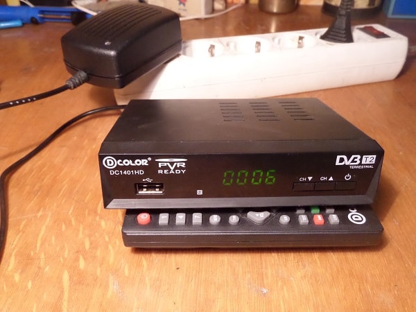
I'll make a reservation right away that this method is not suitable for all models of consoles, but for many, since they are often made according to a scheme very similar for this case. Everything will be based on a specific example of a set-top box from the D-Color company, namely the DC1401HD model. So by understanding this "high technology" you can repair your digital TV box yourself.
Fast navigation through the article
What is a sign that it is the power supply unit that has failed in the console, and not something else? If the set-top box connected to the outlet does not show any signs of life, neither the digital indicator nor the LED on the front panel is lit, then with a probability of 99% the reason is in it, in the power supply.
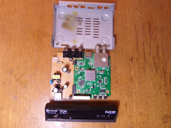
If, at the same time, the warranty period has already expired, then you can safely do the disassembly. As the experienced masters say, "An autopsy will show" I think you will deal with this part of the work without a detailed description, just be careful, usually two screws on the back wall, sometimes also on the sides allow you to release and open the top cover. Plastic latches on the sides and bottom hold the front panel, and the board itself is also fixed with screws to the bottom of the case and in the area of the connectors on the back of the case.
So, the set-top box is disassembled, the power cord is also removed from the connector, it is no longer needed. On the bottom of the case you can see traces of a "fire" that left behind a burnt-out power supply unit.
P.S.The power supply unit here is not a separate unit, as you might think from the name, but a section of the board on which radioelements are located that provide the required power supply voltage for the set-top box.
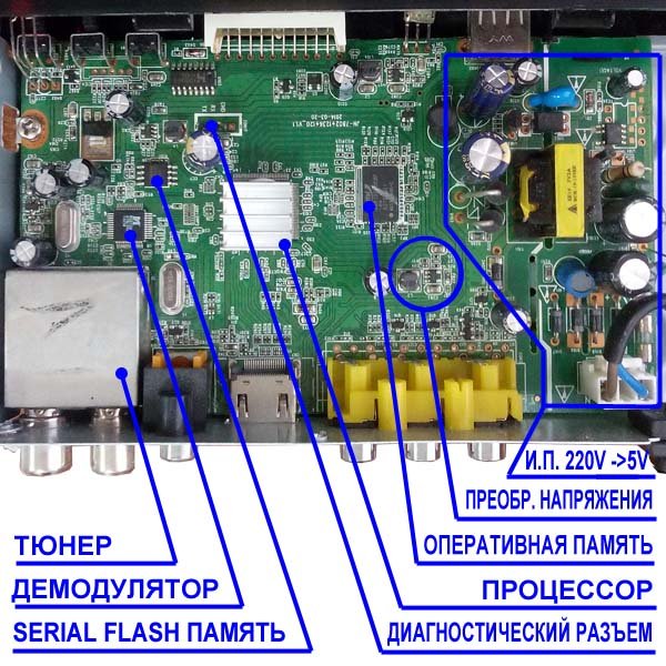
I will outline the general picture, and for those who are already a little versed in radio engineering, this will already be enough to grasp the basis of the idea and repeat. So, the power supply circuits of this set-top box give out only one voltage - 5 Volts. Since this circuit has burned out and repair may be impractical (in terms of the total cost of radio components and repairs), that is, a simple solution. Replace the internal power supply with an external one. It's not very difficult!
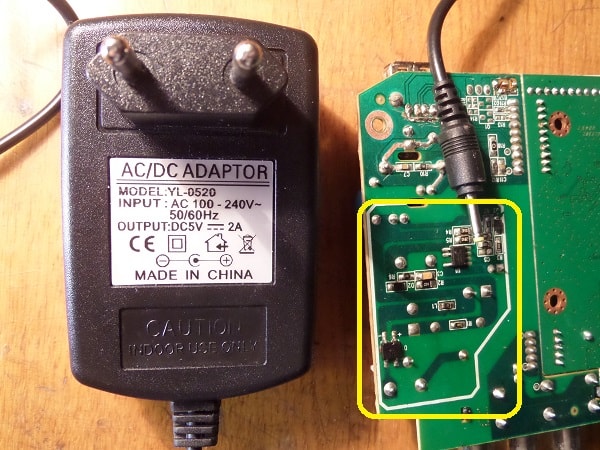
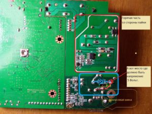
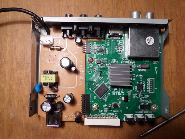
In the photo above, with a yellow frame, a section of the power supply unit that has failed is highlighted. The board has already been washed, so no traces of burning are visible. By the way - Among the repairmen, the expression "Burnt out" does not always mean literal burning with charring and other similar manifestations, it only means that the radio components are out of order.
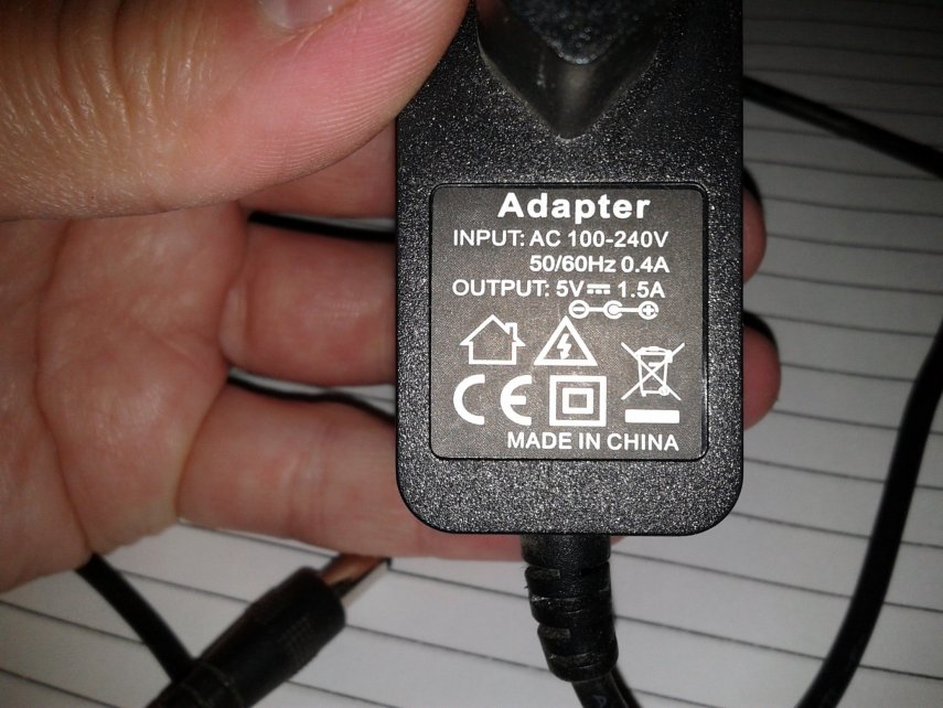
For our repair, you will need to purchase an external power supply with an output voltage of 5 Volts and capable of delivering a current of 1.5 or better 2 Amperes. Now there are a lot of similar ones and can be purchased not expensively, or maybe you have a similar one, for example, an unused charger from a tablet or smartphone.
When a suitable adapter is available, it remains to find the desired point on the set-top box board and, observing the polarity, apply voltage to it from the external power supply. Everything! It remains to lay and secure the wire, or you can organize a detachable connection, as you like. I think the basics are clear, let's get down to the details.
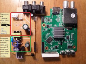
Just a little bit of basics for those who are not in the subject, so that you can figure it out. Pay attention to the photo. Click to enlarge.
In short, the power supply consists of:
- The primary "Hot" part - Hot, it is called because it is dangerous, connected to the mains voltage of 220 volts. Please note that even after disconnecting from the outlet, for some time, there is a charge that can bring brr .. unpleasant sensations if you climb there. But in our case there is no need to climb there and we will not connect it to the outlet either.
- Secondary part - Safe there, there is a galvanic isolation from the mains. In the given example, at the points indicated in the photo, a voltage of only 5 Volts comes out from the rectifier diode.
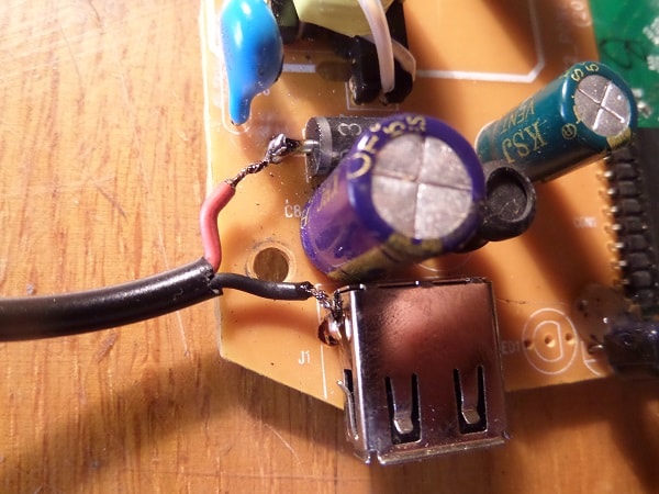
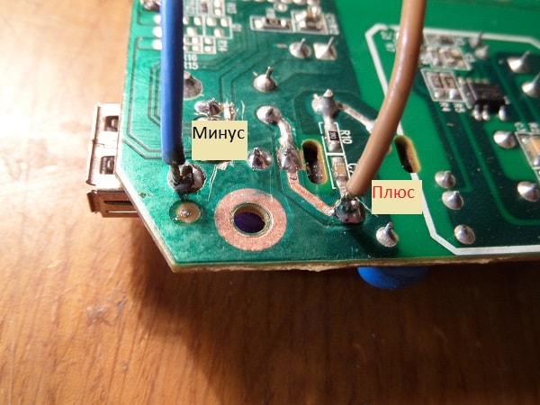
In the purchased, external power supply (at least 1.5 amperes, 5 Volts.) We bite off the plug, clean the ends of the wires and, having determined the polarity, we solder them: Positive to the diode terminal, on the side where the strip is drawn on it, and the negative to the common bus - the body of the USB port will be a convenient place for this. If you do not know how to determine the polarity, even without a device, see additional materials at the end of the article.
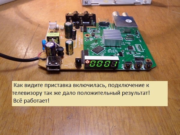
We connect the new power supply to the network, take it out of standby mode, check what happened.
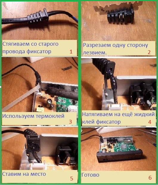
All OK! It remains to lay and secure the wire so as not to accidentally pull it out, collect everything in a heap and use it. In the end, it will look like this.
If you need ideas on how to attach the wire to the box? How to determine polarity without a device? Or how to solder the wire from the bottom of the board? - Then these additional materials are further in the text.
For those who have a multimeter, it will not be difficult to determine the polarity of the power supply, but what about those who do not have this device?
There are several simple ways:
- You can determine the polarity by the color of the wires. There is a rule - the Red wire is a plus, respectively, the other wire is a minus. This is almost always the case! Nearly! Sometimes there are exceptions, either the wires do not understand what color, or the rule has been violated.
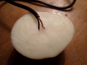
- There is another way, it will be needed - just don't laugh ... potatoes. Yes, yes, raw potatoes! The method is as follows.Cut the potato in half and stick the bare copper wires from the external power supply into it, at a distance of about 5 mm from each other. We plug the PSU into an outlet and wait. With the adapter voltage of 5 volts, it took about three minutes for a visible result. Click on the photo to enlarge.
The potato around the positive wire begins to turn green, so you can accurately determine the polarity without instruments.
In the first, simplest version, the wires were soldered from above, directly to the terminals of the radio components, but you can do it a little differently, run them from the bottom.
In this case, the wire to the case will pass under the board, from the bottom.
On this occasion, hastily prepared a small photo report with a short, step-by-step description of the actions. Hopefully this will be enough.
By the way! Such alteration can be arranged in order to adapt the digital set-top box for use in a car. You just need to use a 5 volt 2 ampere car adapter.
That's all! Success to everyone! I would be glad if this information helps you with something!
A digital TV set-top box allows you to play high quality video on a conventional analog TV. Also, in addition to the image, the set-top box is capable of "producing" surround stereo sound.
The first consoles had a minimum of functions and a fairly decent size. But despite this, they were of better quality than the latest models.
The manufacturer, trying to reduce the size and weight of the device, began to save on some parts of the electronic circuit, which significantly reduced their reliability. In this regard, breakdowns of this type of consoles have become commonplace.
This article describes a common breakdown of the console and a method for its elimination.
The prefix worked great and at some point the picture and sound just disappeared. In this case, the red LED on the front panel of the device was lit. True, the glow was not as bright as before.
The set-top box did not react to the remote control in any way.
So where should you start?
As practice shows, most often the power supply fails.
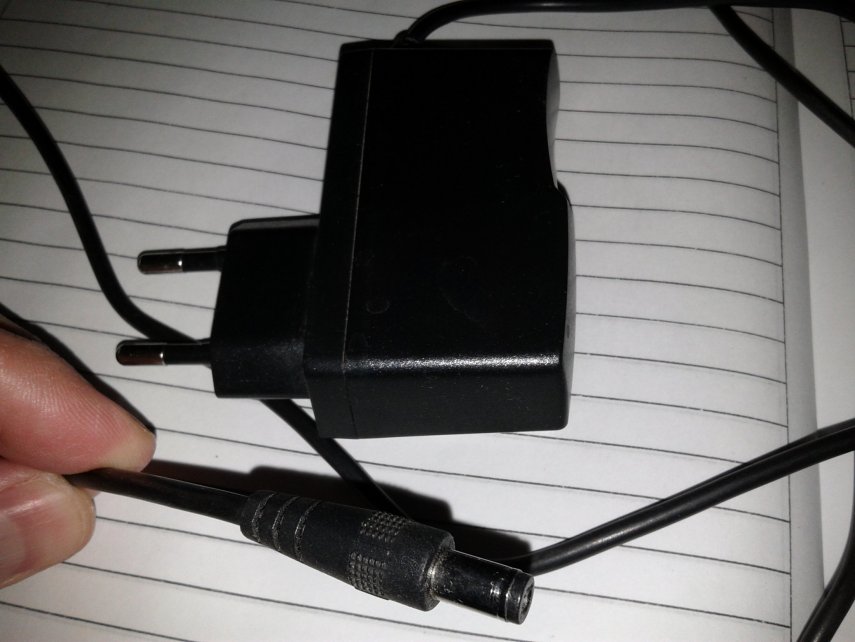
In this device, it is external and there is no particular difficulty in checking it.
We take any device that measures voltage. It can be a tester or multimeter.
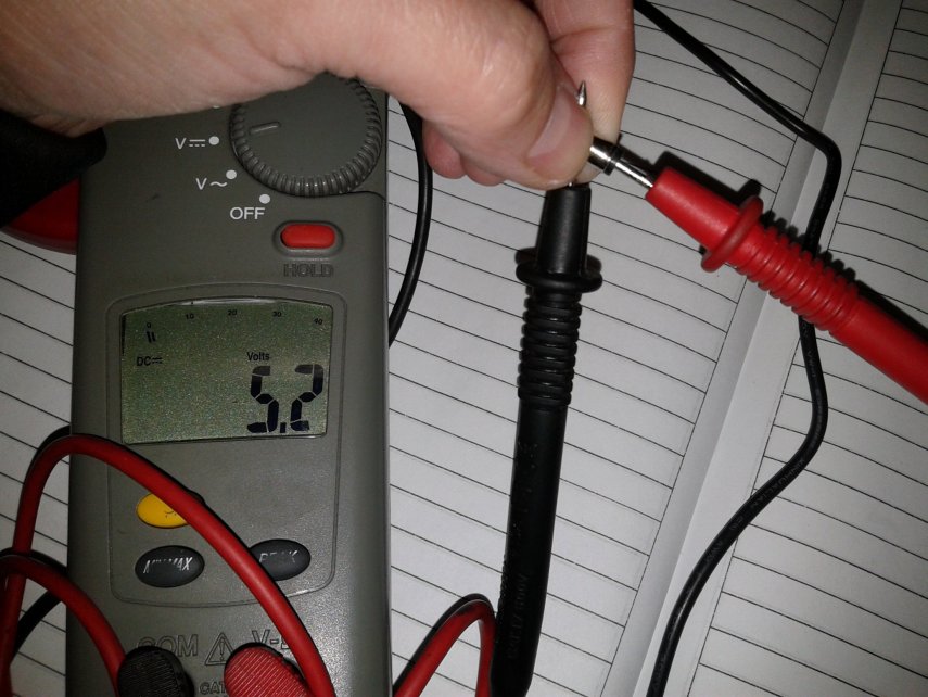
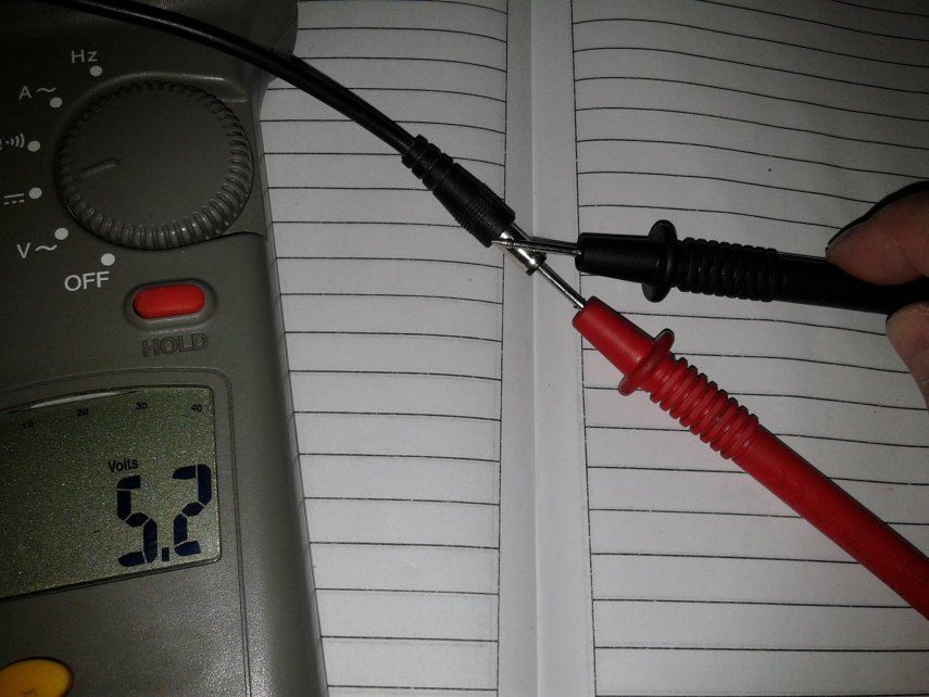
In our case, a digital multimeter was used for measurement, set to measure a constant voltage.
We turn on the power supply to the network and connect the pins of the device to the outlet on the cord.
Oddly enough, the device shows a voltage of 5.2 volts, which is a normal indicator for the operation of the console.
We turn to the disassembly of the T2 set-top box itself.
At first glance, it seems that it is not collapsible. Nowhere are there any screws or recesses for them.
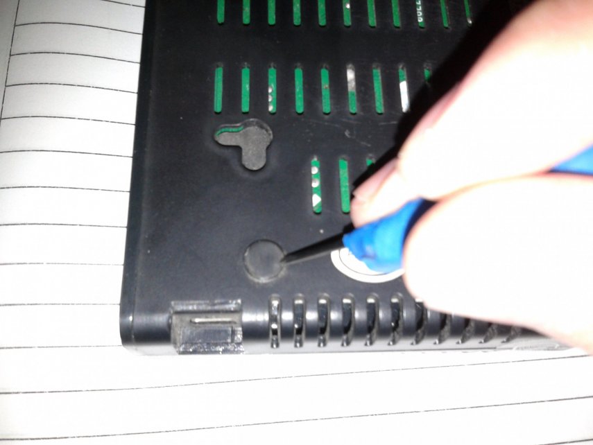
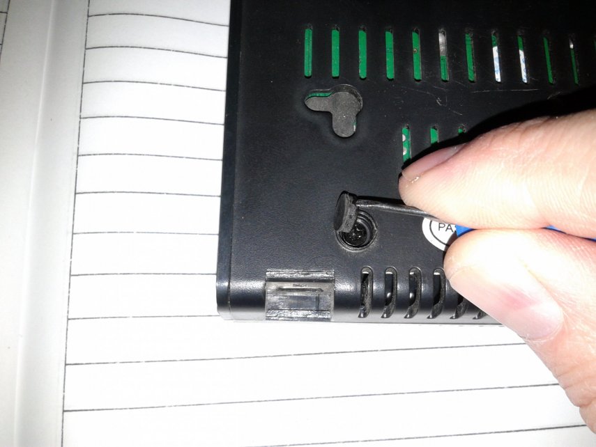
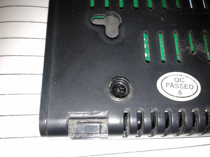
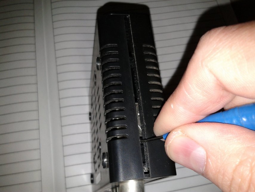
But if you turn the attachment over, you can see two rubber feet at the bottom. Under such rubber bands, the screws for fastening the case are usually hidden.
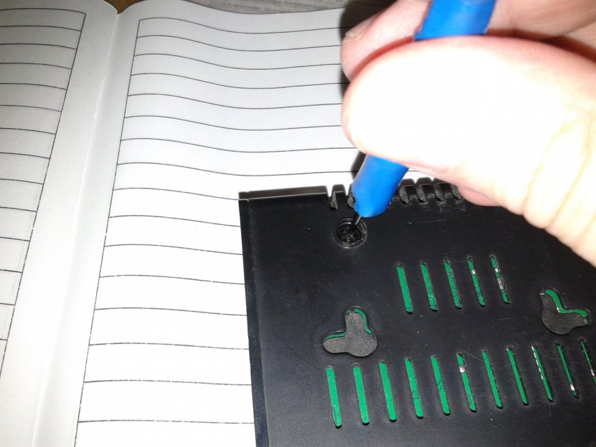
By prying one of the legs with a screwdriver, you can see that there are indeed screws under them.
Unscrew the screws with a Phillips or small straight screwdriver.
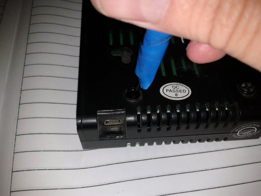
Now, using the same straight screwdriver or knife, we separate the two parts of the case. To do this, insert a screwdriver into the junction of the two halves, and with vertical movements of the tool, release the plastic latches.
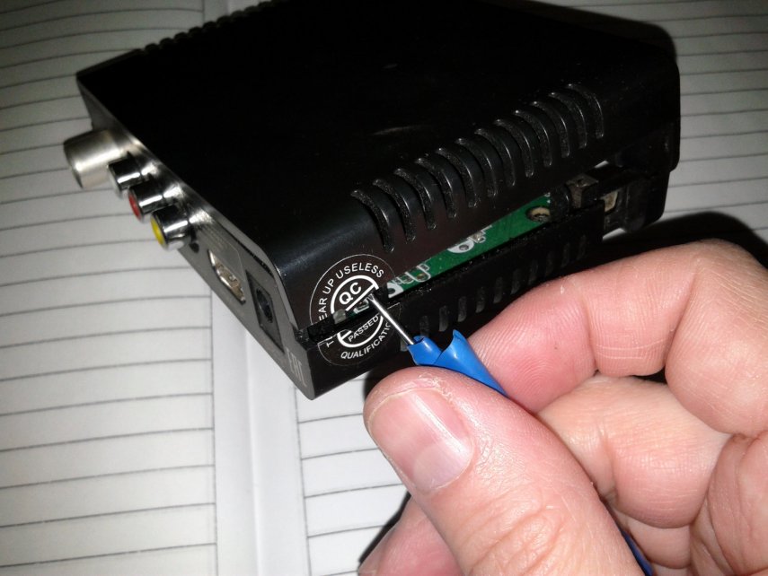
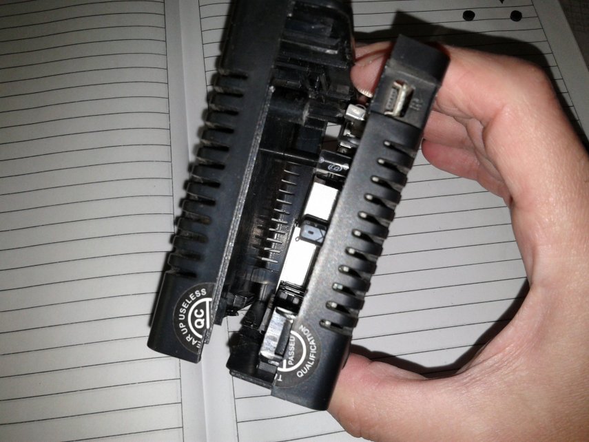
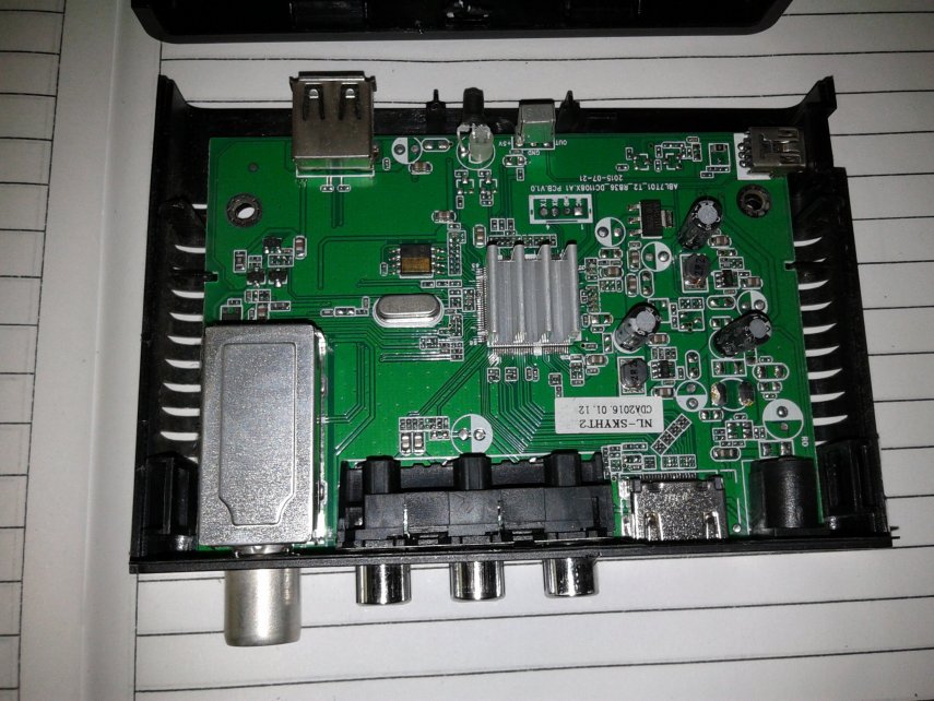
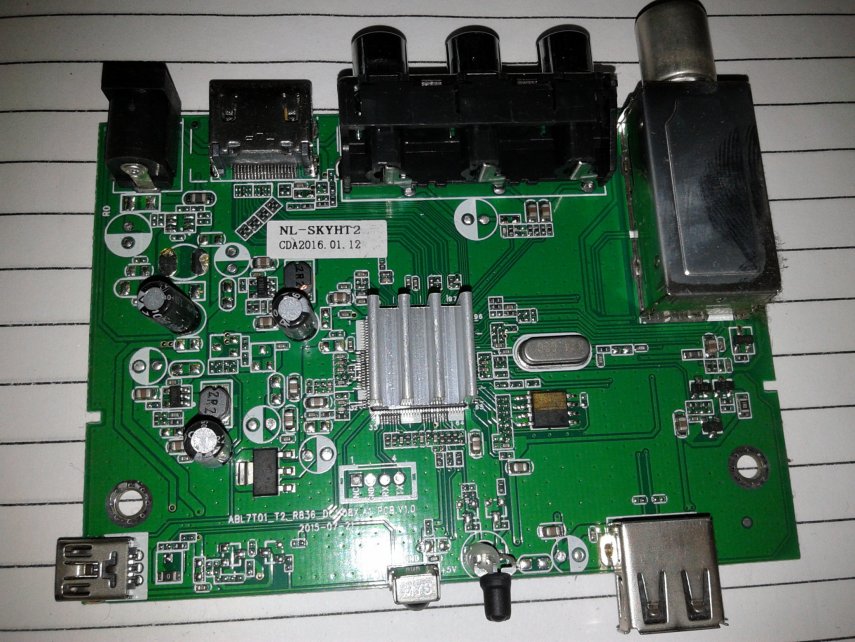
For a closer inspection, you can easily remove the board, since it is not attached to the bottom of the case.
After removing the board, using a magnifying glass, you can inspect it for external damage to electronic elements and cracks in the soldering points.
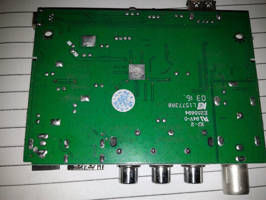
Especially carefully inspect electrolytic capacitors for swelling from above or electrolyte release from below.
When inspecting this board, no external damage was found.
Since the LED on the panel did not glow brightly enough, the suspicion of a malfunction still fell on the power supply.
Therefore, we return to it again.
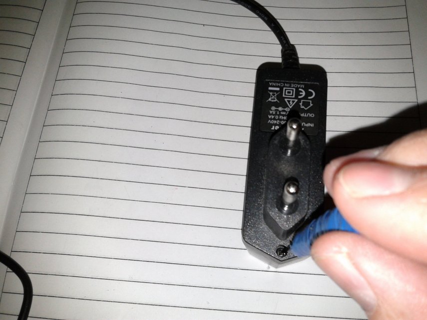
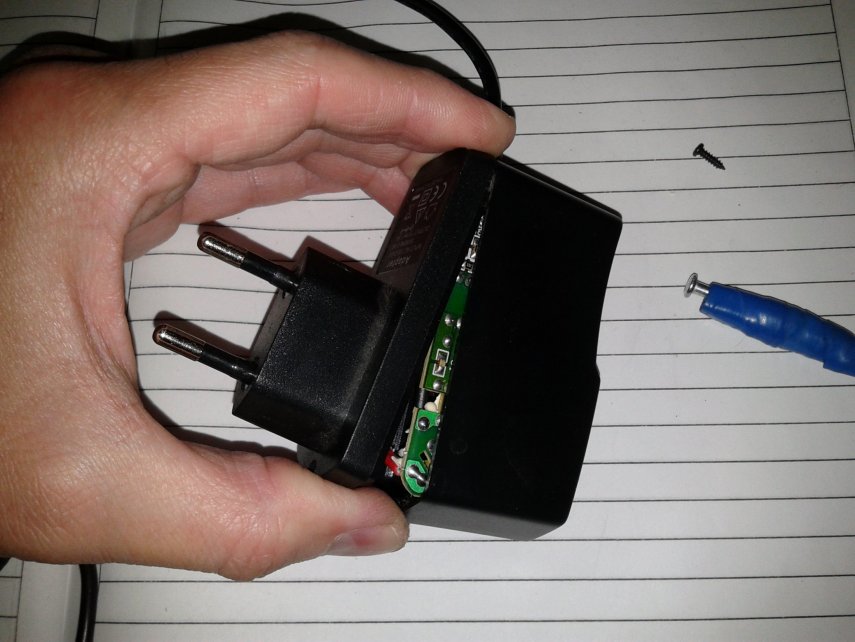
The unit body is fixed with one screw. We unscrew it with a suitable screwdriver. It can be straight or cross, the main thing is that its tip goes into the landing recess.
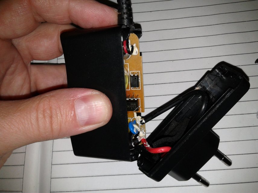
When the screw is unscrewed, pull back the top of the cover to release the latch from the bottom.
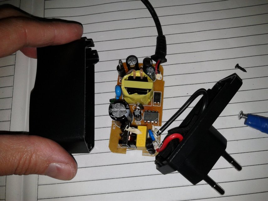
Remove the cover and pull the board out of it.
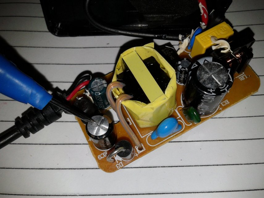
The photo shows its upper part with circuit elements.
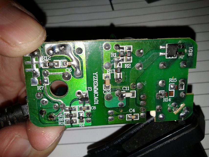
The electronic components must be carefully inspected for damage.
Usually, an electrolytic high-voltage capacitor in a pulse generator circuit breaks down. Due to voltage fluctuations in the network, its insulation does not withstand, and it swells or burns out.
But in this state of affairs, at the output of the power supply, there would be nothing. And since there is an operating voltage of 5 volts, it is most likely intact.
Upon further inspection, a swollen capacitor was nevertheless found, but it was in the secondary circuits, that is, to smooth out the ripple of the 5 volt output voltage. Despite the fact that it was damaged, the tension did not decrease.
Therefore, it was impossible to immediately determine the breakdown of the power supply without disassembling it.
Unless using an oscilloscope on which you can see an irregular voltage waveform. But not everyone has such a device.
Consequently, this irregular shape did not allow the electronics of the set-top box to work in normal mode.
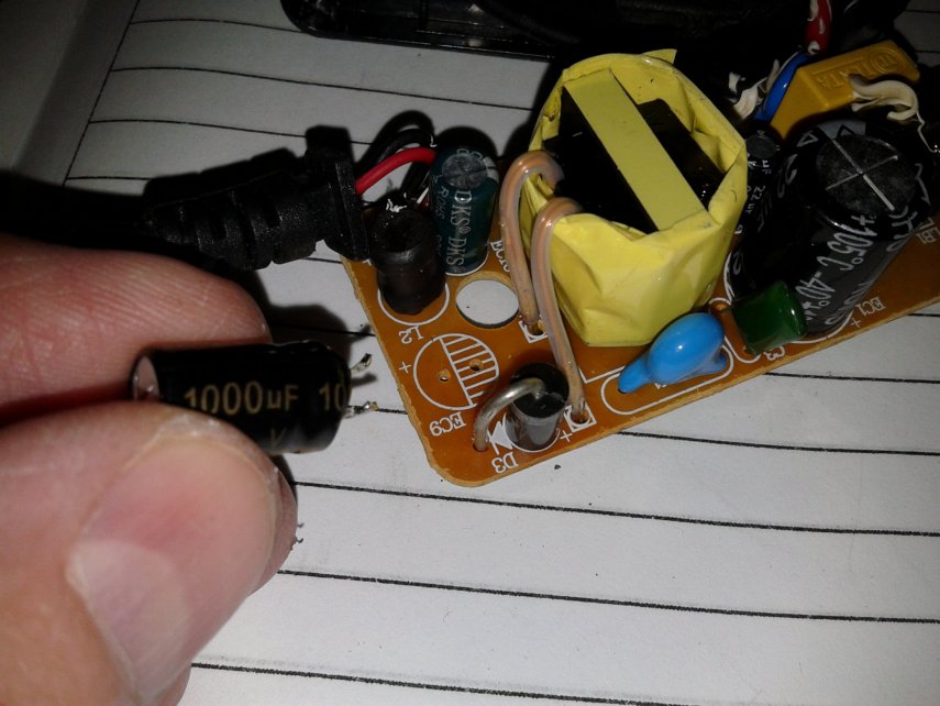
We change the capacitor to a known good one. The swollen capacitor had a capacity of 1000 microfarads and was rated for a voltage of 16 volts.
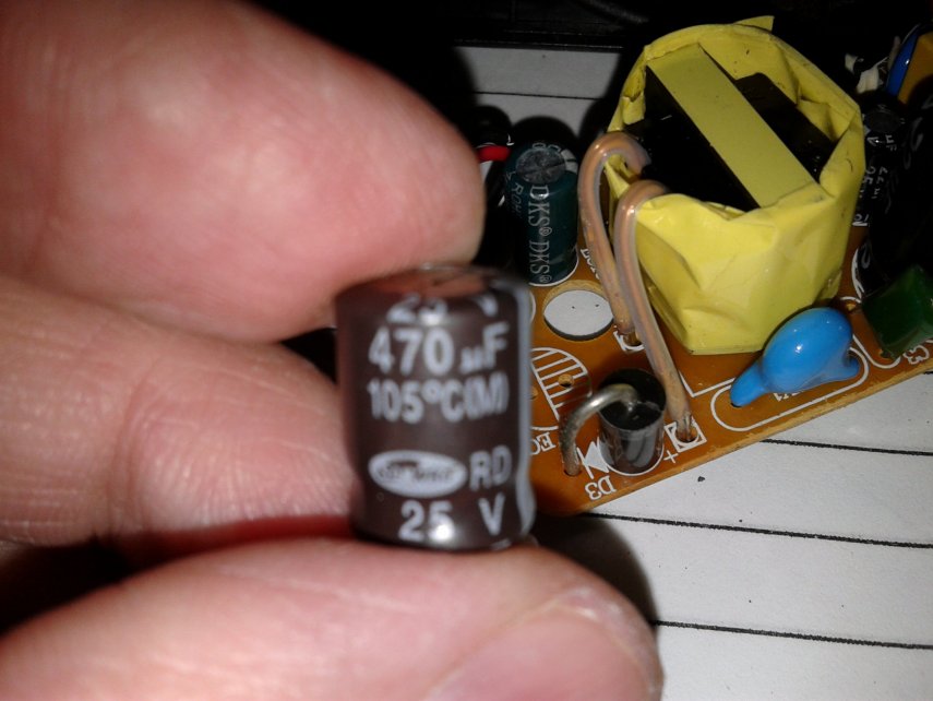
When replacing, you can put the same one, but it is better to choose a higher voltage. A 25 volt 470 microfarad capacitor was found from old stocks.
The capacity is certainly less, but this will not particularly affect the quality of the device. If there is a 1000 microfarad capacitor, you can put it, provided that it fits into the seat of the old one.
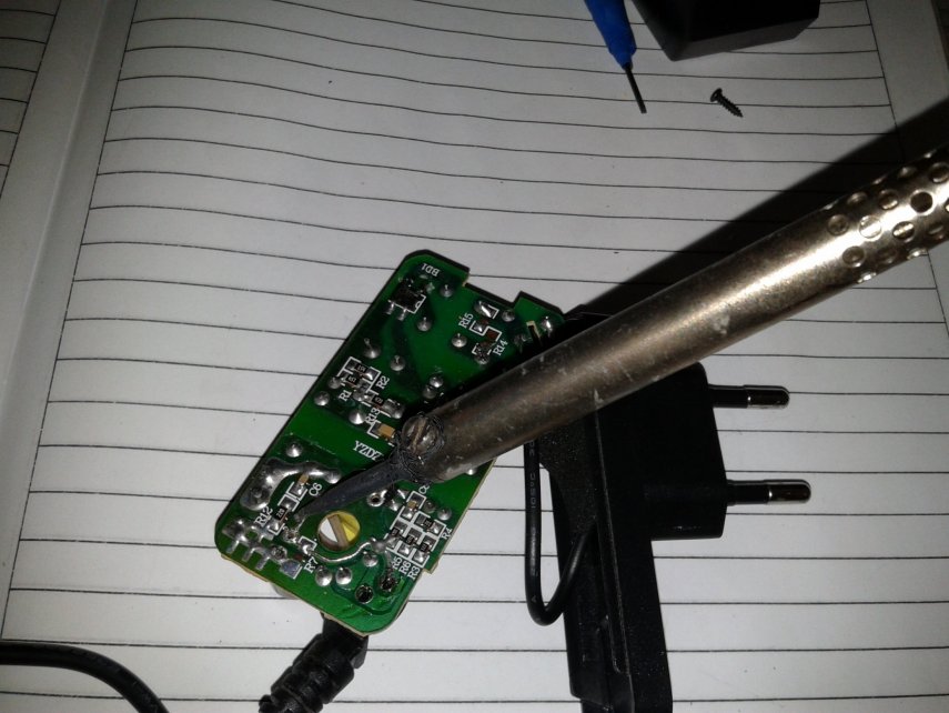
So, we solder the non-working part with a soldering iron, and change it to a new one, while preparing the landing holes.
It is very important to respect the polarity. Having inserted the legs of the part into the holes, we seal them with tin POS-60.
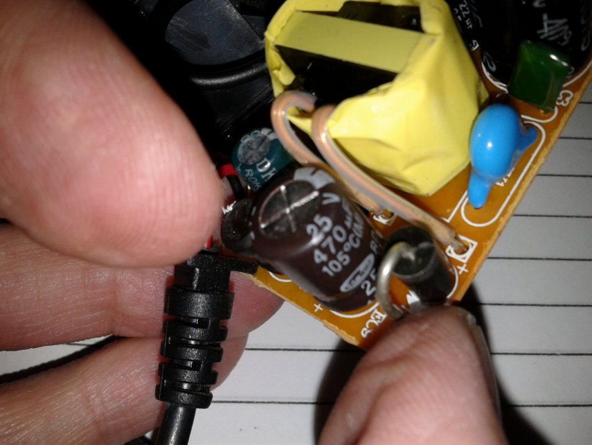
With the help of a magnifying glass, we examine the place of soldering, for the presence of short circuits between the tracks. If necessary, remove them with a needle or an awl.
After that, we collect the block and connect it to the network. We measure the output voltage.
As you can see in the photo, the voltage value has not changed at all.
Now, we connect the power supply to our T2 set-top box already connected to the TV.
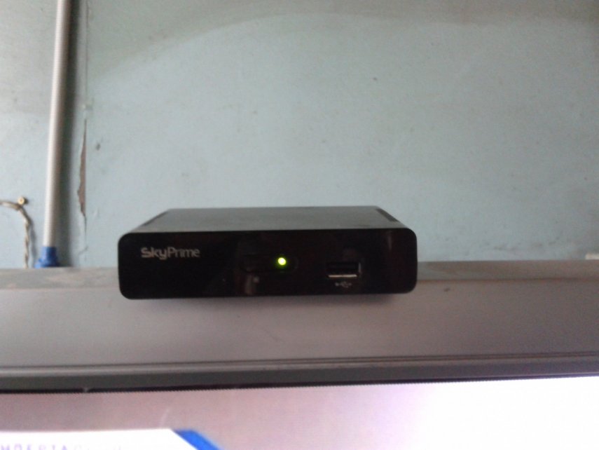
It was immediately noticeable that the brightness of the LED has increased, approximately twice, and this was a good sign.
When an image appeared on the TV screen, it became clear that the problem was precisely in the capacitor, and its replacement completely restored the operation of the set-top box.
No streaks or distortions were found on the screen, which meant that the repair was successful.
Terrestrial digital television increasingly penetrates the vastness of our large country, and in the hinterland without the use of "secret military" technologies, literally simple banal "radios" of a classical antenna can catch 20 channels of digital television. However, as the analysis of online forums shows, dvb t2 set-top boxesare usually of Chinese origin and are by no means of the highest quality.
Quite recently, just such a “apparatus” came to me for “home repair”. Unfortunately, the device for receiving digital broadcasting did not turn on corny ... There was no standby or operating mode. Trial measurements with a tester showed the missing voltage after the secondary winding of the transformer, replacing the PWM in the primary part of the power supply circuit, which is structurally made on the same board with the rest of the electronic filling, did nothing. Having removed the transformer from the circuit and ringing the windings, I confirmed my fears about the malfunction of it.Diving into a problem called repair dvb t2 consoles, I realized that the most rational solution in this situation would be to replace the power supply with an external one with the required power characteristics. In most cases, the main circuit is powered by a stabilized voltage of 5 volts, as for the current consumption, in standby mode it did not exceed 200-250 milliamperes, and in working condition it was more than 800-900 mA. Since there are no 5 volt power supplies lying around at hand, the only available solution, in my case, was a charger from a Lenovo smartphone.
In the diagram, we easily find minus / mass, and solder the plus to the output from the diode
When the external power supply unit dvb t2 was soldered, the set-top box briskly started blinking with the set indicators ...
So if the repair of the dvb t2 set-top box is caused by a failure, in one way or another, of the native power supply unit, then sometimes a reasonable choice would be to switch to a power source made in an external design with characteristics suitable for a specific device.
For this I say goodbye there is nothing more to write about
Maslenkov Andrey
Digital TV T2 is gaining momentum in popularity. And this is natural, digital television is replacing analog television and this is an irreversible process. Moreover, in the near future, analogue broadcasting will be discontinued altogether. What should users who have TVs without a T2 receiver and no cable TV do? The answer is simple - buy a T2 prefix. To date, the price of T2 consoles has dropped a lot and does not look sky-high. The advantages are quite big: you get a lot of channels in digital quality, without a monthly fee, at minimal cost and without buying a new TV. Only by comparing the quality of digital and analog TV will you never regret your choice.
Quite a lot has been written about the choice of T2 receivers. Moreover, new models are constantly being released. I would advise you to take an inexpensive, but new model, after reading reviews on the websites of online stores. As a rule, any receiver works, but the antenna is of great importance. Even if you are not far from the TV tower, but block high-rise buildings, etc. - and this is almost always, then a good antenna is a guarantee of trouble-free (and most importantly - nerve-racking) high-quality reception of the maximum number of digital TV channels.
But an expensive antenna is not always a good antenna. Especially if you have a distance of 50 km or more from the TV tower. The shops offer “special” antennas for T2. In fact, there is nothing “special”, you need a good antenna for the DMC range. If you still have an old DCM antenna, first of all try to connect it. The widespread "Polish" antennas are not suitable for receiving digital T2 channels.
I propose a proven version of a simple, at the same time well-proven, homemade antenna for T2... The shape of the antenna is not new, it has been used for a long time also when receiving the DCM of analog television, but the dimensions are optimized for receiving digital T2 channels.
It is worth noting that the Internet offers a large number of options for homemade antennas for T2: from beer cans, from the antenna cable itself, a converted Polish one, etc. This is for the completely lazy, well, you should not expect quality from such antennas.
So. The long-known “eight” was taken as the antenna shape. The antenna body is made of any conductive material of a suitable cross-section. It can be copper or aluminum wire with a thickness of 1 to 5 mm, tube, strip, bus, corner, profile. Copper is of course preferred. I used 6mm copper tube. Copper wire is also a good option. I just had such a pipe.
The outer side of the square is 14 cm, the inner side is slightly smaller - 13 cm. Due to this, the middle of the two squares does not converge, we leave a gap of about 2 cm.
All you need is a tube, wire or other material, 115 cm long (this is with a small margin).
The first section is 13 cm + 1 cm for the loop (for strength) if made of wire, or riveted for overlapping soldering for the tube. The second and third - 14 cm each, the fourth and fifth - 13 cm each, the sixth and seventh - 14 cm each, and the last eighth - 13 cm + 1 cm, again for connection.
We clean the ends by 1.5 - 2 cm, twist two loops behind each other, and then seal the joint.
This will be one pin of the cable connection. After 2 cm, another.
From a copper tube it looks like this
The tube is a little more difficult to bend, but great accuracy is not required from us. Small flaws in the shape do not affect the performance of the antenna. But the fact that the area of the conductor is increasing is a plus. Well, the conductivity of copper is higher than that of aluminum and, moreover, steel. The higher the conductivity, the better the antenna's reception.
The joint prepared for soldering is pre-riveted and cleaned. For soldering, you must use a powerful soldering iron (from 150 W). Simple radio amateur for 30 watts. do not solder. Soldering acid can be used.
Check the geometry again and solder the connection
Then we solder the TV cable. Where to solder the central core, where to braid, does not matter. Everything simple DIY antenna for T2 ready.
If you are not particularly bothered by the aesthetic appearance, you can simply fix the antenna on a glazing bead or any other handy holder. This antenna was located in the attic, so the simplest mounting method was used - electrical tape. If the antenna will be placed outdoors, take care of more aesthetic and reliable fasteners.
This is a variant of the T2 antenna made of aluminum wire with a diameter of 3 mm. Fixed with one screw on the window. The distance to the TV tower is about 25 km. True, the 6th floor, I did not check it below, but under these conditions the signal level is 100% and the quality is 100%. The cable is old, 12 meters to the TV. Receives all 32 channels. At first I was worried that it was not copper, but as it turned out, in vain. Everything worked out great on ordinary aluminum wire (which was available). That is, if you have a zone of confident reception, then you can not bother and feel free to use aluminum (I don’t know, maybe steel will do).
This antenna does not use any amplifiers. It is set up very simply - you turn it according to the maximum signal level and quality on the channels of your tuner. Check the rest of the channels and fix the antenna. If the reception is poor, you can experiment with not only turning, but also changing the location and height. Very often, the signal can be many times stronger, when the antenna is displaced by only 0.5-1m to the side or in height. Good luck - the antenna has been tested - it is 100% efficient and better than at least half, or even more purchased antennas, where they save on everything and sell bullshit for good money.
In this article, we will tell you how to properly connect digital television to your TV. Here we will only talk about connecting terrestrial and cable TV (setting up satellite broadcasting is beyond the scope of this material).
Attention! All cable connections described below should be made with the power supply disconnected to prevent damage to them.
Many modern Smart TVs have a built-in receiver for decoding a digital signal. For example, a line in the characteristics of a DVB-T / C / S TV indicates that this TV model supports the reception of terrestrial, cable and satellite digital television without an additional set-top box. At the same time, some standards are already outdated, so a TV with a built-in DVB-T module will not be able to receive digital channels of the current DVB-T2 standard.
- Antenna of the decimeter wavelength range (UHF) or a universal all-wave antenna designed for different ranges.
- Digital tuner (receiver) DVB-T2 or TV with a built-in module of the same standard.
- Connecting cables.
Separately, it should be said about the broadband Polish antenna, the so-called "grid" or "Pole". If you want to use it to receive digital television, you will need a little modification, namely, replacing the standard amplifier with a balun. This will cut off the unnecessary range and tune it exclusively to decimeter waves. Or buy a "Polish" with an already installed symmetrizer.
Since not all TVs have a built-in tuner, we will consider a connection diagram using a digital set-top box... Such an instruction will be more universal and will work in most cases.
1. Connect the RF antenna cable to the antenna input of the digital set-top box marked with the letters IN or IN.
2. To connect the set-top box to your TV, we recommend using HDMI. This interface is specially designed for digital signal and provides the highest picture quality.
To connect a digital TV box to the old TV you can use the AV connectors for an RCA (cinch) cable or a coaxial connector. For older TVs, there are no other options.
3. How to tune digital TV channels on your TV
- Select signal source. To do this, press the button on the remote control marked with the words SOURCE, INPUT, TV / AV or a square with an arrow and select HDMI or AV from the list provided, depending on the type of connection. Also, the signal source can be selected through the TV settings by pressing the button with the house or the word MENU on the remote control;
- as a result, you will be taken to the digital set-top box menu. As a rule, all the necessary parameters are already set here by default, so the digital channels on the TV are tuned in automatically.
To do this, just use the navigation arrows to select the item "Autosearch" and press OK. After finding all the available channels, you can start watching. The setup is complete.
Connecting a TV with a built-in digital tuner follows a simplified diagram:
- Connect the RF antenna cable directly to the antenna input of the TV.
- Activate the digital tuner in the TV menu.
- Perform automatic tuning of digital channels.
To connect this type of TV, you need a digital cable or universal (hybrid) receiver. Unlike a regular terrestrial one, it is equipped with a special PCMCIA slot for a CAM module with an access card, which allows you to unlock a paid package of channels purchased from a cable TV operator.
Many modern Smart TVs with a built-in digital receiver already have a PCMCIA slot, so no additional equipment is required in this case.
You can also use a special card reader to read CAM modules, but due to the large selection of hybrid digital receivers, these devices are used less and less.
Otherwise, to connect a digital TV set-top box to a TV and set up digital TV channels, follow the instructions described above, since almost all receiver connectors are identical. Unless in this case, instead of an RF antenna cable, the provider's cable is connected to the input of a digital set-top box or TV.
Ideally, one digital receiver means connecting one TV to it, so the optimal, although not the cheapest option, would be to purchase a separate receiver for each TV. In this case, the RF antenna cable is connected to a splitter (splitter) with two or more outputs, and then the signal goes separately to each receiver. The diagram of such a connection is shown in the figure:
You can also simply connect two TVs to one digital set-top box (receiver) using free connectors. For example, HDMI is for one, and tulips are for the other. It should be remembered that in this case, the same decoded signal will be received on both TVs. Therefore, the image on the screens will be synchronous.In addition, you will need long cables to space the TVs to different rooms.
| Video (click to play). |
Another way is to use an RF modulator, which, through a divider, will supply a separate decoded signal to each TV. But often the cost of such a device is several times higher than the price of a conventional digital terrestrial tuner.

