In detail: do-it-yourself repair of the Ural 4320 frame from a real master for the site my.housecope.com.
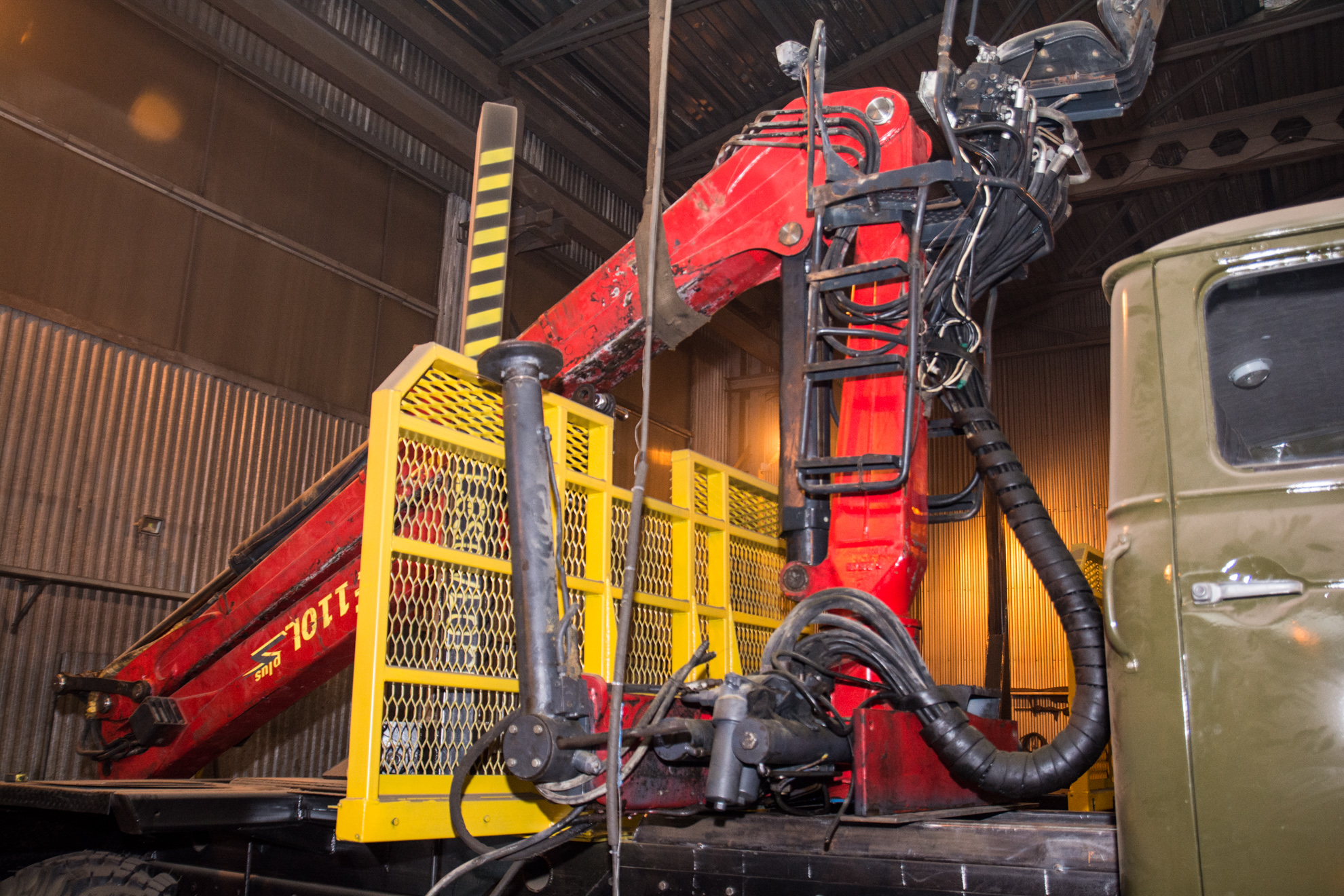
A timber carrier based on the Ural-4320 with a YaMZ-238 diesel engine and an EPSILON E110L hydraulic manipulator after overhaul and modernization has excellent performance characteristics. Therefore, this technique is in great demand in the logging industry.
Re-equipment of the Ural-4320 conversion vehicle into a timber carrier has been completed:
- complete disassembly of the car;
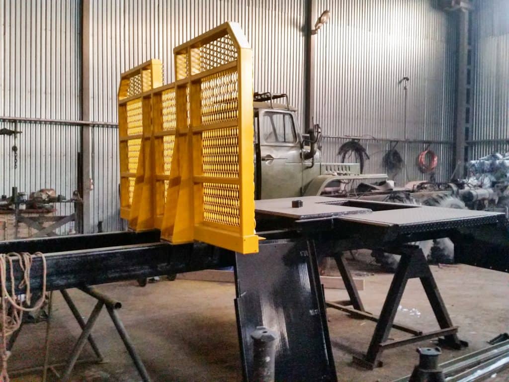
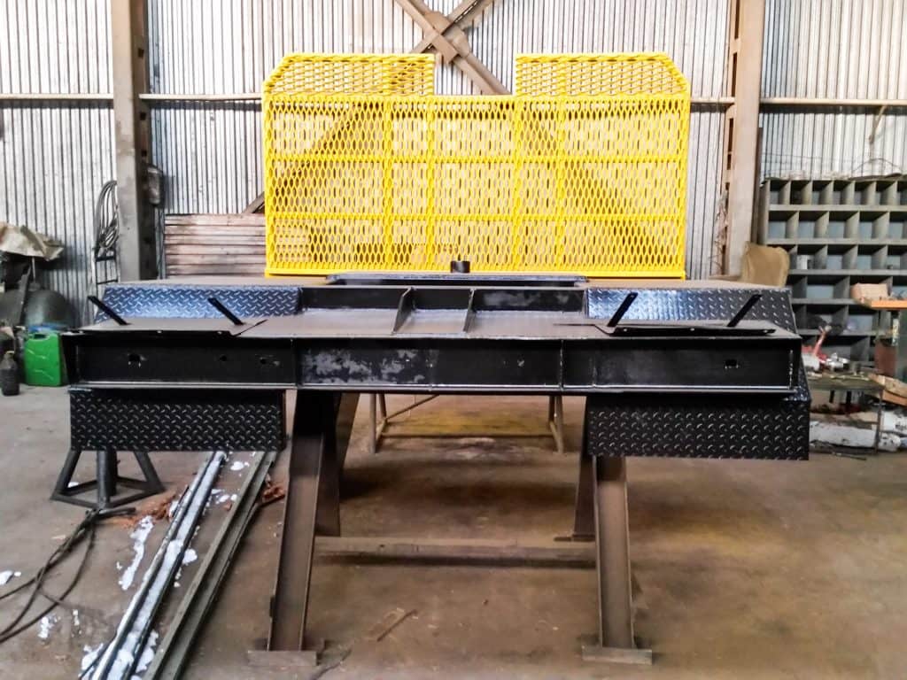
- timber-carrying equipment was manufactured: subframe, bunk, protective screen;
- diagnostics of all components and assemblies, replacement if necessary.
- diesel atmospheric engine YaMZ-238;
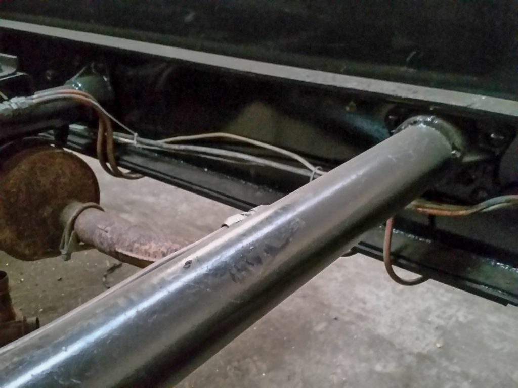
- reinforced frame inside the side members;
- reinforced frame for the installation site of the hydraulic manipulator;
- reinforced front springs.
In the process of overhauling and converting the car into timber truck with hydraulic manipulator work was carried out to dismantle all the main components and assemblies, as well as diagnostics of their technical condition.
Loader vehicles must meet high reliability indicators when operating in harsh Russian conditions. In order to ensure the necessary parameters, work was carried out on double reinforcement of the frame:
- reinforcement of the frame inside the side members;
- reinforcement of the frame in the place where the hydraulic manipulator is installed.
When carrying out a major overhaul of the frame of trucks, a wide range of works is carried out:
- rinsing and cleaning from old paint;
- replacement of worn out brackets with new ones;
- priming, painting and drying in a drying chamber.
The chassis of the timber truck must withstand high operating loads, especially on the front axle of the vehicle. Before installing the forestry equipment and hydraulic manipulator on the chassis, work is carried out to strengthen the car's suspension, diagnostics and replacement of the necessary components:
| Video (click to play). |
- flushing and complete disassembly;
- adjustment of newly restored units in accordance with the regulatory documents of the manufacturer with further running-in at specialized stands;
- installation of new front springs, spring lugs, step-ladders, rear springs, spring lugs and step-ladders;
- installation of new balancer bushings, gaskets, rings and cuffs, installation of new shock absorbers;
- priming, painting and drying.
- dismantling with complete disassembly of all units;
- inspection, troubleshooting with the replacement of rejected working gears, shafts, housings;
- assembly using new bearings, gear parts, shims and seals, bushings, collars, washers and fasteners;
- adjustment of the assembled units in accordance with the regulatory documentation for each unit with test running on specialized transmission stands;
- priming and painting of units;
- filling with lubricants upon completion of installation.
During the overhaul of a car, an extensive range of works with the cab is carried out:
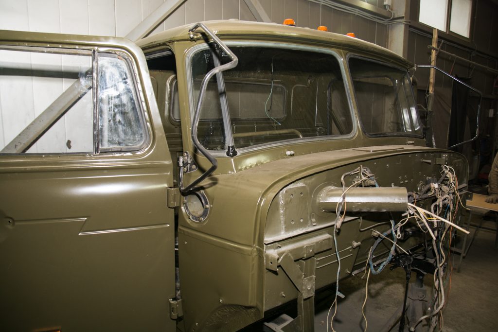
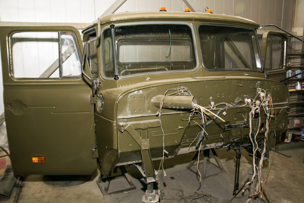
- complete disassembly of the cab, removal of the old paintwork;
- replacement of deformed and corroded cab parts;
- priming, painting, treatment of the bottom of the cabin with bitumen mastic and drying in a drying chamber;
- installation of a new interior, seats, dashboard, wiring and cab trim;
- replacement of deformed empennage elements;
- priming, painting and drying of plumage elements in a drying chamber;
- subassembly of plumage and installation on the car.
New steering components are being installed: steering gear, power steering, power steering pump, steering shaft.
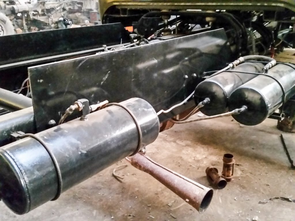
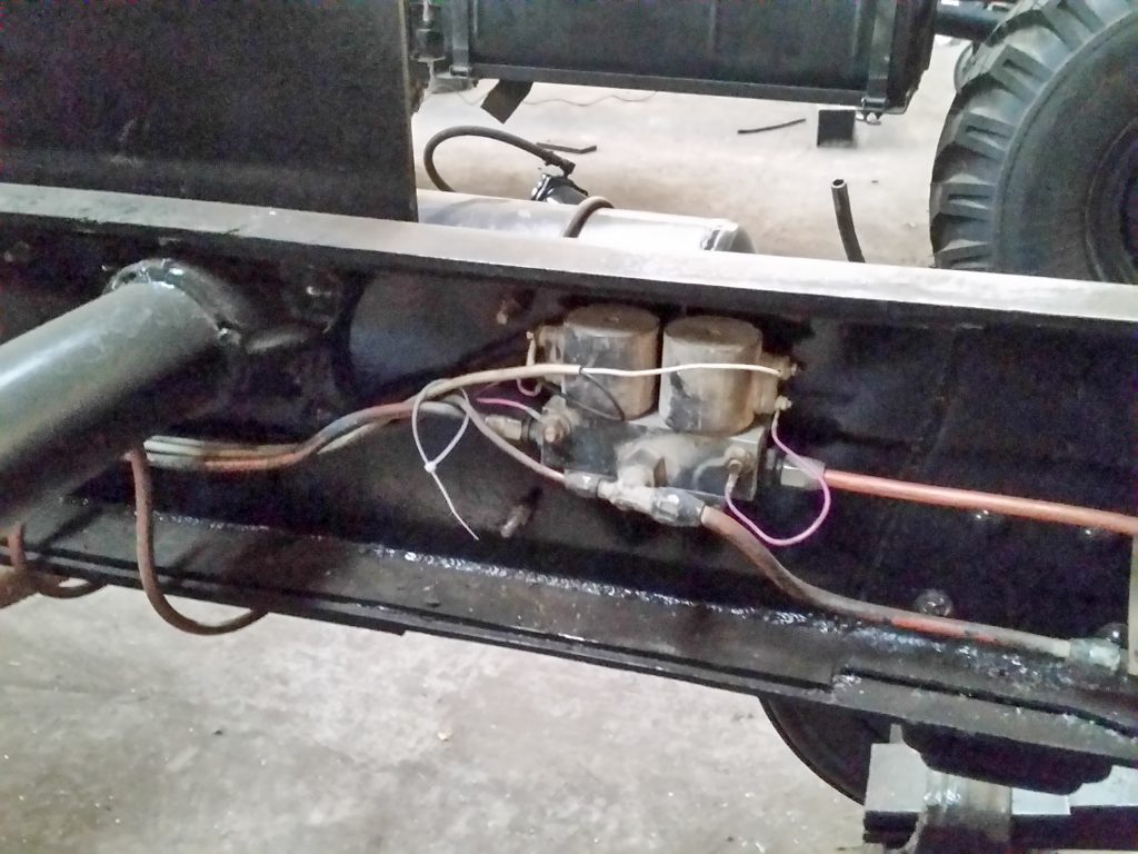
Only new components of the brake system are installed: brake valves and valves, pneumatic hydraulic booster, brake master cylinder, working brake cylinders, brake pads, hydraulic and pneumatic lines.
The subframe of the timber carrier is the base for the placement and fastening of the components of the logging equipment. The company "SPETSLESAVTO" is engaged in the production of subframes for trucks.
The SPETSLESAVTO company is engaged in the production of bunks for timber carriers.
The company "SPETSLESAVTO" is engaged in the production of protective fencing for timber trucks, which is designed to protect the hydraulic manipulator and the cab of the tractor from damage.
The SPETSLESAVTO company installs diesel engines on tractors.
A timber carrier based on the Ural-4320 chassis was created for operation in the harsh conditions of the north of Russia. Differs in high cross-country ability and reliability. This timber truck has all the parameters of a new car, but is significantly cheaper in price and easy to maintain.
- Re-equipment of Ural-4320
- Strengthening springs
- Installation of the hydraulic manipulator
Please login to leave a comment.
For over 15 years we have been producing reliable and high-quality special equipment.
Frame repair is a fairly common task. Damage is different, depending on the nature, these are cracks (a fairly common occurrence), and folds and deformation.
Often in the case of serious accidents, the behavior of the frame is very difficult to recover and impractical. But in most cases, damage is expressed in cracks or the frame bursts. Such damage can be repaired safely. But it is important to follow the repair technology, since the frame structure works in difficult conditions, very strong torsional loads.
- you need to cook with a semiautomatic device,
- avoid overheating,
- be sure to cut the seams,
- boil the root of the seam.
Before starting the repair, you need to carefully inspect the frame for cracks. A video endoscope is suitable for internal examination. If you don't have a specialized one, you can purchase a USB endoscope that works with a laptop or smartphone.
For repairs, you need to provide access to the place of damage, if necessary, dismantle the parts that interfere with the work. The best method is to free the frame of all attachments and components to reduce the load. If the cracks have parted, they must first be brought down with the help of jacks and be sure to measure the diagonal control points of the car. The distance difference should not exceed 5 mm. If there are deviations, then you need to pull the frame on the slipway.
The straightening of the frame, including in places of cracks, is carried out in a cold state with a sledgehammer and hammers, using mandrels and supports.
On trucks and semi-trailers, the frame is controlled using pneumatic or hydraulic equipment.
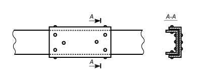
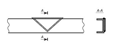
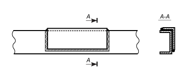
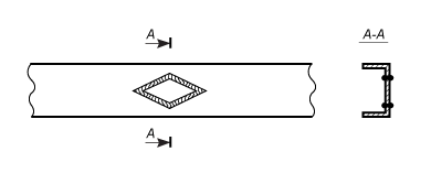
Cracks are repaired by welding and riveting of reinforcing linings.
The main feature in preparation for welding:
- determination of the visible end of the crack (using a magnifying glass);
- drilling the end of the crack (before drilling, turn the center under the hole at a distance of 5 - 10 mm from the visible border of the crack along the line of its direction; drill with a drill with a diameter of 5-6 mm);
- cutting edges at a bend of 90 degrees to a depth of 2/3 of the thickness of the metal of the part, with a plasma cutter, if not, you can use a grinder, but it takes longer.
- cleaning the edges of a crack with a width of 20 mm (steel brush or electric sander).
The cracks on the side members are eliminated:
- welding and installation of an external or internal reinforcing box-shaped lining on rivets;
- welding of a crack and welding of a reinforcing triangular plate;
- welding of a crack and welding of a reinforcing plate made of angle steel;
- longitudinal cracks or a bunch of cracks on the vertical wall is eliminated by cutting out the damaged area and welding a diamond-shaped insert;
Before installing the overlay, the seam must be trimmed flush with the base metal.
If it is not possible to boil the root, then it is better not to take up the welding of frames.
- First pass root boil: current 100 A wire Sv08 1.2mm gas mixture Ap + CO2 20% short rollers from left to right across the crack with interruption of the arc and without overheating the metal, but with the formation of a reverse roller.
- Second and third pass current 110 A exactly the same, but the rollers should be thin and overlap.
- Fourth pass current 120 A a roller in the entire width of the groove with a slight approach to the base metal, the rollers are dense and, depending on the heat loss, it can be a continuous seam, but without overheating the metal (3-5 rollers and interruption of the arc).
- The fifth roller overlaps in each direction the minimum is cooked in the same way, but without interrupting the arc. The seam is wide, convex, and quite even.
The vertical is cooked only from top to bottom. If the client asks to hide the traces of welding, then the fifth roller is not cooked.
Each case of frame welding is very individual.
Large seams should not be cooked at a time, since in the heat-affected zone the metal will harden and become brittle when deformed.
In the photo, the frame has already been made, the seam is disgusting. I had to redo it.
Seams were cut at 90 degrees, where VIN was, holes had to be drilled, this in order to relieve stress, so part of the crack cannot be welded, and if you do not make holes, then from metal stress, the crack will go back to welding.
The seams were welded using the technology above.
In the repair that is provided above, the pad was not required. An extra weld seam is not good for the structure. The pads are used in case you need to strengthen the frame, where the metal is tired, and there are many vertical cracks. It is better to weld diamond or elliptical overlays rather than overlapping.
For linings and patches, you need to take the same steel from which the frame is made.
here is my branch where I repaired the frame.
my car is running on a daily basis now.
everything works well there are no comments on the repair of the frame.
It's a good idea to wrap the old frame with a new one that fits.
you still need to start such a repair with sandblasting
god help.
Fig-behold, what frame should you pay attention to? Which one is closer to “us” or which is all in rhombuses? How does Kyzya miss such a thing?
Fig-behold, what frame should you pay attention to? Which one is closer to “us” or which is all in rhombuses? How does Kyzya miss such a thing?
Yes, about ZIL, I'm also interested?
the one that is closer, I sold them a half-cut, they will splicate it with their tail (by the way, it is from zil).
and here are the last photos of my zilka
[QUOTE = Dzenz; 1151760895] The frame broke on both sides. Broken at the attachment point of the rear ladders. I was looking for something similar on the forum did not find it.
Looking for advice on how BEST to brew?
Can someone help with a material?
I would be grateful for any useful advice.
The frame of Ural cars of the spar type consists of two spars, which are interconnected by six crossbars and a front bumper.
The frame side members are forged, made of variable profile sheet steel, reinforced in the middle and rear. Towing hooks are installed at the front of the frame for towing the vehicle. In the rear part of the frame, a towing device is installed in the cross member, equipped with a double-acting spring, which softens the shock loads on the frame when driving with a trailer.
The frames of the Ural-377, -375Н, -377С, -375СН vehicles have balancer brackets shortened in height, which reduce the loading height of the platform by 44 mm.
The frames of the semitrailer tractors are shortened at the rear and have two rigid tow hooks instead of a towing device. For maintenance and protection against splashing with mud, platforms are installed on the frames of truck tractors.
The chassis frame of the Ural-375A car, in contrast to the Ural-375D car frame, is lengthened by 335 mm at the rear.
Maintenance of the frame consists in checking its geometric shape, bolted and riveted connections.
The quality of the riveted joint is checked by knocking the rivets with a hammer. Loose rivets should be replaced with new ones or bolts and nuts.When repairing a rivet joint in case of worn rivet holes (more than 15 ° / o / nominal diameter), weld the holes and drill new ones after marking.
Deflections and distortions of the frame are determined by inspection, as well as by checking using rulers and templates.
The geometric design of the frame is checked by measuring it up to the diagonal in separate sections. The difference between each two diagonal dimensions of the same name (B, C, D, D, E) should not exceed 5 mm.
The difference in the width of the front and rear ends of the frame should be no more than 4 mm.
Edit the frame when cold.
Maintenance of the towing device consists in lubricating and cleaning it from dirt, tightening the bolts securing the cross member of the towing device to the frame, in checking the lateral clearance of the hook in the guide bushings. The towing hook nut must be tightened to a position that prevents axial movement of the hook. In this case, the hook should rotate freely by hand.
Rice. 1. Frame:
1 - front buffer; 2 - towing hooks; 3 — right spar; 4 - the first cross member; 5 - bracket for the cab and shock absorber; 6 - amplifiers of spars; 7 - cross member of the additional transmission support; 8 - cabin bracket; 9 - second cross member; 10 - third cross member; 11 - fourth cross member; 12 — fifth cross-piece; 13 - sixth cross member; 14 - back buffers; 15 - cross member of the towing device; 16 - balancer bracket; 17 - rear bracket of the front spring; 18 - left spar; 19 - front bracket of a front spring
Rice. 2. Towing device:
1 - nut; 2 - washer; 3 — cross member of the towing device; 4 — sleeve; 5 - spring; 6 - the cross member of the towing hook; 7 - bolt; 8 - latch dog; 9 - the axis of the dog; 10 - latch; 11 - chain; 12 - finger; 13 - towing hook; 14 - reinforcing plate
Rice. 3. Checking the geometry of the frame
Depending on the quality of welding work, the repair of the side members is a measure that ensures the vehicle's mileage before replacing the repaired frame with a new one. If cracks are found in the frame side members, carry out the following work.
At the end of the crack, drill a through hole with a diameter of 3-5 mm. Cut a groove for welding along the entire length of the crack on both sides of the spar section to a depth of 4 mm at an angle of 90 °. Apply the weld seam from the drilled hole to the end of the crack. Smoothen the seam on the inner side of the longitudinal member until the reinforcing strip fits snugly. On the inner side of the welded crack, install a reinforcing plate with a channel section, symmetrically positioning it relative to the crack. Only weld reinforcement plates with longitudinal seams. The material of the reinforcing linings is a 6-8 mm thick mild steel sheet.
Rice. 4. Place of installation of reinforcing pads when repairing cross member No. 2:
1 — possible places of cracks; 2 - reinforcing strip
On cars manufactured before 1972, the upper and lower parts of cross member No. 2 were connected with rivets. If a crack is found on the bottom sheet of cross member No. 2, it is necessary to drill a hole with a diameter of 3-5 mm at the end of the crack and install a bolt-on pad. For attaching the linings, you can use the existing rivet holes or drill additional holes Ø 11 mm for bolts Ø 10 mm.
The material of the lining is a 5–8 mm thick sheet of mild steel.
If cracks are found on the shoes of cross member No. 2, passing through the extreme rivets of attachment to the side member, it is necessary to cut down eight extreme rivets and drill through holes 0 15 mm at a distance of 50 mm from the cut rivets. Drill the end of the cracks on the shoes with 0 3-5 mm, weld the cracks. Fasten the cross member to the side members through reinforcing pads with M14X 1.5X40 bolts, M14X 1.5X11 nuts, 14.2X23.2X4.5 washers. The material of the reinforcing lining can be a steel sheet 5-8 mm thick. The approximate dimensions of the lining are 90X32.
Rice. 5. Places of installation of reinforcing pads when repairing shoes of cross member No. 2:
1 - possible cracks in the shoe; 2 - reinforcing strip
When repairing frame side members and cross member No. 2, it is recommended to use electrodes of the E42A, E46A, E50A types with a rod diameter of 3 to 5 mm. After repairs, paint the frame.
One of the characteristic signs indicating the need to disassemble and adjust the gearbox is increased noise when the vehicle is moving. Causes of increased noise:
- displacement of the contact patch in the engagement of the bevel gears as a result of a violation of the adjustment of the tapered bearings;
- seizure and chipping of gear teeth, wear of bearings, as well as insufficient oil level in the axle housing.
attachment and roll the cart out from under the car.
The procedure for dismantling the middle (rear) drive axle is as follows.
Place the vehicle on the inspection ditch. Close the wheel cranes (only for Ural-4320 and 4420).
Loosen the nuts securing the wheels of the axle to be dismantled, remove the protective covers and disconnect the air supply hoses from the wheel valves.
Drain the lubricant from the axle housing.
Raise the rear of the vehicle and place a stand under the rear end of the frame. Unscrew the wheel nuts and remove the wheels. Install and fix the device (fig. 1).
Using the adjusting eccentrics, spread the brake pads, thereby preventing the axle beam from turning during subsequent disassembly operations.
Remove the propeller shaft of the middle (rear) axle drive, disconnect the hoses and lines of the brakes, the sealing system (only for Ural-4320 and 4420), and the tire inflation system.
Disconnect the upper torque rod bracket from the axle beam, disconnect and remove the lower torque rods.
Roll the assembly trolley under the bridge and, after removing the complete bridge beam, lower it onto the trolley using the tool.
Disconnect the tool and roll out the cart with the driving middle (rear) axle from under the vehicle.
When removing the front axle, carry out preparatory work similar to those described above. Additionally, it is necessary to disconnect the steering linkage bipod from the left steering knuckle lever, the hydraulic booster from the right steering knuckle lever.
Disconnect and remove the lower shock absorber heads from the brackets.
Using the installed and fixed device, raise the axle and, by unscrewing the nuts of the ladders, remove the clamps for securing the front springs.
Lower the front drive axle onto the bogie.
The gearbox of the front axle, unlike the gearbox of the middle (rear) axle, must be dismantled only after the axle assembly has been removed from the vehicle.
Place the dismantled front axle on the stands. Disconnect steering linkage, brake hoses and sealing systems.
Unscrew the nuts securing the ball joints.
Using a spudger, remove the knuckle assemblies using the grooves in the ball joint flanges.
Remove the side cover 35 (see Fig. 2) of the gear case assembly with the oil inlet connection 25 and unscrew the bolts and nuts securing the gear case, including two bolts located inside the crankcase.
Using a lifting device, remove the gearbox from the axle housing.
Medium (rear) axle reducer using a tool to dismantle directly from the vehicle installed on the inspection ditch, to do this, close the wheel valves, remove the protective covers and disconnect the air supply hoses from the wheel valves.
Drain the lubricant from the axle housing. Unscrew the bolts securing the hub caps, unscrew the air supply brackets from the axle shafts and remove the hub caps together with the seals and air supply hoses. Then, using a puller, remove the axle shafts.
The range of work performed and their complexity. Dismantling of the Ural-4320 car into units. Repair technological process. Rational sequence of operations. Calculation of the main equipment. Calculation of the need for energy resources.
Students, graduate students, young scientists who use the knowledge base in their studies and work will be very grateful to you.
Posted on
Labor productivity, cost reduction and improvement in the quality of road car repairs largely depend on the organizational methods of overhaul of cars. In the repair industry, there are individual, nodal and flow methods of overhaul. The choice of the method depends on the number, design features and uniformity of machines, as well as on the technical equipment of the repair company.
Considering that the growth of labor productivity depends on the level of mechanization and automation of production processes, therefore, one of the main tasks is to equip each workplace, post with a set of technological equipment, tools and devices as much as possible.
Of great importance for increasing labor productivity during maintenance and repair, and ensuring their quality, is the widespread introduction of the scientific organization of labor (NOT) in production. The latter includes a large range of measures, including improving the organization and maintenance of workplaces, improving the techniques, methods and regulation of labor, creating favorable sanitary, hygienic and aesthetic working conditions, etc.
The purpose of my course project is to design a department for disassembling machines into units of a department.
The objectives of the project are to calculate the frequency of maintenance; determination: the number of services per year, the technical readiness coefficient, the daily program of cars; distribution of labor intensity for maintenance and repair of vehicles and self-service of the enterprise; distribution of work intensity; calculation of the number of workers; selection of technological equipment; department layout, etc.
Projected department disassembly of cars into units at a car repair plant is intended for disassembly of a URAL-4320 vehicle into units in order to send them to their departments for repairs.
This department is part of the disassembly and assembly workshop. It is planned to organize the technological process of disassembling machines into units.
- Organization of workers' labor, clarity of production management (whether there is a loss of working time, analyze why);
- Compliance with labor discipline at the facility;
- The need to replace outdated technological equipment;
- Availability of a sufficient area of the department (zone) to carry out the scope of work;
- Necessity and possibility of mechanization of labor-intensive work, exclusion of manual labor;
- Compliance of the existing arrangement of equipment with the requirements of the scientific organization of labor;
- Requirements for the state of ventilation, lighting, fire extinguishing equipment;
- Availability of the necessary documentation (technological maps, etc.).
Ural-4320 - double cross-country truckwith a wheel arrangement of 6 Ch6, manufactured at the Ural Automobile Plant in Miass (Russia), including for use in the armed forces in the family of unified army vehicles "Susha" until 1998.
The Ural-4320 was designed to transport goods, people and trailers on all types of roads. It has significant advantages over similar vehicles: it easily overcomes swampy areas, fords up to 1.5 m, ditches up to 2 m, ditches, rises up to 60 ‰. For 1986, more than a million trucks were produced. Today the Ural is produced with a diesel 230/300 hp engine (Euro-2).
Initially, the Ural-4320 was equipped with a KamAZ-740 engine, but as a result of a fire at the KamAZ engine plant in 1993, the deliveries of this engine stopped, and the YaMZ-236 and YaMZ-238 engines of the Yaroslavl Motor Plant began to be used. Initially, modifications with a YaMZ-238 engine differed in their outwardly longer engine compartment, and cars with a YaMZ-236 engine retained the same engine compartment as in cars with a KAMAZ-740 engine (the difference is that cars with YaMZ-236 have an air filter on right wing). Since the mid-2000s, all cars, regardless of engine model, have been produced with an extended engine compartment.
Since the mid-1990s, a wide bumper with headlights has appeared on the Ural-4320 and Ural-5557, and plastic plugs have appeared in the wings, at the old headlight attachment points. However, exclusively for the needs of the Ministry of Defense, by special order, until now [when?] Cars with narrow bumpers and headlights in the fenders are being delivered.
Since 2009, a new cab with fiberglass front empennage has been installed on cars of the series.
12-14 t with low-profile wide tires with adjustable wheel inflation, which significantly increases the vehicle's permeability;
The works are carried out on the basis of LLC TPK "Ural-MAIR" in the city of Miass. The company is engaged in the implementation of the following work to improve and optimize the Ural vehicle.
- removal of the muffler forward;
- shielding of electrical wiring;
- reinforcement of the walls of the gas tank of the car with side and bottom-side protection;
- installation of flashing beacons on the machine.
- External trigger socket;
- OV-95;
- OV-65;
- planar 3.5 kW;
- O-31 (5 kW);
- installation of an electric pre-heater from 220 volts.
- installation of a special subframe under the saddle;
- heating of fuel lines;
- heat supply for heating filters FTO, FGO;
- insulation and heating of the battery;
- heated all seats in the car;
- heated mirrors;
- removal of the muffler system,
- insulation of the cabin with penofol;
- installation of double-glazed cabins;
- interior / cabin insulation with felt;
- sale of insulated seat covers.
- installation of a rear underrun protection device;
- removal of the muffler up;
- insulation of the cabin / cabin with a sleeping bag with penofol;
- heating the fuel intake;
- installation of a lower trailing system;
- revision, lengthening and strengthening of the frame;
- installation of an additional fuel tank (200, 300 or 500 liters).
You can find a complete list of types of improvements and prices for them in price list.
-Repair of URALA-4320 driving axles.
-Repair of the transfer case.
Ural vehicles (6x6) with diesel engines YaMZ-236M2 and YaMZ-
238M2 JSC "Avtodiesel" Yaroslavl, three-seat all-metal cab,
located behind the engine, designed to transport goods, people and
towing trailers on all types of roads and terrain. Basic models
are multipurpose vehicles Ural-4320-10 (Fig. 1) and Ural-
4320-31 (Fig. 2), created by modernizing the Ural-4320 vehicle, where the hyphens
- 10 and 31 (30) show the engine model (YaMZ-236M2 or YaMZ-238M2
respectively) installed on the vehicle.
Ural-4320-10 and Ural-4320-31 vehicles comply with the TU requirements
37.165.223-93 “Ural-4320-10 multi-purpose vehicle and its
modifications ", TU 37.165.246-94" Car Ural-4320-31 multipurpose
purpose and its modification ”.
Resource before the first overhaul under the first category of conditions
operation in accordance with the “Regulation on maintenance and
repair of rolling stock of road transport ”, subject to compliance
of all the rules specified in the operating manual must not be less than:
- for cars Ural-4320-10, Ural-4320-31 and their modifications
- for the Ural-44202-0311-31 car - 200,000 km.
During the specified period, replacement of components and assemblies is allowed,
passed the established mileage, as well as purchased products, the resource of which,
established by the technical documentation of the supplier enterprises and
standards, less vehicle resource.
The service life of the product is 10 years, not less.
Ural vehicles are designed to operate at temperatures
ambient air in the range from plus 50 to minus 45 ° С (short-term
On the basis of Ural-4320-31 and Ural-4320-10 vehicles are produced
- Ural-43202-0351-31 vehicle for general transport purposes with
- truck tractors Ural-4420-10 and Ural-4420-31 are designed for
towing special semi-trailers on all types of roads and terrain;
- the Ural-44202-0311-31 truck tractor is designed for towing
semitrailers on all types of roads;
- the Ural-44202-0612-30 truck tractor is designed for towing
semitrailers on airfields and flat areas;
- car Ural-4320-0911-30 with an increased base is designed for
transportation of goods and people on all types of roads and terrain;
- cars Ural-4320-0611-10 and Ural-4320-0611-31 with wooden
platform and awning are designed for the carriage of goods.
1.Acquaintance with the enterprise. (Federal State Unitary Enterprise of the Ministry of Defense of the Russian Federation. Veliky Novgorod. Pankovka settlement) Passed safety instructions (Appendix 1). Was assigned to repair the Ural car.
Repair of leading bridges URALA-4320,
Drive axles of the vehicle through passage type, with the upper arrangement
The main gear of the axle is double, consists of a pair of bevel gears 1 and
14 (Fig. 39) with helical teeth and a pair of cylindrical gears 4 and 32 with helical teeth. A symmetrical bevel differential with four satellites is bolted to the driven spur gear.
Depending on the technical requirements for the car, the main gears
have gear ratios of 7.32; 6.7; 8.9 and 8.05
1-bevel driven gear; 2,23-cylindrical roller bearings; 3-
main gear case; 4-pinion cylindrical driving; 5-glass of bearings;
6-tapered roller bearing; 7,8,12-adjusting gaskets; 9-cover
bearing cups; 10-flange of the middle axle drive; 11-cuff; 13-glass
bearings of the leading bevel gear; 14-bevel drive gear; 15-
breather; 16-shaft of the driving gear; 17-gasket; 18-flange of the rear axle drive;
19-flange nut; 20-rear bearing cover; 21-spacer sleeve; 22-cover
front bearing; 24-adjusting washer; 25-nut; 26-lock washer; 27-
lock washer; 28-lock nut; 29-semi-axial gear; 30-satellite differential;
31-differential crosspiece; 32-gear driven cylindrical; 33-washer
support; 34-differential bearing cover; 35-plate locking; 36-plate
lock; 37-nut adjusting differential bearing; 38-cup
differential; 39-crankcase cover; I-for the front axle; II-for the rear axle.
The main gears of the front and rear axles differ from the main one.
transmission of the middle axle with drive flanges.
The middle (rear) leading axle (Figure 4):
1-cuffs for air supply; 2-cylinder wheel; 3-drum brake; 4-semiaxis;
5-spring support bracket; 6-crankcase cover; 7,9-gaskets; 8-gear main;
10-axle housing; 11-drain plug; 12-plug control; 13-axle shaft casing.
Front axle car leading, controlled.
the moment to the front driving wheels is transmitted through the axle shafts and joints of equal angular velocities.
Drive to the steered wheels of the front driving axle (Fig. 5):
1-hose for air supply; 2-lock washer; 3-lock washer; 4-lock nut;
5-wheel bearing nut; 6-pin; 7-sided air inlet; 8-cover
wheel hubs; 9-semiaxis outer; 10-block of cuffs; 11,17,19-gaskets
sealing; 12-bearing; 13-hub; 14-cylinder wheel brake; 15-
brake drum; 16-caliper brake; 18-ball support; 20-semiaxis, internal;
21-axle shaft casing; 22-fist hinge; 23-disc hinge; 24-plug male
half shafts; 25-pin; 26-reflector; 27-cuff.
.When repairing drive axles oils are used
according to the map of lubricants and working fluids, and further maintain the required level in the crankcases. To replace the lubricant in the front axle half-axle hinges, remove the wheel, brake drum with hub, caliper, pivot pin. We remove the grease and wash the parts of the constant velocity joint.
If it is necessary to dismantle the ball joint from the front axle housing
use puller bolts. To do this, we install them in the threaded holes of the ball joint flange and, turning them evenly, remove the tail of the ball joint from engagement with the axle shaft casing.
The constant velocity joint (Fig. 6):
1-plug; 2-fist; 3-disc; 4-semiaxis internal.
Adjust the final drive in the following sequence:
1. Install the main gear in the device, remove the differential
and flanges.Remove the bolts securing the bearing cup of the drive bevel gear. Take out the pinion shaft with a glass and a pinion. Place the pinion gear in a vise, gripping it by the ring gear. Unscrew the bolts securing the cover and remove it. Unlock the lock nut and turn it off. Remove the lock and lock washers. Tighten the nut with a torque of 50-500 N.m (45-50 kgf.m).
Install the indicator fixture and determine the gap in the
briars. If there is no gap after tightening the nut, adjust
cup bearings are required.
Calculate the amount of reduction in the thickness of the shim 24
(see Figure 3) (clearance plus 0.03-0.05 mm of preload).
Unscrew the nut, remove the bearing and shim. Grind (or select) the washer to the required size, install the washer and assemble the bearing assembly of the drive bevel gear. The tightening torque of the nuts is 450-500 N.m (45-50 kgf.m). Lock the locknut by bending the washer to one of its edges. The torque required to turn the leading bevel gear in the bearings should be 0.6-1.4 N.m (0.06-0.14 kgf.m). Dynamometer force
when unwinding the cord from the surface of the glass - 7.5-17.5 N (0.75-1.75 kgf) (Fig. 7)
tapered drive bearings
2. Adjust the bearing preload of the drive
cylindrical gear. Adjust the bearings by selecting a package of gaskets 8 (see Figure 3) under the cover 9 of the cup 5. The torque required to turn the intermediate shaft should be 0.9-1.5 N.m (0.09-0.15 kgf.m) ...
3. Install the glass with the leading bevel gear in the main case.
noah transmission. Tighten the cup mounting bolts to a torque of 60-80 N (6-8 kgf).
Check for proper engagement of the bevel gears on the paint. Length
indentation must be at least 60% of the tooth length.
4. Install the differential and adjust the bearings of the differential
ferential. Tighten the bolts of the differential bearing caps to a torque of 250-320 N.m (25-32 kgf.m). Adjust the differential bearings with nuts 37 (see Fig. 3). After tightening the nuts, the distance between the differential bearing caps should increase by 0.04-0.14 mm. While adjusting, rotate the differential to install the rollers in the bearings. The rim of the driven spur gear must be located symmetrically relative to the rim of the driving gear.
Then, after repairing the bridge, we install it on a test stand (the stand was developed at the same plant)
The URAL 4320 has a five-speed, mechanical, three-shaft, three-way gearbox with two inertial synchronizers. The first reverse gear is shifted by a toothed clutch. The box is controlled mechanically with a lever.
Maintenance and repair of variable gearboxes. Includes - adjustment and lubrication of gear shifting drives, oil change and checking its level in the crankcase, checking the tightness of the pneumatic drive, replacing worn out synchronizers and gears.
8.5 liters of oil are poured into the URAL 4320 car. It is recommended to refuel with Tsp-15k automotive gear oil.
The box is tested at the stand. (The stand was developed at the same plant.)
3. Repair of the transfer case.
Transfer case (Fig. 8) mechanical, two-stage, with unbalanced
| Video (click to play). |
metric center differential, mounted on the car frame on four rubber pads. A planetary type differential with four satellites, sun 30 and 29 gears. The moment from the sun gear 30 is transmitted to the front axle drive shaft 35, and from the ring gear 29 to the rear axle drive shaft 21.

