In detail: do-it-yourself repair of the Kia Sportage 2 handout from a real master for the site my.housecope.com.
Transfer case overhaul - general information
Overhaul of the transfer case is a difficult procedure to perform on your own. It involves the disassembly and correct reassembly of many small assemblies and components. It is necessary to accurately measure the many gaps and correct them correctly by choosing the appropriate size shims and circlips. Thus, if it becomes necessary to overhaul the transfer case, its removal and installation can be performed by an amateur mechanic, while the actual repair and restoration should be left to the car service specialists. There is a possibility of purchasing remanufactured boxes - consult the specialists of the dealer department. In any case, the time and money spent on repairing and restoring the old box will be quite commensurate with the cost of purchasing a restored unit.
Nevertheless, it should be said that the overhaul of the transfer case by the forces of even an inexperienced amateur mechanic is quite possible, provided that there is an appropriate special tool and an accurate and careful approach to performing each of the procedures, when not even the smallest steps are skipped.
Tools required to perform a transfer case overhaul include pliers for removing and installing both inner and outer circlips, bearing puller, sliding hammer, drift set, plunger-type dial indicator, and possibly a hydraulic press. In addition, it is absolutely essential to have a stable, comfortable workbench equipped with a vice, or a stand for dismantling transmissions.
| Video (click to play). |
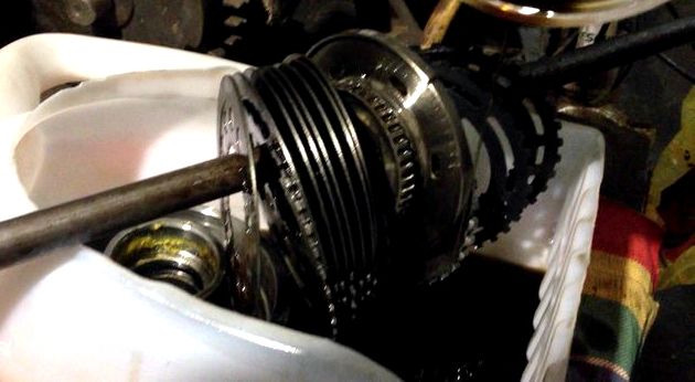
When disassembling the transfer case, pay close attention to how each of the smallest components are installed, their position in relation to other parts, and the type of fasteners (take notes as you disassemble). The accompanying illustrations provided here are intended to help you understand the layout of the box - however, drawing up explanatory notes during disassembly still much more reliably guarantees the correctness of subsequent assembly.
Transfer case components type NP231
1 - Front holder of the crosspiece, its oil seal, sealing washer and fastening nut
2 - Plug, pin and spring of the switch lock
3 - the Front holder with an oil seal
4 - the Front half of the crankcase
5 - Vacuum sensor-switch with a sealing ring
6 - Assembly of the ventilation line
7 - Bearing and retaining ring of the primary gear
8 - the Retaining ring of a gear wheel of a reduction gear
9 - the holder of the primary gear
10 - Thrust washers of a gear wheel of a reduction transfer
11 - the Primary gear wheel
12 - the Guide bearing of the primary gear
13 - the Gear wheel of the lowering transfer
14 - a hub of a fork of switching of modes
15 - the Retaining ring of the hub
16 - the Distance washer
17 - the Springs of the synchronizer
18 - Sliding keys of the synchronizer
19 - the Hub
20 - the Coupling
21 - the Blocking ring
22 - Retaining ring of the front bearing
23 - the Front bearing of a secondary shaft
24 - the Front secondary shaft
25 - the Drive sprocket
26 - Drive chain
27 - Bearings of the drive sprocket
28 - Rear bearing of a secondary shaft
29 - the Driven shaft
30 - the Epiploon
31 - Assembling the oil pump
32 - Rear bearing of a driven shaft
33 - the Lock ring
34 - Rear half of the crankcase
35 - Filling plug with a gasket
36 - Drain plug with a gasket
37 - the Back holder
38 - Extension casing
39 - the Bushing
40 - the Epiploon
41 - the Mesh screen of the oil sampling tube
42 - Nipple connection of a tube
43 - Oil intake pipe
44 - the Sealing ring of the oil sampling tube
45 - Magnet
46 - Nut and washer of the lever of modes
47 - the Lever of modes
48 - the O-ring and the bushing of the holder of the selector
49 - Selector
50 - Fork modes
51 - Range plug
52 - Spring modes
Transfer case components, type NP242
1 - the holder of the front bearing with an epiploon
2 - the front half of the crankcase
3 - Switching selector
4 - a Fork of switching to a lower gear with inserts
5 - the Shift rod
6 - the Shifting bracket
7 - the Slider bracket
8 - the Bushing with a spring
9 - Fork of modes with inserts
10 - Bushing
11 - the spring of a fork
12 - the Bushing
13 - Assembly of the ventilation line
14 - Bearing and retaining ring of the primary gear
15 - Retaining ring of a gear wheel of a reduction gear
16 - the Holder of a gear wheel of a reduction transfer
17 - the Thrust washer of the gear wheel of the underdrive
18 - the Primary gear wheel
19 - the Rear half of the crankcase
20 - Drain and filler plug
21 - the Rear bearing holder
22 - Extension casing
23 - the Bushing and the epiploon
24 - the Vacuum sensor-switch
25 - Magnet
26 - the Thrust ring
27 - the Lock ring
28 - the switching clutch
29 - the Gear wheel of the lowering transfer
30 - Guide bearing (primary gear / driven shaft)
31 - Front bearing of the front output shaft and circlip
32 - Shaft of intermediate clutch
33 - the switching clutch
34 - the Lock ring
35 - the Driven shaft
36 - Assembling the differential
37 - the O-ring of a tube of the oil pump
38 - Oil intake pipe of the oil pump with a mesh screen
39 - Rollers of the bearing of the driven shaft
40 - the Drive sprocket
41 - Drive chain
42 - the Lock ring
43 - the Oil pump seal
44 - the Oil pump
45 - Rear bearing with a circlip
46 - Rear bearing of the front output shaft
47 - the Lock ring
48 - Driven sprocket
49 - the Front secondary shaft
50 - Spacer washers of the driven shaft bearing
51 - Washer and nut of the shift lever
52 - the Lever of switching
53 - O-ring and sector oil seal
54 - Cork, spring and retainer pin
55 - the Sealing plug
56 - The front holder of the cross with a nut and a sealing washer, a slider and an oil seal
Transfer case components, type NP249
1 - the Epiploon
2 - the holder of the front bearing
3 - The front bearing of the driven shaft with a locating ring
4 - Front half of the crankcase (with a toothed ring of the underdrive of internal gearing and a bushing of the shift rod)
5 - the gear wheel of the lowering transfer
6 - the Primary gear wheel
7 - Thrust washers equipped with tongues
8 - Holder plate
9 - the retaining ring of the primary gear
10 - the clutch
11 - Clutch shaft
12 - the locking ring of the differential
13 - Differential assembly
14 - the Driving gear wheel of the driven shaft
15 - Retaining ring of a driving gear
16 - the Spacer washer of the driven shaft bearing
17 - Needle bearings of the driven shaft
18 - the Spacer washer of the driven shaft bearing
19 - the Driven shaft
20 - Viscous clutch
21 - the Retaining ring of the viscous clutch
22 - the Retaining ring of the oil pump installation
23 - the Oil pump
24 - Rear bearing of a driven shaft
25 - Retaining ring of the rear bearing
26 - the Drive gear wheel of the speedometer
27 - Assembling the rear holder (with a cap, an oil seal, a bushing, an access cover and a gasket)
28 - a locating ring of the rear bearing
29 - the Front half of the crankcase
30 - Rear bearing of the front output shaft
31 - Assembling the oil suction tube (with connecting hoses, mesh screen, tubes and O-ring)
32 - Assembling the shift fork with the rod (including fork lining)
33 - Drive chain
34 - the Front secondary shaft
35 - the Switching selector
36 - the crankcase magnet
37 - Front bearing of the front output shaft
38 - Retaining ring of the bearing
39 - Plunger and retainer spring
40 - Plug and retainer O-ring
41 - Lock nut and washer of the mode lever
42 - the Lever of modes
43 - Oil seal (front bearing of the front output shaft)
44 - the Holder of the secondary shaft cross
45 - the Sealing washer of the holder of the cross
46 - the Nut of the holder of the cross
Before sending the transfer case for repair, it is useful to have an idea of which part of the transfer case is malfunctioning. Some of the defects are uniquely associated with different nodes, which can greatly simplify the troubleshooting procedure and reduce the time for troubleshooting. See also Section Troubleshooting at the beginning of the Guide.
Many owners of Kia Sportage and Kia Sorento, Hyundai Santa Fe and Hyundai IX35 / Tucson, especially after 2009 release (the so-called third generation), are faced with four-wheel drive problems, which often sounds like this:
- I got under way, I had to accelerate, I pressed the gas, received a strong blow;
- when driving, I heard a blow in the area of \ u200b \ u200bthe driver's legs / armrest on the bottom. At the same time, the car continues to move, as if nothing had happened;
- a couple of times I put it in the mud on my belly (they pulled it out with a tractor), after a while the four-wheel drive disappeared;
- four-wheel drive does not turn on / refused;
- pulled / towed another car, after that the all-wheel drive error lights up;
- does not turn the rear universal joint.
As a rule, this problem manifests itself in winter, also when passing through mud pits (when the car owner discovers that the front wheels are "whistling"). If you drive only on asphalt roads, do not start abruptly at traffic lights, then you may not notice anything, but the problem, obviously, will not disappear by itself.
In the overwhelming majority of cases, the cause of the malfunction is in the splined connection between the transfer case (transfer case) and the gearbox. The slots are simply ripped off (licked off). Diesel cars are no longer lucky, in which the torque is greater than in gasoline ones.
This is a real disease Kia Sorento, Kia Sportage, Hyundai SantaFe, Hyundai Tucson (IX35) after 2009. Moreover, sooner or later, almost every owner of these cars is faced with this, if you do not do preventive maintenance (for example, you can read the link, although according to reviews this does not always help).
The initial diagnostics is simple: the car on the lift, turn on the gear and look at the rear universal joint, if it does not spin, then most likely you have a breakdown of the transfer case, which we are writing about. If the cardan is spinning on the lift, then most likely the problem is in the all-wheel drive clutch. We also add that we strongly do not recommend driving for a long time with such an all-wheel drive malfunction, since overheating from friction of the transfer case mechanisms can cause additional damage to the transfer case.
In different sources (for example, ref. 1, ref. 2, ref. 3, ref. 4, ref. 5), the root cause is an oil seal (OE-number: 47352-39300), which is located at the input of the intermediate shaft of the right axle shaft into the transfer case. A defective oil seal will cause moisture and dirt to enter the dispenser. All this (since the washer passes through the transfer case) comes to the splined connection of the transfer case shaft and the gearbox differential cup (in another way: the differential case, the differential cover-cover). Over time, under the influence of corrosion, the metal weakens and cuts the splines.
If you look at the part of the washdown in the distributor box, then there is a lot of rust, which confirms the correctness of this judgment.
The solution to this problem, frankly, is not cheap. If you are lucky and cut the splines only on the distributor, then such a repair with the work of a master and the purchase of a used distributor can cost from 450 dollars. It's scary to even talk about buying a new handout, taking into account its price.
If you are unlucky and also cut off the slots of the case (cup) of the differential, then you need to buy it too, which can additionally cost 100-400 dollars. (depending on modification)
We offer a cheaper option and no less reliable - restoration of transfer case splines and / or differential housing. It will cost at least half the price.
TECHNOLOGY OF PERFORMANCE OF WORKS ON REPLACEMENT OF AUTOMATIC COUPLINGS FOR A / M KIA SPORTAGE
(from Mike482 aka Mikhail Chernyshev & Kostas aka Konstantin Lysakov)
Consumables: Grease (recommended with molybdenum), gasket sealant.
Replacement Parts: You may need everything from bolts and washers to the complete coupling.
Note: All English part names and part numbers are taken from the spare parts catalog from the site:

Using a 10 key, unscrew 6 bolts "BOLT 0K01133206A" fastening the outer part of the "FREE WHEEL HUB-AUTO 0K01A3320XA" coupling (Fig. 1)
Removing the crown ring from the outer part of the sleeve (Fig. 2).
Typical malfunctions: Broken antennae, wear of the plastic sleeve of the coupling and squeezing of the back of the crown ring (Fig. 3 and 4, respectively).
Rice. 3. Breaking of antennae and wear of the clip.
Rice. 5. Remove the counterpart of the coupling (FIXED CAM 0K01A33040, it is also the counterpart, it is the hub of the coupling). General view is shown in Fig. 6.
The second way to pull out the lock washer: we take a 2mm aluminum wire and wind it around the lock ring around the SHRUS slots so as not to let the ring sit back into the groove, which it constantly strives to do. Then we take it out with our hands.
After removing the lock washer, take out the regular washer. After that, gently prying the counterpart from different sides with a screwdriver, pull it out.
Typical malfunctions: Squeezing antennae, breaking off the legs (Fig. 8 and 9).
Disassembly is complete. All parts are recommended to be cleaned of old grease, rinsed and lubricated from the heart.
Assembly: We take the otvetka, put it on the CV joint and carefully insert the 2 protruding legs into the grooves intended for them. The otvetka is put in tightness, so gently tap it in a circle with a hammer through a piece of wood until it snaps into place. We put on the washer, then the lock washer, until it fits into the groove of the CV joint.
Lubricate the joint with sealant and put the outer part of the coupling in place so that the protruding teeth fit into the corresponding grooves on the counterpart (Fig. 10).
1.if it is possible to hang out the entire front end:
When 2WD is turned on, the front universal joint rotates by hand, and one of the front wheels is held by hand. In this case, the other wheel must rotate. If the wheel does not spin in such layouts, then the overrunning clutch (or its component) is a polar fox (arctic fox).
2.check in garage conditions:
Jack up 1 front wheel. In 2WD mode, the front universal joint rotates by hand, the wheel should rotate. We try to hold it with our hand - it should spin (as far as the strength is enough to turn the cardan). If it does not spin, then the sleeve is a polar fox. Likewise the second wheel. In the same way, it is a good idea to check if the clutch disengages. First, turn on the clutch by rotating the universal joint. Then we turn the wheel in the same direction, while the cardan is already spinning, driven from the wheel. And then we turn the wheel in reverse (we simulate a rollback). Light click, the gimbal stops.
3. Check from American colleagues:
“Sorry, but I have to jump in here. The Sportage does not have a center differential of any type. It uses a mechanical U joint to connect the front and rear axles to the drive train. If you run in 4WD on dry pavement you may (and probably will) snap it. Make no mistake about it!
You can test it. Put it in 4WD, release the brake and move forward 1 or 2 MPH. Then turn the wheel. You will notice a high resistance in the steering to the point you will think you have no power steering. This is the pressure buildup (or binding) - difference in the front and rear axle rotation. That pressure builds right smack in the middle where the U joint is.
There are no clutches or lubricant to release this pressure! "
Translation from Kostasa (I translate freely and briefly) On a dry flat surface, turn on 4WD and drive slowly. Turn the steering wheel and you will feel a lot of effort on the steering wheel, as if there is no power steering. This is due to the difference in the rotational speeds of the front and rear axles (due to the absence of center differential).
First gear, four-wheel drive, head out the window, harder on the gas and watch the front wheel slip.
Watch an interesting video on this topic


