In detail: do-it-yourself repair of the Nokia phone charging connector from a real master for the site my.housecope.com.
You can of course throw it out and buy a new NOKIA, especially since this mobile phone has worked for almost three years, but still a 2-megapixel camera, a high-quality display and excellent sound on MP3 deserve attention.
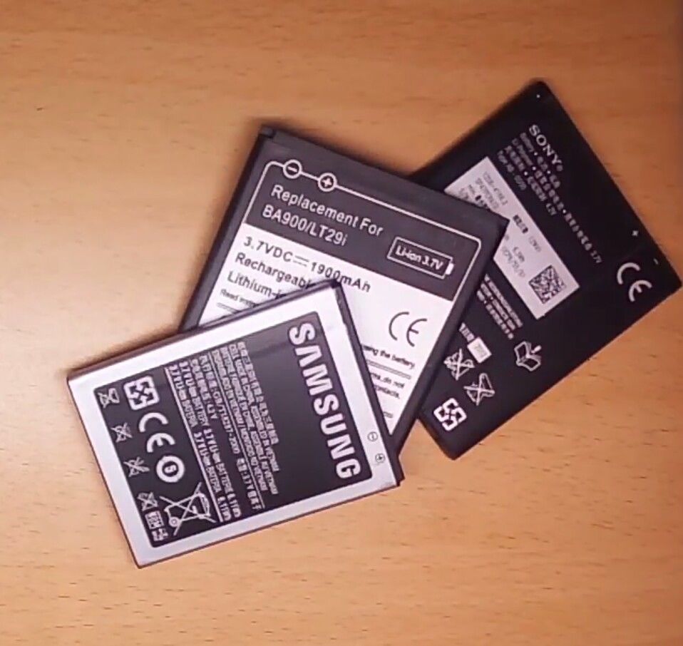
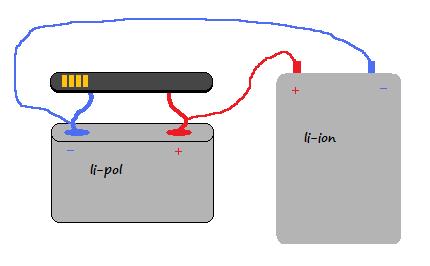
This problem - the impossibility of a normal start when turned on, is often eliminated by flashing the mobile phone. But let's not rush things and start from the very beginning - with a lithium-ion battery. The voltage measurement showed only 2.9 volts. Did I really sit down while I was carrying him home? The cell phone seemed to be freshly charged. Well, nothing, I'll connect it to my universal charger for half an hour.
Neither half an hour nor an hour later did the voltage on the battery rise above 3 volts. Even a direct connection to the power supply unit in forced mode with a charge current of 1A did not change the situation. We managed to squeeze the maximum out of the battery - 3.19V.
Now it's all clear. A mobile phone simply cannot start at such a low supply voltage. To finally make sure of this diagnosis, with the help of needles I apply a voltage of 4V from the power supply parallel to the contacts of the battery connected to the mobile phone. Voila! He lit up, lit up, earned. It turns out that the dead lithium ionic is to blame. And how often, with these symptoms, people begin to sin on the phone itself, try to reflash or take it to the workshop. In general, the conclusion is this: we start any repair with a power check.


Everybody used to face a problem when the charging socket in phones stopped working Nokia.
The reason for this is common problems like:
| Video (click to play). |
Let the charging socket (small) and not so expensive, about 10 hryvnia
50 rus. rubles. But there is not always the time and desire to run to the SC or the workshop to replace it, because the phone is always needed at hand, unless of course there is no second spare.
I found and developed a quick solution to this problem at home without spending extra money and time.
To perform this "operation" we need:
Why was a sewing needle chosen as a repair material?
Because it is rigid, does not bend, thereby providing a convenient fastening inside the nest.
How much is it?
At the cost price, it comes out 25 kopecks (1 Russian ruble) a needle and 10-15 minutes of time spent.
A visual representation on the example of Nokia 5130:
As a rule, repairing such an inexpensive device is economically unprofitable.
Especially in non-poor countries. Average price $ 5.
But it happens that there is no extra money, but there is time and spare parts.
No shop nearby. Circumstances do not allow. Then it's not about the price.
In my case, everything was simple - one of my two chargers broke Nokia AC-3E, friends brought a bag of broken chargers. Among them were a dozen branded Nokia chargers. It was a sin not to take it.
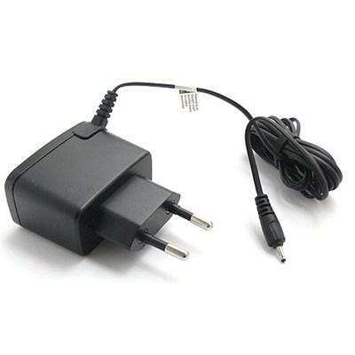
The search for a circuit did not lead to anything, so I took a similar one and remade it for AC-3E. A lot of chargers for mobile phones are made according to a similar scheme. As a rule, the difference is insignificant. Sometimes the denominations are changed, a little more or a little less elements, sometimes a charge indication is added. Basically the same thing.
Therefore, this description and diagram are useful for repairing not only AC-3E.
The repair instructions are simple and written for non-specialists.
The scheme is clickable and of good quality.
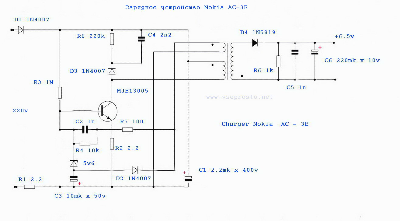
The device is a blocking generator operating in a self-oscillating mode. It is powered by a half-wave rectifier (D1, C1) with a voltage of approximately +300 V. Resistor R1, R2 limits the inrush current of the device and acts as a fuse. The blocking generator is based on a transistor MJE13005 and a pulse transformer. A necessary element of the blocking generator is a positive feedback circuit formed by winding 2 of the transformer, elements R5, R4 C2.
The 5v6 zener diode limits the voltage at the base of the MJE13005 transistor to within five volts.
Damping chain D3, C4, R6 limit voltage surges on the winding 1 of the transformer. At the moment when the transistor is turned off, these surges can exceed the supply voltage by several times, therefore, the minimum allowable voltage of the capacitor C4 and diode D3 must be at least 1 kV.
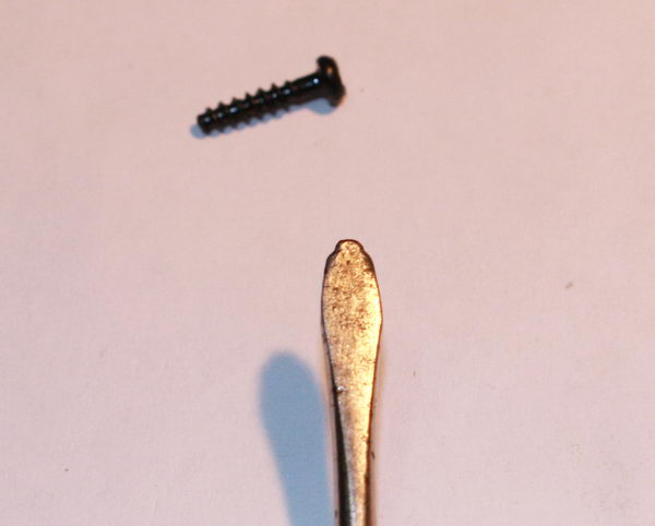
1. Disassembly. The self-tapping screws holding the charger cover in this device look like a triangular asterisk. As a rule, there is no special screwdriver at hand, so you have to get out as best you can. I unscrewed it with a screwdriver, which during the operation itself sharpened under all sorts of crosses.
Sometimes the chargers are assembled without bolts. In this case, the halves of the body are glued together. This speaks of the low cost and quality of the device. Disassembling such a memory is a little more difficult. It is necessary to crack the case with a mild screwdriver, gently pressing on the joint of the halves.
2. External examination of the board. More than 50% of defects can be detected precisely by external examination. Burnt resistors, a darkened board will show you the location of the defect. A burst case, cracks on the board will indicate that the device has been dropped. Chargers are operated in extreme conditions, so falling from everywhere is a frequent cause of failure.
Five out of a dozen memory devices that I happened to do were trite pins bent through which 220 volts are fed to the board.
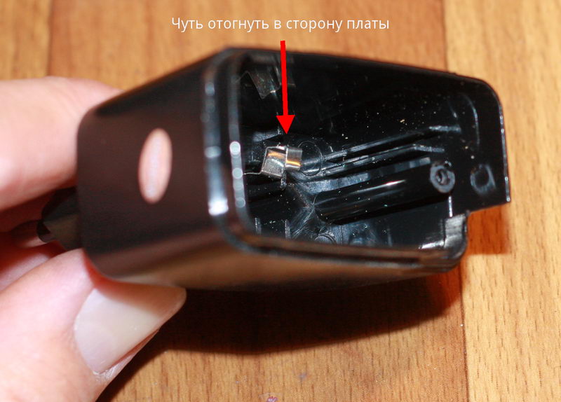
To fix it, just bend the contacts slightly towards the board.
To check whether the contacts are to blame or not, you can solder the power cord to the board, and measure the voltage at the output - the red and black wires.
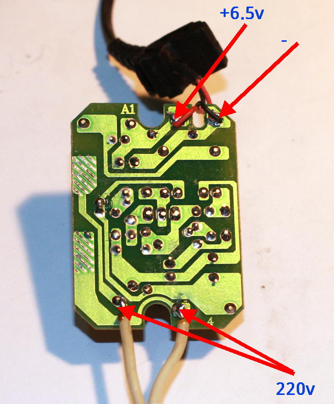
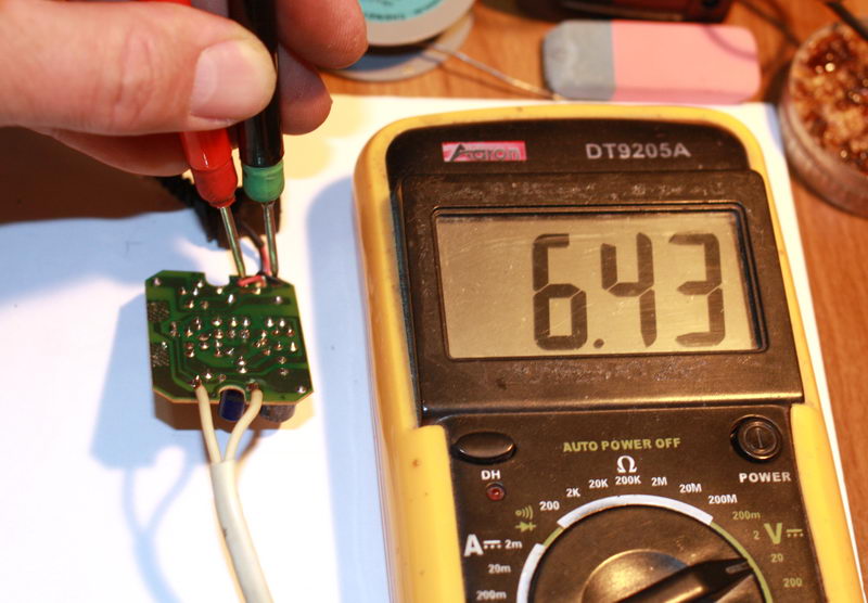
3. Broken cord at the charger outlet. It usually breaks at the plug itself or at the base of the charger. Especially for those who like to talk while charging the phone.
It is called by the device. Insert the pin of the thin part into the center of the connector and measure the resistance of the wires.
4. Transistor + resistors. If there is no visible damage, first of all, you need to evaporate the transistor and ring it. It should be borne in mind that the transistor
MJE13005 the base is on the right, but it also happens vice versa. The transistor can be of a different type, in a different case. Let's say MJE13001 looks like a Soviet kt209 with a base on the left.
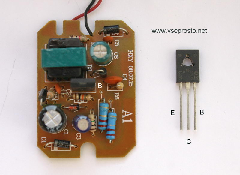
Instead, I put MJE13003. You can put a transistor from any burned out lamp - housekeeper. In them, as a rule, the filament of the bulb itself burns out, and the two high-voltage transistors remain intact.
5. Consequences of overvoltage. In the simplest case, they are expressed in a short-circuited diode D1 and a broken resistor R1. In more difficult cases, the MJE13005 transistor burns out and inflates the capacitor C1. All this is simply changed to the same or similar details.
In the last two cases, it will be necessary, in addition to replacing burned-out conductors, to check the resistors around the transistor. With the diagram, this will not be difficult to do.
Nowadays, it is hard to believe that mobile devices were the easiest way to connect with other people. Now an ordinary mobile phone has turned into a high-speed smartphone with huge multimedia functionality, and the body has begun to store the power of a good computer inside itself. The use of devices is very addictive and some do not even take a break, even for a short time. Such exploitation greatly affects charging, and constant recharging can lead to damage to one of the most important connectors of the phone. How to fix the phone charging jack if it is broken, you will learn from today's article.
How do I fix the charging port on my phone at home? Here you need to figure it out, then everything will work out. Inaccurate use of a mobile device very often ends in some kind of breakdown that needs to be fixed. Sometimes the breakdown lies in the power cable connector. In this case, you need to find out how to fix it, and for this it is worth familiarizing yourself with the main causes of the defect.
- You can spill some liquid on the device or just drop it well to disable this module.
- Constant mechanical stress deforms the socket, which can make charging the gadget simply an impossible procedure - the plug will not fit into the socket or it will dangle in it.
- Contact pads may also bend, which will completely block access to electricity.
Let's talk right away about the worst thing - about moisture.
Moisture contact of a mobile phone connector is the most dangerous damage. Corrosion will start a chain reaction and all nearby components will oxidize. Such defects can also damage the dynamics, which is most often located at the bottom of the device. Also, the speaker itself gives access to moisture to get on the cable or connector. Therefore, even light rain can damage your phone.
Important! Find out what you can do, is it possible to reanimate the gadget if a more serious trouble happened to you - the phone fell into the water and does not turn on.
The most important thing is to assess the complexity of the damage, since not all cases allow you to repair a house. The best option is to use the services of a qualified specialist from some service center. So you will not risk breaking your device.
Very rarely, restoration work can be carried out independently. It is best to find an alternative way of charging for a while, until you decide for yourself whether to fix it yourself. While the required amount is being set aside for repairs in the workshop, read the instructions for charging a phone with a broken socket:
- Insert the charger into your smartphone and plug into the network.
Important! This method is relevant only for devices that have suffered from mechanical stress, and not from moisture.
- Gently wiggle the cord and device in opposite directions. You may be able to close the contact and charge the device.
- If the mobile phone still detects the presence of a charger, then it is worth fixing the position found. Books and other items can be used that can set the phone so that the power continues.
- Before carrying out all these actions, it is worth making sure that the problem is in the socket, and not in the battery. Prolonged use of the phone leads to the fact that it no longer holds a charge. For this case, you will have to acquire a new battery, and not deal with a "phantom" breakdown.
- If it's all the same in the nest, then repairs here cannot be avoided.
Important! Remember that all these manipulations can further loosen the nest, so do not use too much force during work.
If everything is in order with the connector now, but the problem of the lack of energy in the battery still has not disappeared, read on what to do if the phone does not charge from charging.
If your phone is designed to allow you to remove the battery, then you can use the universal charger. Such devices are called "Frog". It costs, of course, not very cheap, but sometimes you need to urgently charge the phone. This gadget has special grooves into which you need to insert and fix the battery.
But this method also has a number of obvious disadvantages:
- While charging, the smartphone will not work and cannot be used until the battery is charged.
- The purchase price of "Frog" is quite high and does not always justify its purchase.
- If the reputation of the manufacturer is very dubious, then you will only harm your device.
back to content ↑
How do I fix my phone's charging connector? You can try to replenish energy reserves by disconnecting the power port itself from the phone.
Important! This method is very complex and requires the user to have basic knowledge and skills in working with equipment and electricity.
The essence of the work is as follows:
- We remove the battery from the smartphone.
- We unplug the charger from the outlet, arm ourselves with a sharp object and remove the insulation from the wire by five centimeters.
- Strip the wires and determine where the plus is and where the minus is.
- Determine the polarities on the battery and connect the wires to it.
- Secure the improvised terminals and apply mains power.
Important! This method is not recommended as you may get hurt even while charging. Do not work with uninsulated wires if you have never done so and do not know how the electric current behaves.
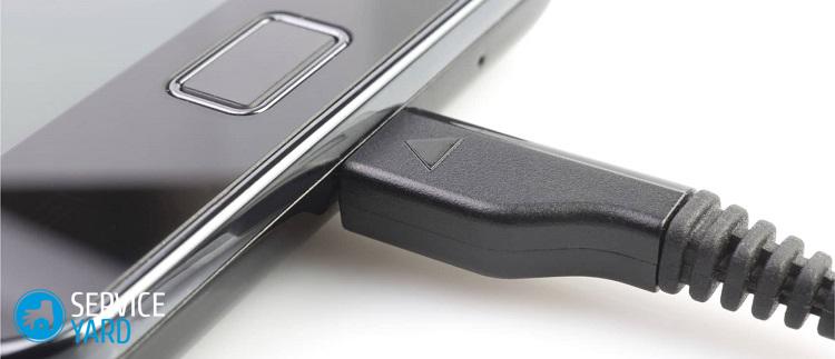
You need to be very careful if you do decide to fix the charging jack with your own hands.
To disassemble the case and remove the socket, we need:
- A small set of screwdrivers.
- Technical tweezers (regular tweezers will work as well).
- A utility knife or a regular sharp one.
- Soldering Station.
Now you need to do the following:
- We unscrew all the screws on which the case is attached.
- Carefully remove the cover by prying it off with a clerical knife.
- We ground the soldering iron, solder the wire to minus (device body). The other end of this wire must be brought to the body of the soldering iron itself.
Important! These measures are necessary so that the mobile phone does not suffer from the accumulation of static electricity, which can harm parts. It's also a good idea to make an ESD wrist strap and ground it.
- Now we unsolder all the wires from the socket. This is to prevent short circuits.
- Next, you need to remove the screws from the board that hold it. Now we have access to the microUSB connector.
- We take out the old socket, solder a new one in its place, assemble the device in the reverse order and check it for operability.
You may also find our instructions on how to clean the headphone jack on your phone useful.
The repair of the charging input on the phone is over! If you did everything correctly, then the former performance will return. We hope that henceforth you will not have to face such a problem very soon, and for this you just need to carefully handle your equipment.
It's no secret - what a miniature plug the charger for NOKIA phones has. But due to its small size, you need to be very careful with it.
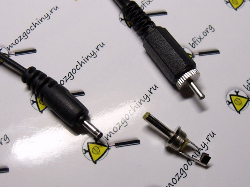

Personally, I have already broken 2 of these.)) The first one did not survive the fall from my leaky hands when the phone was on charge. After that I bought a cheap Chinese charger ($ 5), but it quickly failed, and the metal pin quickly broke off due to poor quality ... Current what to do? Buy a new one? - never!
“We need to find a connector and solder it instead of the old one” is the first reasonable thought. But the fact is that you cannot find such a plug separately! You can certainly buy an expensive universal charger with connectors for all occasions, but will we need them later?
- Syringe for 20 ml (less is unlikely to work)
- Any collapsible plug (optional)
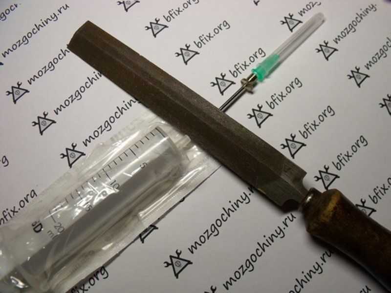
It takes 5 minutes, but it will be nice every time you charge your phone.
Step 1. Cut off the extra length of the ball needle. (Cunning: To avoid flattening the edges, apply a stress concentrator (small scratch) around the needle. After that, it will easily and evenly break off. I do not recommend sawing with a hacksaw, because the needle will bend anyway.)
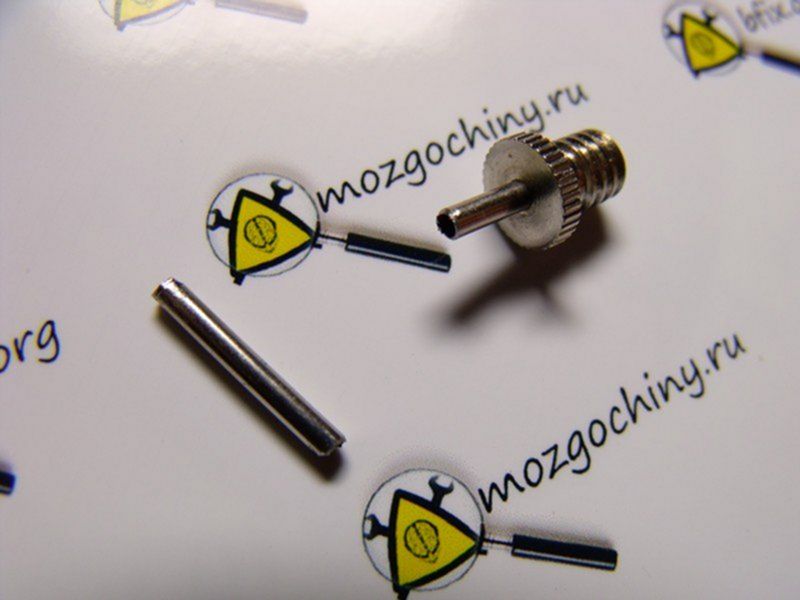
Leave 4-5 mm and work on the end of the future plug.
Step2. We also break off the future core from the syringe needle. For the convenience of soldering and protection against short circuits, I made it 25 mm long.
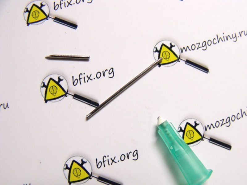
Now we isolate it with tape or a thin plastic tube and push it into the needle from the pump.
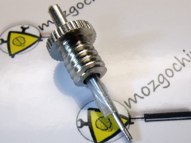
Step3. We twist. The positive red wire should be centered. Carefully soldered! You can damage the insulation if it gets too hot.
For a more aesthetic look, I put on plastic from another power plug. Ready!


Conclusion: For mere pennies, we made a good plug for Nokia phones, which is several times more durable than the original. This one will definitely survive any treatment))
- Buy homemade lightsabers from StarWars for Halloween - 09/16/2018
- How to get rid of the shortcomings of school education and the system - 09.09.2018
- Site update, registration is open again - 09/02/2018
- Find out how I make money traveling and doing what I love - 08/02/2018
- How I put my collection of 300 GB home photos and videos in order - 08/02/2018
- How to make a cool virtual reality helmet in 20 minutes v.3.0 - 07/23/2018
- Turnkey business for children - 02/09/2018
- The site administration is going on vacation! - 22.12.2017
- ATTENTION! Best Instructions Competition - 13.10.2017
- I am looking for people who want to live better, but do not know how - 09/20/2017
- Design update - 09/07/2017
- Test purchase of a kit from an inexpensive store - 03/17/2017
- Remote Assistant Vacancy - 02/14/2017
- A film about where the Brains are going - 02/05/2017
- Implementation of ideas for a questroom (we need a master in Moscow) - 09/22/2016
Hello, I have a problem: I just can't insert a needle with insulation into the needle from the pump, it's too narrow there. And the pistol is gone. Can someone tell me.
Thanks for the answer, I will take into account, but I also forgot to ask, in the connector the core is also slightly wider than in Nokia, then the needle from the syringe will fit into it, tk. the parameters of the standard plug 2.3 x 0.7 mm ?. Thanks in advance!
No problem. Pharmacies sell different syringes with different needle diameters. From droppers, for example, there are generally thick ones.
I have a tablet in my hands, whose plug broke when the tablet fell to the floor when the charger was plugged in, the plug is almost the same as that of Nokia, but slightly thicker than the needle from the ball, the plug will dangle so little in the connector that it is fraught for a tablet, can I make it a little longer and wind a piece of tape around it?
If because of this there will be bad contact, then it is not worth it. Alternatively, you can solder a little on top of the solder. Thicken the tube.
Yes, it is best to insert a wire into a syringe needle and clamp it with pliers. In my opinion, a telephone wire is ideal, of course the wires must be irradiated. Since the tape is flattened from the needle from the syringe when inserted, or the needle from the syringe dangles inside, I recommend using a glue gun for fixing. It is better to cut the needles with a dremel, if there is one, of course. It turns out almost perfect. Even for greater strength, you need to use heat shrinkage, put a thin one on the needle from the syringe, and a thick one on the connector on top. Do not put on a thin heat shrink on the entire needle, it is enough to fix the wire with the crimp point.
Thank you for sharing your experience!
Can't solder the wire to the needle from the syringe. Tin simply does not stick to it. Tell me what can be done?
Shove it inside and pinch it
use soldering acid 6 rubles a bottle.
Familiar breakdown. Thanks for the idea. I will definitely use it.
Thanks! Very useful information.
and the black wire (-) where should it go?
Your browser doesn’t support canvas.
- failure of the charger unit;
- violation of the contact connection of the wire with the plug or charger unit.
Very often, the reason for the failure of the charger is a wire break or a breakdown in the contact of the wire with the structural elements of the charger - the plug and the block. In this case, you can repair the charger yourself. Let's consider the principle of repairing a damaged charger wire using a specific example of repairing a Nokia mobile phone charger (with a thin plug).
To repair the charger, we need:
- soldering iron and everything you need for soldering;
- insulating tape and heat shrink tubing (if available);
- a small piece of thin wire to make contact with the inner contact part of the charger plug (for Nokia charger slim plug).
The first step is to find a damaged wire or contact connection. Wire damage can be identified visually. The place where the conductive core ruptured, as a rule, is of a different color and slightly smaller in diameter.
If by visual inspection it was not possible to determine the places of damage to the wire, then, most likely, the charger does not work due to the wire breaking off at the point of its connection to the block or plug. The wire may also be damaged, we will find out in the process of further finding the damage.
We take the wire and cut it 7-10 centimeters further than the plug.If there is no breakdown of contact at the point of attachment to the plug, we will connect the wire at the cut. Therefore, you cannot cut the wire at the point of connection to the plug, that is, you must leave a small piece to be able to connect the wires by soldering.
Strip the wires from the part of the wire that goes to the charger. Take a multimeter and select a DC voltage measurement limit of 20 volts. Plug the charger into the network and measure the voltage value at the charger output, that is, at the stripped ends of the cord.
We measure the voltage at the output of the charger
If the device shows a voltage value, then this indicates that the charger unit and the wire are not damaged. In this case, the device showed 7 volts - this is the nominal output voltage of this charger. At this stage, we can conclude that the charger does not work due to a breakdown in the contact of the conductors at the point of their connection to the plug. You can verify this by ringing the plug with the device.
To do this, we strip the wires that go from the plug, insert a thin wire into the inside of the plug (this is necessary for contact with the inner contact part of the plug).
We take a multimeter and select the dialing mode. With one probe, we touch one of the stripped conductors, and with the other, first, to the outer contact part of the plug, and then to the inserted wire. If the device showed contact (the presence of a sound signal), then this indicates that the contact between this wire and the plug is not broken.
We rearrange the probe of the device to another stripped conductor, with the other, alternately touch the outer part of the plug, and then to the wire. If, when both contact parts of the plug are touched, the device does not emit a signal, then there is no contact. That is, one of the wires is torn off the plug.
In this case, there are two ways: you can buy a new plug, or you can repair the old one. The first method is simpler and more reliable. A new plug can be purchased from mobile phone repair shops or the radio market. You may have an old charger that does not have a damaged plug.
In this case, it is enough to solder the new plug to the charger, while observing the polarity. How to check if the wires are connected correctly (polarity)? Typically, each cord has a color-coded wire. If it does not match, then you need to make sure that the wires are connected correctly.
To do this, plug the charger into a wall socket and the new plug into your mobile phone. Connect the conductors of the plug to the charger cord. If charging has started, then you have connected the conductors correctly. If the phone does not charge, swap the conductors. The check must be carried out in any case, even if the color coding of the cords to be connected is the same, since there may be a discrepancy between the cords.
The next step is to solder the two cords together. If you have a heat shrink tubing, place a portion of it over one of the cords to be soldered before soldering. Solder the conductors observing polarity. Insulate both wires with insulating tape, put on heat shrink tubing. Check the charger is working properly.
If you do not have the opportunity to purchase a new plug, and you still want to revive the charger, then the second way to eliminate the damage is suitable for you - repairing the plug.
Remove the rubber (plastic) cover from the plug with a knife. In this case, be careful, do not rush, as you can damage the plug itself.
Remove the rubber cover from the plug
The next step is to solder the charger cable to the plug.
Soldered cord to plug
We check the performance of the charger. If everything is normal, we insulate the conductors and put a heat-shrink tube on the plug. The charger is now ready for use.
Heat shrink tubing on the plug
We examined the case of a broken contact at the point where the cord was connected to the plug. There may be another reason as well.Let's consider one more case.
You cut the wire, checked for the presence of voltage at the output of the charger, it is absent. We cut the wire near the charger, stepping back from the charger block 7-10 cm. We clean the wire that comes out of the charger block and check for the presence of voltage at the output. The presence of voltage at the output indicates that the charger is working properly. We call the plug using the above method. In this case, there is no breakdown of contact.
The dialing of the charger cable showed that one of the conductors was cut off. No damage is visible visually. The best option is to purchase a new wire. Then solder it to the plug and the charger block, observing the polarity.
In order not to be mistaken (especially if the wires have the same color marking), before soldering the wires, connect them and plug the charger plug into the phone. If charging has gone, connect the conductors with soldering. Insulate the wires at the soldering point and put on a heat-shrinkable tube (it must be put on the wire before soldering). The damage has been repaired.
If the wire is intact, the contact connection of the plug is not broken, then the charger unit is damaged or one of the wires inside the unit is torn off.
Unscrew the charger box and look at the wire connections. If all the wires are connected normally, then the charger unit itself is damaged.
If you have a damaged charger unit, then, without having skills in electrical engineering, you will not be able to find the cause of its failure, and even more so to fix it yourself. Repairing your charger from a specialist service will cost you more than a new charger.
In mobile phones, as well as in other digital devices, there are often such types of connectors that are not soldered from the side, but from the bottom. In our article, we will consider replacing the connector on the Nokia 6303i mobile phone. And here is this connector itself:
The difficulty arises in the fact that such connectors cannot be properly soldered with a soldering iron, so you have to resort to using a hair dryer. So, we have a phone with a ripped connector:
If you look closely, you can even see that the one on the far right is torn out, along with the patch, by half. Well, nothing, if you solder correctly and carefully, then everything will be chiki-bunches.
Let's go! First, we remove the remnants of excess solder from the spots where our new connector will be attached. To do this, first of all, we lubricate the whole thing with the gel flux Flus-Plus
and remove excess solder using a soldering iron and copper braid
moisten the Flux-Off cotton swab and clean the contact pads from the sticky flux
OK it's all over Now! The scarf is ready to receive a donor!
We are looking for a donor ... And here he is! We put it on the bottom heating of the AOYUE INT853A infrared preheater, set the temperature on it at 200-220 degrees and wait for 5-6 minutes.
The complexity of the operation lies in the fact that when you unsolder connectors of this type, all the solder is directly under the connector itself. Therefore, it is very important here to select the correct temperature and not burn the plastic part of the connector. I would recommend a bottom heater at 250 degrees and a hair dryer at 300. But! This is for my AOYUE INT 768 soldering station. Keep in mind that the temperature of each soldering station is selected empirically, especially in cheap Chinese soldering stations like Lukey.
and start frying with a hair dryer
We'll check it from time to time with tweezers, as soon as the connector wobbles, we lift it up.
The operation of pulling the donor connector off the donor board has been successfully completed.
We tinker the connector pins. To do this, slightly grease with flux and tin with solder.
Now we are preparing our patient to receive a donor. We lubricate it a little with flux and make small "piles" of solder using a soldering iron and solder. Do not forget to also remove the camera, because we will blow directly onto the connector with a hairdryer and we may accidentally burn the camera too.
Also, in no case forget about the keyboard pad.To remove it without any problems, set the hair dryer to 150 degrees and heat the substrate for a minute. The glue under the backing will soften and we can easily separate it from the board.
Once warmed up, carefully detach the backing from the corner using a clerical knife, and then grab the edge clean hands and pull it off completely.
Throw out the adhesive backing base in the trash
we glue the substrate itself somewhere on tape, but not on a paper base, such as a newspaper or magazines, otherwise you will ruin it.
Now we hide all the plastic parts of the phone under the Thermal Tape, put the board on the bottom heating at 200 degrees, wait 5 minutes, position the connector and use a hairdryer at a temperature of 340-350 degrees in a small stream of wind to seal the connector. As soon as we see that the solder under the connector began to melt and the connector “crouched”, then we remove the hair dryer so as not to burn the plastic part of the connector.
First, the block needs to be disassembled. Judging by the seams on the case, this unit is not intended for disassembly, therefore, the thing is disposable and in the event of a breakdown, one can not pin high hopes.
I had to literally raskurochit the case of the charger, it consists of two tightly glued parts.
Inside there is a primitive board and a few details. Interestingly, the board is not soldered to the 220V plug, but is attached to it with a pair of pins. In rare cases, these contacts can oxidize and lose contact, and you think that the block has broken. But the thickness of the wires going to the mobile phone connector pleased me pleasantly, you don't often find a normal wire in disposable devices, usually it's so thin that it's scary to even touch it).
There were several details on the back side of the board, the circuit was not so simple, but still it is not so complicated that you would not be able to fix it yourself.
Below in the photo are the contacts of the inside of the case.
There is no step-down transformer in the charger circuit; an ordinary resistor plays its role. Then, as usual, a couple of rectifying diodes, a pair of capacitors for rectifying the current, then a choke and finally a zener diode with a capacitor complete the chain and output the reduced voltage to a wire with a connector to a mobile phone.
The connector has only two pins.
In the event of a breakdown of such a charger, first of all, pay attention to the appearance of the parts, often only by appearance it is possible to determine which part is out of order. Inspect the throttle carefully, it has a very thin wire and it can simply burst. If you cannot identify anything by eye, and you yourself do not understand anything in electronics, ask those in the know to check the details with a tester. If the power supply cannot be repaired at all, then you can assemble your circuit much easier, and if you use a step-down transformer in the circuit, as is done in the branded memory from Nokia mobile phones, then the problems with breakdowns will disappear for a long time. And finally, the easiest way to fix this charger is to buy a new one 🙂
Siemens has chargers with a switching-type power supply, in the article the board is described as a parametric power supply. This is fundamentally wrong. It was not written by a professional. The article price is zero.
charging is original costly the same Chinese 50 rubles and in the purchase 20!
bought a cheap phone buy a cheap charger
I disassemble the glued chargers, power supplies by gently tapping on the body in the places where they are glued with a rubber mallet. The body rests on an anvil.
I completely agree with Alexander about the incorrect description, but the photo of the disassembled charge may be interesting for those who understand.
... as Kuravlyov said in the famous film. "Well, and duraaaak."
It would be nice to write the values \ u200b \ u200bof all resistors or although R13 and R16
Thank you for the article. It is stated in an accessible and understandable way. Repaired charging. It turns out that some piece of iron fell off, I put it in and OK!
Greetings radio amateurs.
Going through old boards I came across a couple of switching power supplies from mobile phones and wanted to restore them and at the same time tell you about their most frequent breakdowns and elimination of shortcomings. The photo shows two universal schemes of such charges, which are most often found:
In my case, the board was similar to the first circuit, but without an LED at the output, which only plays the role of an indicator of the presence of voltage at the output of the block. First of all, you need to deal with the breakdown, below in the photo I outline the details which most often fail:
And we will check all the necessary details using a conventional DT9208A multimeter.
It has everything you need for this. Continuity mode for diodes and transistor transitions, as well as an ohmmeter and capacitor capacitance meter up to 200μF. This set of functions is more than enough.
When checking radio components, you need to know the base of all parts of transistors and diodes, especially:
Now we are completely ready to check and repair the switching power supply unit. Let's start checking the unit to identify visible damage, in my case there were two burnt resistors with cracks on the case. I did not reveal any more obvious shortcomings; in other power supplies I met swollen capacitors, which also need to be paid attention to in the first place. Some details can be checked without soldering, but if in doubt, it is better to unsolder and check separately from the circuit. Solder carefully so as not to damage the tracks. It is convenient to use a third hand during the soldering process:
After checking and replacing all faulty parts, do the first turn on through a light bulb, I made a special stand for this:
We turn on the charger through the light bulb, if everything works, then we twist it into the case and rejoice at the work done, if we are not looking for other disadvantages, also after soldering, do not forget to wash off the flux, for example, with alcohol. If all else fails and nerves are in the balance, discard the board or solder and select live parts in stock. Everyone is in a good mood. I also suggest watching the video.
| Video (click to play). |
JLCPCB is the largest PCB prototype factory in China. For more than 200,000 customers worldwide, we place over 8,000 online orders for prototypes and small batches of printed circuit boards every day!


