In detail: do-it-yourself repair of an oil reducer from a real master for the site my.housecope.com.
The rear axle is adjusted after checking the axial clearance in the bearings of the driving bevel gear.
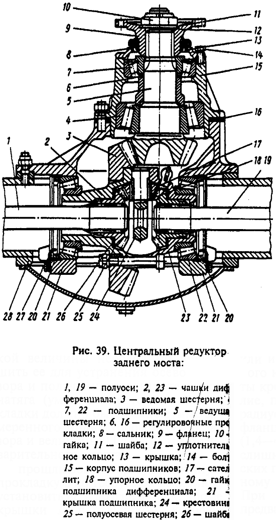
Every 60-80 thousand km of run, it is recommended to check the axial clearance in the bearings of the driving bevel gear 5 (see Fig. 39) with the cardan shaft removed and the nut tightened with the application of a torque of 450-600 N * m (45-60 kgf * m) 10 flange mountings.
The axial clearance is checked using an indicator device, moving the drive gear from one extreme position to another. In the absence of an indicator, the presence of axial clearance in the bearings is checked by swinging the drive gear by the propeller shaft flange. If there is an axial clearance in the bearings and its value exceeds 0.05 mm or movement of the drive gear is felt, adjustment should be made.
Central gearbox adjustment includes adjustments:
- drive gear shaft bearings;
- differential bearings;
- meshing of bevel gears along the contact patch.
To carry out these adjustments, the central gearbox is removed from the bridge and the necessary partial disassembly of the gearbox is performed.
In the MAZ-5335 car and its modifications, after the end of the adjustment of the gear engagement, all the nuts of the studs fastening the bearing housing to the gearbox housing are tightened, the bearing nut stoppers are installed, the driven gear limiter is wrapped so as to obtain a minimum clearance of 0.15-0.2 mm between the cracker and driven gear (the minimum clearance is set when the driven gear is turned one revolution). After that, the stopper is locked with a lock nut.
| Video (click to play). |
When removing the central gearbox from the MA3-5335 car and its modifications (for adjustment or repair), check the clearance between the end plane of the half-axle gear and the support washer, which is set at the factory within 0.5-1.3 mm. The clearance is checked with a feeler gauge through the windows in the differential cups, when the satellites are pushed to the support washers to failure, and the half-axle gear is pressed against the satellites, that is, is in gap-free engagement with them.
Adjustment of the middle axle of the MAZ-64227 car is similar to the previously described adjustment of the central gearbox of the rear axle.
To check the presence of an axial clearance in the bearings of the drive gear 25 (Fig. 41) and, if necessary, to make adjustments, remove the central gearbox, remove the differential lock mechanism 20, the oil seal cover, remove the axle drive shaft 30 with the center differential 29, turning the shaft 30 until the shooting is installed on the differential cups against the gear, remove the crankcase 7. After that, by unscrewing the fastening nuts, remove the crankcase 8 of the bearings with the gear 3.
The design of the drive axles allows you to carry out most of the repair work without removing them from the vehicle.
It is recommended to disassemble the central gearboxes of the middle and rear axles using a universal puller (Fig. 59) and a set of mandrels (Fig. 60) to it.
To replace the drive bevel gear oil seal, you must:
· Disconnect the propeller shaft;
· Unscrew the nut securing the flange 9 (see Fig. 55), remove the washer, seal and flange;
· Unscrew the bolts and remove the cover 13 with the oil seal;
· Replace the oil seal, avoiding its distortions and damage, filling its internal cavities with lithol-24 grease, and reassemble the unit in the reverse order.
The gland is pressed into the cover to a depth of 6 mm from the front end of the cover using a mandrel (Fig. 61). Tighten the nut 10 for fastening the flange with the application of a torque of 45-60 kgf.m.
To remove the gearbox, proceed as follows:
· Drain the oil from the axle housing (after unscrewing the drain and filler plugs);
· Disconnect the propeller shaft;
· Remove the covers 9 (see Fig. 56) of the wheel gears, take out the axle shafts together with the driving gears of the 4 wheel gears;
· Unscrew the nuts of the studs securing the gearbox to the axle housing (except for the two upper ones). After that, roll the cart with a lift under the gearbox and, ensuring reliable support of the gearbox on the cart, unscrew the remaining two upper nuts, then using two dismantling bolts (in the flange of the gearbox to the axle housing) remove the gearbox.
It is recommended to disassemble the gearbox on a special rotary stand. In the absence of a stand, you can use a low table - a workbench with a height of 500 - 600 mm.
The sequence for disassembling the gearbox is as follows:
· Remove the drive gear 5 (see Fig. 55) with the bearing assembly;
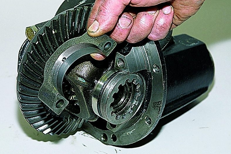
· Remove the stoppers and unscrew the nuts 20 of the differential bearings, loosening the bolts securing the covers 21;
· Remove differential bearing covers 21;
Unscrew the nuts of the bolts of the differential cups and using
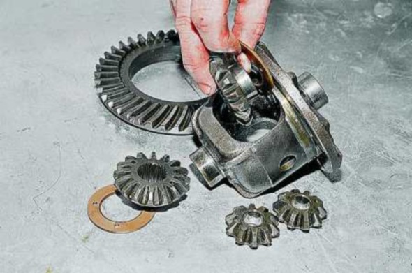
dismantle bolts to disassemble the differential (remove the satellites, side gears, thrust washers);
· Remove, if necessary, differential bearings 22 using a universal puller;
· Clamp the drive gear in a vice, the jaws of which are covered with linings of soft metal, unscrew the nut and remove the drive gear flange 9, cover 13 with an oil seal;
· Remove housing 15 with bearings;
· Remove the inner ring of the inner tapered bearing from the pinion shaft using a universal puller with a mandrel b (see Fig. 60);
If necessary, press out the outer bearing races of the pinion gear from the bearing housing using a puller (Fig. 62) without ring 6.
The nominal and permissible without repair dimensions of the parts of the rear and middle axles are given in table. 9.
In order to make the correct adjustment of the MAZ rear axle, it is necessary to check the presence of an axial clearance of all bearings. Therefore, we advise you to check the clearance after sixty to eighty kilometers of the vehicle's run.
When performing repairs, do not forget to dismantle the MAZ cardan.
Using the indicator device, check the gap as follows: move the gear from the extreme position.
However, if you don't have an indicator, do the following.
Grasp the gimbal flange.
If even a small gap appears (more than 0.05 millimeters), we advise you to adjust the rear axle gearbox for MAZ.
To do this, you need to adjust the position of such units as:
- Differential bearings MAZ;
- Gear shaft bearings;
- The engagement of all gears.
Before that, we recommend dismantling the gearbox from the MAZ bridge, having previously checked the presence of a gap between the washer and the side gear. for this, use a special device - a dipstick.
The distance should be no more than 1.3 and no less than 0.5 millimeters.
The gear bearings must also be checked for clearance. When adjusting the MAZ gearbox, we dismantle it. We also remove the mechanism for locking the MAZ differential, the shaft (in the photo, the part is marked with the number 30), the oil seal cover.
In this case, it is necessary to turn the shaft 30 before installing the shooting on the cups of the unit against the gear.
When adjusting the MAZ rear axle reducer, the crankcase is also removed 7. For this, carefully unscrew the fastening nuts. Then take out the crankcase numbered 8 with gear numbered 3. Read more about replacing the gearbox at MAZ here. You can buy all the necessary spare parts for repair in the MAZ catalog.
The central gearbox of the rear axle, after being removed from the car for repair, is disassembled on a workbench with a height of 500-600 mm in the following sequence:
- remove the drive gear 5 (see Fig. 1) with the bearing assembly;
- remove the stoppers and unscrew the nuts 20 of the differential bearings, loosening the bolts securing the covers 21;
- remove the differential bearing caps 21;
- unscrew the nuts of the bolts securing the differential cups and disassemble the differential using the dismantling bolts (remove the satellites, half-axle gears, thrust washers);
- remove, if necessary, differential bearings 22 using a universal puller;
- clamp the drive gear in a vice, the jaws of which are covered with linings of soft metal, unscrew the nut and remove the drive gear flange 9, cover 13 with an oil seal;
- remove housing 15 with bearings; remove the inner ring of the inner tapered bearing from the pinion shaft using a universal puller with a mandrel (Fig. 2);
- if necessary, press out the outer bearing races of the pinion gear from the bearing housing using a puller (Fig. 3) without ring 6.
The disassembled parts of the central gearbox are washed and carefully inspected. They check the condition of the working surfaces of the bearings: they should not have chipped places, cracks, dents, peeling. The rollers and cages must also be free from destruction and damage. Gear teeth should not have chips and breaks, cracks, chipping of the grout layer, pitting. The nicks and burrs on the gear teeth must be removed and cleaned. The wear of the teeth of bevel gears in thickness is characterized by the value of the lateral clearance with a correctly adjusted engagement (along the contact patch). The gap is measured with an indicator on the large diameter side. With an increased noise of the gears of the central reducer, the value of the lateral clearance of 0.8-0.9 mm can serve as a basis for replacing the bevel gear pair.
If it is necessary to replace one of the gears, it is necessary to completely replace the drive and driven bevel gears, since at the factory they are matched in pairs according to the contact patch, side clearance and are marked with the same number.
When inspecting the parts of the differential, you should pay attention to the condition of the surface of the necks of the cross, holes and spherical surfaces of the satellites, the supporting surfaces of the half-axle gears of the support washers and the end surfaces of the differential cups. These surfaces must not be scored. In case of significant wear or loose fit of the bronze satellite bushing, it must be replaced.
The new sleeve should be processed after pressing it into the satellite to a diameter of 32 + 0.05 mm. With significant wear of the bronze support washers of the side gears, the latter must be replaced. The thickness of the new bronze washers is 1.5 mm. Differential cups, if it is necessary to replace one of them, are completely replaced.
The gearbox housing is made of KCH 37-12 ductile iron. The main defects in which the crankcase is restored is the wear of the holes for the bearing housing and the holes for the rear bearing of the drive gear shaft, damage to the thread under the differential bearing nuts.
Adjustment of the central gearbox of the MAZ vehicle is carried out with the gearbox removed in the following sequence:
1. Adjust the tapered bearings of the pinion pinion.
2. Adjust the differential bearings.
3. Adjust the meshing of the bevel gears according to the contact patch.
You can determine this moment torque wrench on the nut 26 or by measuring the force applied to the hole on the flange for the propeller shaft bolts. The force applied perpendicular to the radius of the holes in the flange should be 1.3-3.9 kg. It should be remembered that too much interference in tapered bearings leads to their strong heating and rapid wear. With normal bearing preload, remove the nut from the drive gear shaft, noting its position, and the flange; refit the cover 24 with the gland and finally assemble the assembly.
Before adjusting the differential bearings and adjusting the meshing of the bevel gears of the main drive, it is necessary to unscrew the deformation limiter 4.
Differential bearing tightening adjustment is carried out using nuts 9 and 15, which must be screwed to the same depth so as not to disturb the position of the gear until the required preload in the bearings is obtained.
Preload bearings is determined by the magnitude of the moment required to turn the differential, which should be in the range of 0.2-0.3 kgm (with the leading bevel gear removed).
This moment is determined by a special torque wrench or by measuring the force applied at the radius of the differential cups and equal to 2.3-3.5 kg.
The procedure for checking and adjusting the meshing of MAZ bevel gears is as follows:
1. Before installing the crankcase of 19 bearings with a driving gear in the gear housing, wipe the teeth of the bevel gears dry and lubricate 3-4 teeth of the driving gear with a thin layer of paint over their entire surface.
2. Install the crankcase 19 with the drive gear in the gearbox housing, screw the nuts on four crosswise pins and turn the drive gear by the flange 25 (in one direction and the other).
3. According to the prints (contact spots) obtained on the teeth of the driven gear, it is determined, guided by the instructions in Table 1, the correctness of the gearing of the gears and the nature of the gearing adjustment.
4. Guided by Table 1, adjust the meshing of the gears by changing the number of gaskets 29 under the flange of the bearing housing of the drive gear and using nuts 9 and 15, without disturbing the adjustment of the differential bearings. In order to move the drive gear away from the driven gear, it is necessary to put additional shims under the crankcase flange, and, if necessary, to bring the gears closer together, remove the gaskets.
For moving driven gear use nuts 9 and 15.
In order not to disturb the adjustment (bearings 33 of the differential, it is necessary to tighten (unscrew) the nuts 9 and 15 at the same angle.
When adjusting the gearing (by the contact patch) on the gear teeth, it is necessary to maintain the required lateral clearance between the teeth, the value of which for a new pair of gears should be within 0.2 to 0.5 mm. Decrease side clearance between the teeth of the gears due to the displacement of the contact patch from the recommended position is not allowed, as this leads to a violation of the correct engagement of the gears and their rapid wear.
After finishing the adjustment gear meshing it is necessary to tighten all the nuts of the studs securing the bearing housing to the gearbox housing, put the stoppers of the bearing nuts, screw the stopper so as to obtain a minimum clearance of 0.15-0.2 mm between the cracker and the driven gear (the minimum clearance is set when the driven gear is turned by one revolution) ... After that, stop 4 must be locked with a lock nut.
When withdrawing central gear from the car MAZ (for adjustment or repair) it is necessary to check the gap between the end plane of the side gear and the support washer, which is set at the factory within 0.5-1.3 mm.
The clearance is checked with a dipstick through the windows in the differential cups, when the satellites are pushed to the support washers to failure, and side gear pressed against the satellites, i.e. is in gap-free engagement with them.
Table 1. Adjusting the meshing of the bevel gears of the central gear
The position of the contact spot on the driven gear
Adjustment of the central gearbox of the rear axle of MA3-5335, MAZ-5549, MAZ-5429, MA3-5430, MAZ-504V
Adjustment of the central gearbox must be done with the gearbox removed in the following sequence:
1. Adjust the tapered bearings of the pinion pinion.
2. Adjust the differential bearings.
3. Adjust the meshing of the bevel gears according to the contact patch.
To adjust the bearings of the drive bevel gear, you must:
1. Disassemble the parking brake, remove the caliper from the crankcase 19 (Fig. 21).
3.Unscrew the nuts of the studs securing the bearing housing of the pinion gear and, using the dismantling bolts 6, remove the housing 19 with the pinion pinion assembly.
4. Fixing the crankcase 19 in a vice, determine the axial play of the bearings with the indicator.
5. Having released the crankcase 19, clamp the drive bevel gear in a vise (put soft metal linings on the vise jaws). Unscrew and unscrew the flange nut 26, remove the washer and flange. Remove the cover with the dismantling bolts. Remove slinger 23, front bearing inner race and shim 21.
6. Measure the thickness of the adjusting washer and calculate to what value it is necessary to reduce it to eliminate the axial play and obtain a preload (the decrease in the thickness of the washer should be equal to the sum of the axial play of the shaft measured by the indicator and the value of 0.03-0.05 mm of the preload).
7. Grind the adjusting washer to the required value, install it and other parts, except for the cover 24 with the oil seal, which should not be installed, since the friction of the oil seal against the flange neck will not allow accurately measuring the torque of the gear turning resistance in the bearings. When tightening the flange nut, the bearing housing must be rotated so that the rollers are correctly positioned in the bearing races.
8. Check the preload of the bearings according to the value of the moment required to turn the drive gear, which should be equal to 0.1—0.3 kgf • m.
This moment can be determined with a torque wrench on the nut 26 or by measuring the force applied to the hole on the flange for the propeller shaft bolts. The force applied perpendicular to the radius of the hole on the flange should be 1.3-3.9 kg. It should be remembered that too much interference in tapered bearings leads to strong heating and rapid wear. With normal bearing preload, remove the nut from the drive gear shaft, noting its position, and the flange; refit the cover 24 with the gland and finally assemble the assembly.
Table 3
Adjusting the meshing of the bevel gears of the central gear
Before adjusting the differential bearings and adjusting the meshing of the bevel gears of the main drive, it is necessary to unscrew the deformation limiter 4.
Adjustment of the differential bearing tightening is carried out using nuts 9 and 15, which must be screwed to the same depth so as not to disturb the position of the gear, until the desired preload in the bearings is obtained.
The preload of the bearings is determined by the value of the moment required to turn the differential, which should be in the range of 0.2-0.3 kgf * m (with the leading bevel gear removed).
This moment is determined by a special torque wrench or by measuring the force applied at the radius of the differential cups and equal to 2.3-3.5 kg.
The procedure for checking and adjusting the meshing of bevel gears is as follows:
1. Before placing the crankcase of 19 bearings with a driving gear in the gear housing, wipe the teeth of the bevel gears dry and lubricate 3-4 teeth of the driving gear with a thin layer of paint over their entire lateral surface.
2. Install the crankcase 19 with the drive gear in the gearbox housing, screw the four crosswise nuts of the studs and turn the drive gear by the flange 25 (in one direction and the other).
3. According to the prints (contact spots) obtained on the teeth of the driven gear, set, guided by the instructions of the table. 3, the correctness of the meshing of the gears and the nature of the adjustment of the meshing.
4. Guided by the table. 3, the meshing of the gears is adjusted by changing the number of gaskets 29 under the flange of the bearing housing of the drive gear and using nuts 9 and 15, without disturbing the adjustment of the differential bearings.In order to move the drive gear away from the driven gear, it is necessary to put additional shims under the crankcase flange, and, if necessary, to bring the gears closer together, remove the gaskets.
To move the driven gear, nuts 9 and 15 are used.
In order not to disturb the adjustment of the differential bearings 33, it is necessary to tighten (unscrew) the nuts 9 and 15 at the same angle.
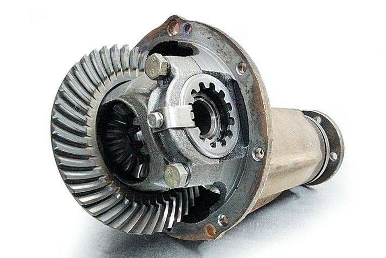
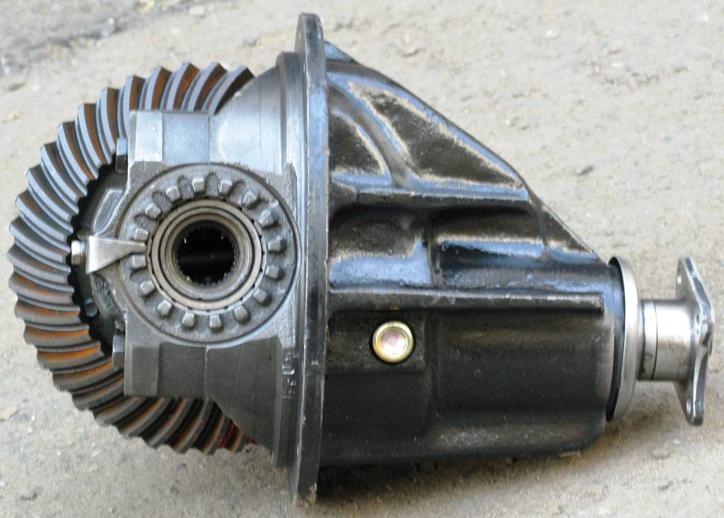
Rear axle reducer is a hypoid mechanical device, where there is a shank (drive gear), and the plane of the driven gear intersects, creating a torque character by means of angular transformation.
To perform such actions, we need: a strong thread, a torque wrench, adjusting rings, fine sandpaper and a vernier caliper.
The gearbox must be adjusted if a hum occurs at a speed of more than 30 km / h. The reason for this failure of the device, as a rule, is the prolonged operation of the car in difficult conditions. Constant overload, driving with a trailer.
Initially required to inspect reducer... It is necessary to brush all the elements, wash them in kerosene. If any defects are visible (damage to the gear teeth), then it is imperative to replace the damaged part. Take a look at the edges at the top of the teeth and the work surface - should be sharp. In the case of the presence of curvatures, nicks, it is worth changing the main pair. Minor defects are eliminated with fine sandpaper, and later polished.
During the assembly of the gearbox, install the spacer sleeve, a new flange nut, and a collar. If the device is assembled in an old crankcase, then calculate the change in the indicators of the drive gear, the adjusting ring. This is how you will determine the difference in thickness deviation between the new and the old model. Such designations are marked with marks "-", "+", the unit of measurement is hundredths of a mm, the data is present on the shaft at the drive gear. We clean the seats under the bearings with a fine sandpaper, a sliding fit should form. Then we press the outer rings of the bearings into the crankcase. Install the inner ring at the rear bearing into the crankcase. Now the flange from the drive gear, the inner ring of the front bearing is secured with a nut, until a moment of 1 kgf.m.
We install the crankcase with a level in a horizontal position. In order to clarify the format of the gap between the plate and the round rod, which is placed in the bearing bed, we will use a flat feeler. The resulting difference will reflect the thickness of the adjusting ring itself. We will use a piece of pipe that is suitable as a mandrel. Install the adjusting ring on the shaft. We mount the shaft itself in the crankcase. We form the parts in the following order: a spacer sleeve and an inner ring from the front bearing, then a collar, a drive gear flange. Using a torque wrench, we tighten the nut to a torque of 12 kgf.m. We tightly wind a strong thread on the neck of the flange, hooking a dynamometer to it. So we find out the scrolling moment formed at the drive gear shaft. The flange should turn with a force of up to 9.5 kgf, if new bearings are installed. If this is not the case, tighten the nut.
The tightening torque should not exceed 26 kgf.m. Otherwise, you have to disassemble the gearbox itself, replacing the spacer sleeve. Install the crankcase with bearings in the differential housing. The bearing cover is secured with bolts. If there is an axial play on the gears of the axle shafts, then use a thicker adjusting ring. The semi-axle gears must fit tightly. Here you can use a steel key (3 mm thick).
Then adjust the tension of the differential bearings, the gap present in the main pair. To check the distance at the covers, use a vernier caliper. We tighten the second nut until it stops.This gap between the covers will be slightly larger, by 0.1 millimeter. During the rotation of the first nut, e the gap is set in engagement. A slight rattling of the teeth will be accompanied by a correct repair. Then both nuts are tightened, the size of the mesh in the engagement is monitored. Tighten the nuts until the distance between the covers is no more than a standard 0.2 millimeters. Then the driven gear is turned three turns, checking the backlash in the engagement of each pair of teeth. We mount the locking plates.
The serviceability of the gearbox should be constantly monitored, since its breakdown can damage the propeller shaft. In addition, the transmission oil must be constantly monitored and changed regularly. In this article I will tell you how the gearbox works, how to properly diagnose it, adjust and repair it.
The rear axle reducer is involved in transferring engine power to the wheels. The main units of the gearbox are: the main gear (GP) and the cross-axle differential. With the help of the gearbox, the rotation speed changes when the force is transmitted from the device to the device. The gearbox design is almost the same for different vehicles.
- leading and driven gears;
- direction pin;
- oil seals;
- drum;
- bearings and their mountings;
- locking plate;
- breather;
- shank and many other details.
The main gear consists of 2 gears: leading and driven. Due to the fact that they are in hypoid engagement, the teeth of the gears have good longitudinal sliding. Thus, the service life is extended and the noise during the operation of the gearbox is reduced. Engine power is transferred first to the drive gear and then to the driven gear. Thanks to this pair, the magnitude of the moment and its direction change.
GP can be single or double. It serves to transfer the engine torque to the wheels. Dual gears are divided into center and split gears. In doubles, the main load falls on the system elements, they have a large gear ratio and have a simple design. Spaced gears make it possible to increase ground clearance, but they are more complex in design, while being more compact and efficient.
A single transmission can be:
- cylindrical. In this case, the gears are in the same plane, have the maximum efficiency;
- hypoid. It has low weight, smaller overall dimensions and average efficiency;
- conical. In this case, the gears are perpendicular to each other, so the structure takes up a lot of space. Has a high efficiency;
- worm. It is compact, works silently, but has the lowest efficiency.
The most common is hypoid transmission. On closer inspection of this gear, you can see that its teeth are located at a slight angle to each other. This reduces the load on the teeth and ensures quiet and smooth operation.
The cross-axle differential works in tandem with the main drive. It includes a driven gear, semi-axle gears and satellite gears. Through the driven gear, the engine power is transmitted to the axle shafts, which transmit it to the wheels. Thus, the differential serves to distribute power between the axle shafts, allowing them to spin at different speeds when changing direction. This principle is applied to rear wheel drive vehicles. This design has proven its reliability and ability to work in the most difficult conditions.
The rear axle gearbox is under the greatest stress, therefore it must be correctly assembled and free from any defects. Only in this case will it last long enough. The service life of the gearbox depends on its maintenance and the adjustment of the rear axle gearbox.
The basis for diagnosing the rear axle gearbox is the noise that appears from the rear of the car. This could be a sign of wear and tear on the device.If a hum appears, then this indicates that the gearbox has become unusable and requires major repairs, in which almost all parts will have to be changed. In order to prevent this condition, it is necessary to make diagnostics in time at the slightest noise.
Typically, different types of noise appear at certain speeds. For each type of noise, you can determine which deviations and with which parts or nodes they are associated. When noise appears in the rear axle, the condition of the drive axle and the gearbox should be checked under different driving modes: moving from a standstill, acceleration, driving at low speeds, etc. Noises during such tests can be divided into the following types:
- continuous noise from the rear wheels;
- noise when accelerating a car;
- noise when braking (slow motion);
- cornering noise.
Having carried out diagnostics by changing the driving modes, you can determine the cause of the malfunctions and roughly make up the amount of repair work.
If the gearbox is out of order, then there are two ways to solve the problem: replace the entire unit or find a faulty part and replace it. To complete the replacement procedure, you will need a standard set of tools. First of all, the oil must be drained from the unit housing. To do this, unscrew the drain plug at the bottom of the rear axle. Next, the rear wheels, brake drums, pads are removed. Using a socket wrench, the axle shafts are unscrewed. Then the axle shafts are dismantled.
There are some special features when dismantling the propeller shaft. Before unscrewing the bolts holding the shaft, it is necessary to note the position of the cardan flange and the gearbox flange relative to each other, so that they can be correctly installed during reassembly to eliminate unbalance. During assembly, the nuts will need to be replaced with new ones so that they do not loosen and the propeller shaft does not break when the car is moving.
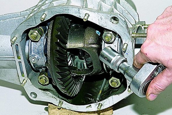
Now, with the help of a socket wrench, the bolts with which the gearbox is attached to the axle are unscrewed. After all these procedures, you can remove the old unit and put a new or repaired one in its place and you can adjust the gearbox. The assembly must be carried out strictly in the reverse order. Fill with new oil.
Adjustment of the rear axle gearbox is performed when a rumble appears in the rear wheels. The hum can be caused by constant stress on the car or mechanical damage. You should start with a visual inspection of the parts. Bearings, oil seals, satellites, flanges and axles are removed from the machine. All parts must be rinsed in kerosene and a visual inspection must be done. If even one tooth is found to be damaged, the part must be replaced with a new one.
After inspection and replacement of parts, the gearbox is assembled. First, the pinion gear is installed with an adjusting washer, spacer sleeve, bearings and flange. A special wrench with a built-in dynamometer is used to tighten the nut. The nut must be tightened by 1 Newton. Further, the driven gear is installed in the differential housing and the bolts are tightened. Now you need to adjust the backlash. When everything is installed, the nuts should be tightened to a minimum. Next, the slave turns, then we check it for a slight backlash. It is needed as a reserve when the gearbox warms up so that nothing bursts during movement.
In the final step, all distances between the bolts holding the nuts are checked. Having checked the distances with a caliper, the nuts are tightened by the same amount on the reverse side of the plane. At the same time, we constantly check the distances between the bolts, they should not change more than 1.5-2 mm. If everything is in order, the gear backlash is checked again, it should be the same as we set it. This completes the adjustment.
The recording shows the classic way of adjusting the gearbox of rear-wheel drive vehicles using specialized devices.
The design of the drive axles allows you to carry out most of the repair work without removing them from the vehicle.
It is recommended to disassemble the central gearboxes of the middle and rear axles using a universal puller (Fig. 59) and a set of mandrels (Fig. 60) to it.
To replace the drive bevel gear oil seal, you must:
· Disconnect the propeller shaft;
· Unscrew the nut securing the flange 9 (see Fig. 55), remove the washer, seal and flange;
· Unscrew the bolts and remove the cover 13 with the oil seal;
· Replace the oil seal, avoiding its distortions and damage, filling its internal cavities with lithol-24 grease, and reassemble the unit in the reverse order.
The gland is pressed into the cover to a depth of 6 mm from the front end of the cover using a mandrel (Fig. 61). Tighten the nut 10 for fastening the flange with the application of a torque of 45-60 kgf.m.
To remove the gearbox, proceed as follows:
· Drain the oil from the axle housing (after unscrewing the drain and filler plugs);
· Disconnect the propeller shaft;
· Remove the covers 9 (see Fig. 56) of the wheel gears, take out the axle shafts together with the driving gears of the 4 wheel gears;
· Unscrew the nuts of the studs securing the gearbox to the axle housing (except for the two upper ones). After that, roll the cart with a lift under the gearbox and, ensuring reliable support of the gearbox on the cart, unscrew the remaining two upper nuts, then using two dismantling bolts (in the flange of the gearbox to the axle housing) remove the gearbox.
It is recommended to disassemble the gearbox on a special rotary stand. In the absence of a stand, you can use a low table - a workbench with a height of 500 - 600 mm.
The sequence for disassembling the gearbox is as follows:
· Remove the drive gear 5 (see Fig. 55) with the bearing assembly;
· Remove the stoppers and unscrew the nuts 20 of the differential bearings, loosening the bolts securing the covers 21;
· Remove differential bearing covers 21;
Unscrew the nuts of the bolts of the differential cups and using
dismantle bolts to disassemble the differential (remove the satellites, side gears, thrust washers);
· Remove, if necessary, differential bearings 22 using a universal puller;
· Clamp the drive gear in a vice, the jaws of which are covered with linings of soft metal, unscrew the nut and remove the drive gear flange 9, cover 13 with an oil seal;
· Remove housing 15 with bearings;
· Remove the inner ring of the inner tapered bearing from the pinion shaft using a universal puller with a mandrel b (see Fig. 60);
If necessary, press out the outer bearing races of the drive gear from the bearing housing using a puller (Fig. 62) without ring 6.
The nominal and permissible without repair dimensions of the parts of the rear and middle axles are given in table. 9.
Strongly bad to say about the rear axle of the five hundredth Mazda I can not say, but breakdowns are not frequent nevertheless present. Once the planetary gear was torn up, it was necessary to look for the side gear. The second trouble happened much later, the driven gear came off the differential.
View of the rear wheel with the MAZ-500 rear axle. The cover of the final drive is clearly visible
After knocking out the old bolts from the hub, I hammered new ones into the hub. The hub was installed in place. He put on a spacer made of the front crown. But when I began to install the crown, I did not like the fastening of the crown to the hub. I remember well that when installing the crown on the Rabo Manov hub, either split crackers or flare nuts were installed on each stud. And on the Mazov hub they are attached only with engraver's washers and nuts. In a word, I decided to additionally strengthen this unit. While I was picking up the cone crackers, I found out that on Kamaz presses the bracket of the upper reaction rod to the bridge just such crackers. In the store it is not a problem to take 24 pieces. I went to the turners with crowns with the hope that milling a cone in the crown would not be a problem for them.So it turned out, they did this work without any problems. All that was left was to assemble. The assembly was not particularly strained and everything fit perfectly. The only thing that alerted me was that all the bolts that fasten the crown were three cm long. In one word, I calmly worked on a little without hesitation about the problem with the bridge, After all, the pocket does not pull the stock.
The table of speeds of the bridge with ID-304 rubber and onboard 3.11 the total gear ratio of the bridge 8.29.
Having traveled for a sufficient time and having no problems with my own bridge, I began to forget about my reserve. But on old cars, the carefree time does not last long. On one of the flights, vibration appeared. After inspecting the car, I saw an extruded bearing of the crosspiece. It was about 150 km to the house and I did not attach any importance to this malfunction. From practice, I drove up to 400 km on such a crosspiece and did not have any negative consequences. Vibration was especially sensitive at 60 km and therefore I drove kilometers. 10 less on the speedometer so that vibration is not heard. The strangest thing is that I did not reach the garage 5 kilometers and the car lost speed. The cardan was spinning, but the car did not move at all. One tie and into the garage. In the garage I was surprised I found out that the central gearbox was weakened and oil leaked out. This is what vibration can lead to. (So that the gearbox loosened up, this was my only case) When the gearbox was removed, the picture became even worse. The bearing seats in the housing are broken and the gears are just in the trash. And there is no one to blame. It was comforting that there was a reserve.
The table of speeds of the MAZ-500 bridge with ID-304 rubber and 2.9 onboard the total gear ratio of the bridge is 7.73.
Bridge with Super MAZ 7,14 (Final drive =3.43 and central gear = 2.0833 25 planetary teeth and 12 shank) and rubber ID-304 vehicle speed. Statistical radius =0.526 m. As can be seen from the tables, due to a decrease in the gear ratio of the Superovsky bridge, the maximum speed increased bya 5 km / h.
In the course of work, I checked the crown tightness three or four times at first, and then calmed down a little I began to check it once a month. After how many years have passed, I can confirm the reliability of the crown fastening by means of engravers' tapered washers and nuts. And for myself I concluded that the plant saved on tapered washers, and in my opinion, this weakened the attachment point. Replacing the bridge with a faster one made it possible to keep more freely in the stream, increased speed and improved braking efficiency. The speed increased especially noticeably on not very hilly terrain. Kinetic speed makes it easier to maintain higher speed. Also worth noting is the sturdier structure of the entire bridge. Large powerful wheel bearings, powerful brakes. And the cases of a weakening shank are completely gone. The only drawback is that I had to tinker a little with it.
Rear view of the installed bridge from Super
| Video (click to play). |
View from the left side of the hub and rubber I-11

