In detail: do-it-yourself ant motor scooter gearbox repair from a real master for the site my.housecope.com.
When buying, the previous owner talked about the recent replacement of the gearbox due to the failure of the old one.
On occasion, photos of the same “covered” gearbox and the new gearbox (before its installation) were published. Broken gear:
Younger gearbox (new):
To remove the gearbox, you need to completely disassemble the entire rear suspension. The oil has been drained. The rear axle is removed. When draining the oil, we did not find it. About twenty (or even less) grams of marsh-colored liquid flowed out of the drain hole. This liquid turned out to be an emulsion (oil with water). Gearbox with axle top view:
In appearance, you can't say about its recent replacement:
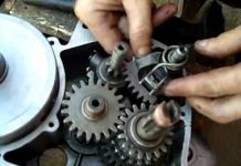
Dismantling the gearbox. As you would expect, everything inside the parts is covered with an emulsion:
After rinsing the parts and inspecting them, a comforting conclusion was made that the gearbox would live (they did not have time to leave it):
All parts are installed in one of the halves of the gearbox housing:
The halves of the crankcase are screwed together, the next step is to install the bearing caps:
Bearing cover with shaft seal:
Top view (right), bottom view (left):
Front view (right), back view (left):
After assembly, the gearbox was tested successfully. Differential and reverse work.
I decided to fence myself a walk-behind tractor for the household. I already had an engine ideally suited for this business - from the SZD motorized carriage. But I did not have a suitable gearbox through which it would be possible to increase the total gear ratio of the transmission and at the same time realize the ability to move in reverse.
| Video (click to play). |
So I thought this way and in the end I decided to "dance" from some mass-produced gearbox or, at worst, adapt a box from "Ural" for this business. I didn't have to look for the device I needed for a long time: on the occasion, two killed "Maravyevsky" gearboxes were presented to me. One of them, twenty years ago, "caught a wedge" and was left in the barn awaiting its finest hour, and the second still showed signs of life, but had serious damage to the body and severe wear of the gear teeth and bearings.
After disassembling both copies, it turned out that the main shaft support bearing crumbled in the jammed gearbox. It would be okay, you might say as usual, but the whole problem was that, during operation, the balls of the crumbled bearing got between the teeth of the gears, which led to their breakage. Everything else, including the body and the internals of the differential, was, to my great joy, unharmed. The internal parts of the second gearbox turned out to be in much better condition, but nevertheless, years of merciless exploitation left their negative imprint on their condition.
I first wanted to buy damaged parts from the store. Oddly enough, the spare parts I needed were found in the store - I don't want to take it. And most importantly, the spare parts were still Soviet-made, coated with a thick layer of grease and wrapped in special paper - not 100% China. But the price for them made me think ... In general, for two gears and an intermediate shaft, the trader asked me for more than two rubles + new bearings, a piece of paronite for a gasket and a set of oil seals, and at all - the price loomed under three rubles ...
I thought, I thought, and decided to limit myself to buying new bearings and oil seals, and borrow the damaged gears and intermediate shaft from another gearbox. In general, to make the gear reducer a classic "brute force", which actually will be discussed in this article.
So, all the parts are cleaned, washed, checked for admissible wear and damage, the thread is driven away, it remains only to collect all this junk "to the heap."
We install the bearings in the gearbox housing preheated with a technical hairdryer. If anyone needs it, I give the bearing numbers:
- 18 GPZ_204_KZ - 2 pcs (primary shaft);
- 4_GPZ_60203_K-2pcs (intermediate shaft);
- 4_GPZ_7_207_K_5-2sht (differential housing);
We put the right half of the body on the planks so that the shafts coming out of the body hang freely in the air and do not interfere with the work. We put a standard thrust washer on the support bearing of the input shaft.
We put the gear on the input shaft as shown in the picture and insert it into the housing. Before installing the gears, pay attention to their teeth and cam couplings, with which the gears mesh with each other. The teeth should be free of chips, damage, cracks and signs of excessive wear. The cams must be of the correct shape with sharp, non-slicked edges.
We put the intermediate shaft in its place.
We thoroughly clean and wipe the working surface of the differential axle shaft and the cup in which the axle shaft enters. We put on a standard thrust washer on the semi-axle and insert it into the cup. We take a set of measuring probes, choose the thinnest one and try to insert it between the working surfaces of the differential cup and its axis. If the selected probe passes between the parts without perceptible effort, take a thicker probe and repeat the procedure again until the probe enters with a noticeable effort.
For me, the measurement process was completed on a probe with a thickness of 0.05 mm, the thicker probe did not pass between the parts, which means that the output in this conjugation does not exceed 0.05 mm. The norm is no more than 0.1 mm. If your measurement procedure ends on a 0, 1 mm or more dipstick, change the half shaft or cup for a new one.
In the same way, we put the satellites on the axis one by one, while carefully making sure that they stand strictly in the place where they stood before disassembly, that is, in the place where the output will be maximum. And we are trying to push a measuring probe between the axis and the inner hole of the satellite. The limit of permissible wear, as in the first case, should not exceed 0.1 mm.
We insert the axis of the satellites into the cup so that it goes slightly over the edge and put a thrust washer on it.
We put the satellite on the axle, push the axle further, put on the second satellite, fit the thrust washer under it and push the axle.
We turn the axis so that the hole for fixing it coincides with the hole in the cup and fix it from falling out with a locking pin.
We connect the cups to each other, put thrust washers on the outer ends of the axle shafts and fix them with retaining rings. The axle shaft can be fixed immediately after installation in the cup, or later - no difference.
We put gears on the differential case. There is no particular difference where to put which gear. It will work either way or not. We put the locking plates on the bolts and tighten the body with them well. Try to tighten the bolts evenly, crosswise and as tightly as possible, several gearboxes passed through my hands in which the bolts were loosened due to which, during operation, both the bolts themselves and the body were broken.
After the final tightening of the bolts, bend the locking plates.
We install the differential housing in its place.
We put on the reverse engagement gear on the fork of the reverse engaging mechanism, put the pin on the fork into the groove on the leash for engaging the reverse, and insert the fork rod into the mounting hole of the body.
Knock out the housing guides so that they come out on the surface of the housing connector by 5-6 mm, degrease the connector planes, apply sealant to the mating surfaces, lay the gasket and connect the halves of the housing.
We tighten the body with bolts, install the axle shaft covers and bearing caps.
The gearbox, which we are going to disassemble today, up to this moment - has been lying around for several years in the barn and was found there by pure chance. Throwing it away is a pity, so it was decided to disassemble it and, if necessary, repair it, for further use as the basis of a homemade walk-behind tractor - no more, no less! Moreover, I have in stock a practically new engine from the SPD, there will be just an excellent pair for this gearbox.
Unfortunately, the technical condition of this gearbox was unknown, during the first inspection some details were revealed: The output shafts of the axle shafts did not rotate, the drive sprocket too ... Most likely the gearbox simply "caught the wedge." Therefore, they took him off and threw him into the barn where he lay for many years ...
We clean the housing from dirt, remove all unnecessary ones, after removing the drive sprocket, it turned out that the input shaft bearing had crumbled.
We unscrew the bolts tightening the gearbox housing, take a construction hair dryer, evenly warm the housing with a hair dryer on all sides, then take a wooden mallet and tap the housing until it splits into two halves.
So the reason for the "wedge" was found - a crumbling input shaft bearing, but these are still "flowers". During the operation of the gearbox, the bearing balls got between the gears, which led to serious damage to the teeth, and this is already serious ... Such gears will have to be replaced with new ones.
The damage to the teeth of the input shaft was the most significant.
Damage to the idler gear teeth.
Crack in the outer bearing race.
We unbend the locking plates and unscrew the bolts tightening the cups of the differential housing, remove the gears.
Disconnect the differential cups.
We remove the locking pin.
Using a special puller, remove the retaining ring and remove the axle shaft from the cup.
The parts of the differential passed the test for "excellent", the teeth of the gears are intact without traces of wear, cracks, workings - as it should be. Permissible wear of rubbing surfaces does not exceed 0.1mm.
Everything is great. Guys, the assembly sequence is exactly the same, or there are some tricks like the checkpoint.
Sergey, there are no tricks and difficulties in assembling the gearbox. But again, before assembly, all the parts must be examined for damage and measurements of the mates must be made - to identify the maximum allowable backlash.
Thank you. Checking the details went well.
Tell me, what is the number of bearings that are on the shaft with splines?
It's no secret that the engineers of the Tula plant have created equipment with which an ordinary owner has to feel like a mechanic. So to this day, having found another problem, the owner of the Ant has to pick up the tool, remembering the would-be engineers. One of the main problems is the motor scooter Ant, which is repaired in most cases of breakdowns.
However, not only the engine can make the motorcycle enthusiast visually see all the components of his motorcycle. The most common problem is dynastarter malfunctions... It, the engineers of the Tula plant, installed it in Ant, instead of the usual alternator.
Why is it so important? If you notice a red light on the dashboard while the moped is running, then you are running out of charging. This is because the generator is not producing alternating current. To begin with, in such a situation, it is necessary to check the integrity of the wires connected to the dynastarter and the relay-regulator. If everything is in order, then the problem lies directly with the dynastarter. It can have three main causes of problems:
- difficulty in the operation of the rotor (dirt or dust accumulation in the collector);
- hanging or wear of the brushes;
- violation of the integrity of electrical equipment.
Since in most cases the work of the dynastarter is difficult due to contamination of the collector, it is worth carrying out a simple disassembly according to the instructions described in the moped's manual.The main rules when working are neatness and cleanliness. After disassembly, be sure to rinse all parts well in gasoline and lubricate rubbing parts and in no case throw parts away.
Unlike the dynastarter, it is difficult to repair the motor scooter Ant with your own hands according to the operation book. Therefore, it is worth referring to the advice of experienced motorcycle owners. Most often, the engine has to be disassembled in case of malfunctions of the clutch mechanisms, the operation of the gearbox, as well as wear of the crankshaft, bearings or oil seals. The most important rule is not to be afraid to disassemble the engine yourself. Using these instructions, disassembly and assembly of the motor scooter Ant will not be difficult.
So, the procedure for disassembling the engine:
-
First, prepare your workplace. If you want to achieve correct and trouble-free operation, keep all parts clean and tidy. Remember and complete the disassembly procedure.
How to assemble the engine of the Ant motor scooter can be seen in more detail in the visual video at the end of the article. The essence of the assembly is in the reverse order, but it is important to tighten the parts with a certain effort and synchronize the parts with the marks. Under no circumstances should you assemble an engine without detailed instructions written by the manufacturer.
With frequent breakdowns, the owners think about what kind of engine can be put on the Ant motor scooter. Instead of a native motor, you can use chinese analog motors... Since the Ant has many copies in Asian countries, replacing the engine can be a great option to save money in the event of irreversible damage. True, you will have to make the fasteners yourself and, in some cases, remake the bridge for the left chain location. This is not very difficult, given that the Tula plant provided for the possibility of rearranging the bridge.
Motor scooter Ant is a cargo motor scooter with a body and its rear axle was created with this in mind (operation on country and rural roads, heavy weight loads). The rear axle "Ant" includes a differential with a main drive, suspension and rear wheel drive.
The final drive increases torque and transfers it to the differential and then to the wheels. The torque is transmitted to the final drive by a chain.
Let's consider how the rear axle nodes work in detail using images:
The differential housing (15) rotates with the driven gear (22). To the body there are bevel gears of the semi-axle (13) and satellite gears (19). Each of the satellites meshes with both gears. When driving on a flat road, the satellites evenly distribute the forces on the bevel gears, rotating on their axis. When the speed of one of the wheels decreases, the satellites begin to rotate, increasing the rotation speed of the other wheel.
- - main gear housing (its left half);
- - the leash of the shift fork;
- - switching fork;
- - axis of the shift fork;
- - main gear housing (right half);
- - the leading gear wheel of the forward motion;
- - chain;
- - an asterisk;
- - stuffing box;
- - drive shaft;
- - bearing 204;
- - metal cardan joint;
- - differential axle;
- - differential housing cover;
- - differential case;
- - chain tensioner;
- - driven reverse gear;
- - the axis of the satellites;
- - satellite gear;
- - stuffing box;
- - bearing 207;
- - driven gear wheel of forward motion;
- - pad;
- - reverse drive gear;
- - intermediate shaft;
- - bearing 203;
- - lid;
- - pin;
- - lid;
Differentials are combined in one unit together with a gear change mechanism for reverse and forward gears.
The main gear is a gear and an intermediate gear (27). The crankcase consists of 2 halves (1) and (5), which were cast from an AL-2 aluminum alloy.The driven sprocket of the drive (8) is installed on the splines of the end of the drive shaft (10) protruding from the housing, which rotates in the crankcase in bearings (11). A drive gear (6) with cams on the left end is freely placed on the shaft inside the crankcase. On the splines there is a primary gear - a clutch (24). The intermediate shaft with gear (27) rotates on 2 bearings (26).
The differential housing (15) with the housing cover (14) are supported by ball bearings (21) pressed into the crankcase. Cover (14) and differential housing (15) are bolted together. The differential contains the driven gears of the forward (22) and reverse (17) travel. Inside the differential housing there are 2 more gears (13) and 2 satellites (19).
The satellites rotate on an axle (18), which is pinned in the body (15). At the ends of the gears (13), there are hinges (12) made of rubber and metal, which are protected by the chelas. The torque is transmitted to the shaft (10) by the chain (7) and the driven sprocket (8).
When the scooter is moving forward, the cams of the gear (24) are in conjunction with the cams of the pinion gear (6), which in turn transmits the moment to the driven gear (22) through the intermediate pinion shaft (27). When reverse gear is engaged, gear (24) meshes with reverse driven gear (17).
In Figure 3: the drive axle shaft (16) transfers rotation from the differential gear to the driven axle shaft. At the ends of the driving axle shaft (16) there are hinged joints - cardan joints. A cardan drive is needed due to the fact that when the rear suspension springs work, the wheels and axle shafts approach and move away from the body.
Metal and rubber hinges are usually fairly durable and require no maintenance. However, care must be taken to ensure that the clutch covers (17) are bolted together. The maximum allowable gap between the shrouds is 0.5 mm. The cuts in the rubber couplings (14) at the locations of the driver forks and the cuts at the places where the covers fit do not affect the operation of the hinges.
When the drive shaft rotates (even at a constant frequency), the angular velocity of the driven shaft changes 2 times per revolution (decreasing and increasing). This uneven rotation is compensated for by cardan joints at both ends of the drive axle shaft (otherwise, significant forces would be created on the driven shaft and wheel bolts, which would lead to increased tire wear).
The rear wheels themselves are driven in the following way: the torque from the differential is transmitted to the driving pluos (19) through the cardan joint and the splined connection. The half-shafts (leading and driven) are connected to each other by another rubber-metal universal joint (26). The wheel hub is seated on a key (8) on the tapered end of the driven axle shaft. The driven axle shaft (1) itself rotates in 2 tapered roller bearings (2), which are pressed into the steel bush of the balancer.
To adjust both bearings, the inner race of the outer bearing is moved on the driven axle shaft. Adjustments can be made with the nuts (5) through the pressure ring. This operation should be carried out carefully, since with a very tight tightening, the bearings get very hot until the grease melts and flows out and the bearing is destroyed. In addition, such a tight tightening can cause the appearance of "cavities" on the tracks of the rings during operation.
So, in order to adjust the bearings, you need to remove the wheel hub. Further, turning the driven semiaxis, tighten the adjusting nut until the semiaxis rotates tightly, after which you need to unscrew the nut by 1-1.25 edges (if the bearings are already running in) or 1.25-1.5 edges (if the bearings are new). After adjustment, the nut should be locked (secured against unscrewing). When attaching the brake drum in place, make sure that the segment key (8) is installed correctly - after assembly, the wheel should rotate freely and at the same time not have a noticeable gap.
After assembly, on the first trips, it is necessary to check the heating of the hubs. Slight heating is not dangerous. Heat, at which the hand "does not tolerate", should be eliminated by unscrewing the nut half more edge. After a run of 200-300 km, you can turn the nut back to its previous state (on the floor of the garni).
When adjusting, do not tighten the nut too weakly, since a strong tightening is easy to notice (by heating the hubs) and tighten, but a weak tightening is difficult to determine and at the same time can lead to a quick failure of the bearings.
Conical bearings are lubricated by filling the inner cavity of the balancer bushing with grease (Litol). Rubber seals (19) fitted on both sides of the bushing prevent grease from escaping.
The rear suspension of the cargo scooter "Ant" transfers the vertical load from the frame to the wheels, and from the wheels to the frame, the braking and pushing forces. The rear wheels have independent suspension (each wheel is connected to the frame by means of articulated arms that allow moving up and down independently of the other wheel). This suspension significantly reduces frame vibrations, especially when driving on uneven, bumpy roads.
The suspension includes balancers and coil springs. Balancer (27) - a welded structure made of pipes in the form of a trapezoid. One end of the structure is welded to a steel bushing. On the frame, the balancer is pivotally reinforced with bushings welded to the other end of the structure and pipes. A rear suspension spring (23) is installed on a bushing welded to the balancer body. The upper spring is mounted on the frame bracket. To prevent contact of the coils and limit compression, there is a rubber buffer (24) inside the spring. Vibrations are damped by spring-hydraulic shock absorbers (25) installed on the balancers.
Rice. 3. Suspension and rear wheel drive: 1 - driven semi-axle; 2 - roller bearing 7205; 3 - persistent ring; 4 - brake cam; 5 — adjusting nut; 6 - lock washer; 7 - retaining ring; 8 - key; 9 - nut; 10 - a cup; 11 - a spring of brake pads; 12 - brake shoe; 13 - bolt; 14 - rubber coupling; 15 - conical washer; 16 - leading semiaxis; 17 - clutch casing; 18 - rear wheel hub; 19 - stuffing box; 20 - small braking rod; 21 - axis; 22 - oiler; 23 - rear suspension spring; 24 - rubber buffer; 25 - spring-hydraulic shock absorber; 26 - cardan joint; 27 - balancer; 28 - bolt-axis; 29 - brake pipe; 30 - brake cam lever; 31 - cotter pin.
Motor scooter Ant is a Soviet motor scooter with three wheels. For the first time, the production of such equipment, which was quite difficult to buy, since it was in short supply at first, was taken up by the Tula Industrial Plant. Later, several modifications of the scooter were released, but all of them were created on the basis of the original version. Now the motor scooter Ant has become a common technique that is available to almost everyone.
Previously, a scooter had one purpose, one main purpose: the transportation of a variety of goods. Of course, at present, the Ant motor scooter is not in such overwhelming demand as during the USSR, so it is very difficult to find spare parts for it now. Nevertheless, in some Asian countries, such a device is still in incredible demand, so it will not be difficult to buy the missing parts here.
The ant is much lighter than conventional motorcycles, so everyone dreamed of buying it. The approximate weight was only 240 kg, which is not enough, considering that he could carry loads several times heavier than himself. Actually, it is because of this that he received the name Ant.
Another advantage of the scooter was and is that you can buy it for a small amount of money. So, you can buy a motor scooter Ant for only 30,000-50,000 rubles.
Ant has a single-cylinder engine.At the same time, it is quite gluttonous, so the language does not turn out to be called an economical technique. After all, even a new engine Ant spends about 8 liters of 80-liter gasoline on a hundred, and what can we say about used equipment? After all, if the piston or gearbox has worn out a little, then the costs increase to 10 liters per hundred. In this case, you can replace damaged parts, but buying them is not easy, since they are rarely found on sale.
Motor scooter engine Ant
You can buy an already assembled Ant engine, but this luxury is a little expensive.
In general, the motor scooter Ant is a very durable technique. The front link suspension is particularly well-designed. She can serve for more than a dozen years. Many scooter users even claim that it is better made than modern telescopic forks.
Now, most of the fans of the Ant motor scooter, instead of the front shock absorbers, install the rear shock absorbers from the scooter, because the former are currently in short supply.
The rear suspension is independent. The gearbox drives the rear wheel. This is facilitated by the roller chain passing through it. At the same time, the gearbox itself is made quite well. Located in the very center of the rear axle, so it can be easily removed if needed.
Due to its low weight, the owner of this technique can easily turn over the Ant motor scooter, which will make it easy to carry out repair work. You don't have to remove the wheel to change the tube, tire, or even the gearbox.
The scooter is large in size, making the equipment perfect for work in the countryside.
The scooter can reach a maximum speed of 50-60 km / h.
Before starting the repair, you need to buy all the necessary parts and tools. Of course, first you need to diagnose the device in order to understand what the problem really is.
You also need to take into account a few tips on how to change certain parts:
- If you want to change a tube or a tire, you don't need to skid the wheel at all. It is enough just to unscrew all the bolts securing it.
- The wheel starts to spin thanks to the roller chain running through the gearbox. In this case, the rear suspension is completely independent.
- The gearbox can be easily removed without any additional tools, because it is located in the very center of the scooter.
The repair is accompanied by the following basic steps:
- drain the oil from the engine, then remove the engine and place it on a flat surface;
- remove the cooling shrouds and dinastrater;
- remove the final drive sprocket;
- release the clutch cover from the bolts and remove it;
- remove several clutch discs;
- after that it will be possible to easily remove the basket together with the chain and sprocket, washer and bushing;
- in order to disconnect the cylinder head, it is necessary to unscrew the four washers that secure it; if there are noticeable seizures on the cylinder mirror, then it should be sharpened;
- remove the cylinder, remove the piston pin ring using round-nose pliers;
- unscrew the crankcase tightening bolts, while an impact screwdriver can help, which is very useful in such cases;
- turn the engine to the disassembled side, gently hit it with a mallet until the crankcase splits into two equal halves;
- put the engine straight, using a mallet, carefully knock out the propeller shaft;
- after that, access to bearings and seals appears.
Usually, the engine stops working if these parts become heavily contaminated. New parts may be needed here - an oil seal or a bearing. Replacing them is quite simple. Sometimes spare parts are not needed: you just need to clean the mechanism from dirt.
But at this stage, many people who have a motor scooter Ant, but who are not familiar with how to properly repair it, make the same mistake. It consists in the following: they close the oil channel with a gasket or lubricate it with a sealant. But this is wrong, since this closes the paths along which the grease passes to the oil seal and bearings. This leads to breakage of parts, so later on, new parts may be needed. They are quite rare on sale. But you can buy spare parts in some online stores, but no one knows what their quality will be.
Reducer Ant is disassembled according to a certain scheme. This process is necessary if, for some reason, the Ant reducer has ceased to function. Some people do it wrong: when a gearbox breaks down, they just throw it away. But after all, with the right approach to this matter, the device can be repaired, after which the Ant motor scooter will function in the same way as before. In addition, it is difficult to buy spare parts for the Ant motor scooter, so you shouldn't waste them in vain.
Motor scooter reducer Ant
- If the gearbox of Ant has been disassembled for some time, then for a start it would be nice to clean it of dust and dirt.
- Remove all bolts that tighten the gearbox. Take a building hair dryer. Use it to warm up the Ant reducer from all sides, then knock on the body with a wooden mallet. Until it splits into two halves.
- Now you can find out what caused the breakdown. The gearbox could fail for two main reasons: the input shaft bearing was broken, or the gear teeth were worn out. Both parts will have to be replaced.
- Gears and bearings must be removed so that they can be exchanged for new parts.
- Remove the retaining plate.
- Remove the retaining ring and remove the axle shaft from the cup.
- Before you start assembling all the parts back, you need to check their integrity. When the Ant reducer is assembled, it can be sent to the designated place for it.
Motor scooter Ant can become a useful type of technology today. If you have your own farm or do gardening in the country, you will not find anything better than such a scooter.
Motor scooter Ant is a cargo motor scooter with a body and its rear axle was created with this in mind (operation on country and rural roads, heavy weight loads). The rear axle "Ant" includes a differential with a main drive, suspension and rear wheel drive.
The final drive increases torque and transfers it to the differential and then to the wheels. The torque is transmitted to the final drive by a chain.
Let's consider how the rear axle nodes work in detail using images:
The differential housing (15) rotates with the driven gear (22). To the body there are bevel gears of the semi-axle (13) and satellite gears (19). Each of the satellites meshes with both gears. When driving on a flat road, the satellites evenly distribute the forces on the bevel gears, rotating on their axis. When the speed of one of the wheels decreases, the satellites begin to rotate, increasing the rotation speed of the other wheel.
- - main gear housing (its left half);
- - the leash of the shift fork;
- - switching fork;
- - axis of the shift fork;
- - main gear housing (right half);
- - the leading gear wheel of the forward motion;
- - chain;
- - an asterisk;
- - stuffing box;
- - drive shaft;
- - bearing 204;
- - metal cardan joint;
- - differential axle;
- - differential housing cover;
- - differential case;
- - chain tensioner;
- - driven reverse gear;
- - the axis of the satellites;
- - satellite gear;
- - stuffing box;
- - bearing 207;
- - driven gear wheel of forward motion;
- - pad;
- - reverse drive gear;
- - intermediate shaft;
- - bearing 203;
- - lid;
- - pin;
- - lid;
Differentials are combined in one unit together with a gear change mechanism for reverse and forward gears.
The main gear is a gear and an intermediate gear (27). The crankcase consists of 2 halves (1) and (5), which were cast from an AL-2 aluminum alloy. The driven sprocket of the drive (8) is installed on the splines of the end of the drive shaft (10) protruding from the housing, which rotates in the crankcase in bearings (11). A drive gear (6) with cams on the left end is freely placed on the shaft inside the crankcase. On the splines there is a primary gear - a clutch (24). The intermediate shaft with gear (27) rotates on 2 bearings (26).
The differential housing (15) with the housing cover (14) are supported by ball bearings (21) pressed into the crankcase. Cover (14) and differential housing (15) are bolted together. The differential contains the driven gears of the forward (22) and reverse (17) travel. Inside the differential housing there are 2 more gears (13) and 2 satellites (19).
The satellites rotate on an axle (18), which is pinned in the body (15). At the ends of the gears (13), there are hinges (12) made of rubber and metal, which are protected by the chelas. The torque is transmitted to the shaft (10) by the chain (7) and the driven sprocket (8).
When the scooter is moving forward, the cams of the gear (24) are in conjunction with the cams of the pinion gear (6), which in turn transmits the moment to the driven gear (22) through the intermediate pinion shaft (27). When reverse gear is engaged, gear (24) meshes with reverse driven gear (17).
In Figure 3: the drive axle shaft (16) transfers rotation from the differential gear to the driven axle shaft. At the ends of the driving axle shaft (16) there are hinged joints - cardan joints. A cardan drive is needed due to the fact that when the rear suspension springs work, the wheels and axle shafts approach and move away from the body.
Metal and rubber hinges are usually fairly durable and require no maintenance. However, care must be taken to ensure that the clutch covers (17) are bolted together. The maximum allowable gap between the shrouds is 0.5 mm. The cuts in the rubber couplings (14) at the locations of the forks of the leashes and the cuts at the places where the covers fit do not affect the operation of the hinges.
When the drive shaft rotates (even at a constant frequency), the angular velocity of the driven shaft changes 2 times per revolution (decreasing and increasing). This uneven rotation is compensated for by cardan joints at both ends of the drive axle shaft (otherwise, significant forces would be created on the driven shaft and wheel bolts, which would lead to increased tire wear).
The rear wheels themselves are driven in the following way: the torque from the differential is transmitted to the driving pluos (19) through the cardan joint and the splined connection. The half-shafts (leading and driven) are connected to each other by another rubber-metal universal joint (26). The wheel hub is seated on a key (8) on the tapered end of the driven axle shaft. The driven axle shaft itself (1) rotates in 2 tapered roller bearings (2), which are pressed into the steel bush of the balancer.
To adjust both bearings, the inner race of the outer bearing is moved on the driven axle shaft. Adjustments can be made with the nuts (5) through the pressure ring. This operation should be carried out carefully, since with a very tight tightening, the bearings become very hot until the lubricant melts and flows out and the bearing is destroyed. In addition, such a tight tightening can cause the appearance of "cavities" on the tracks of the rings during operation.
So, in order to adjust the bearings, you need to remove the wheel hub. Further, turning the driven semiaxis, tighten the adjusting nut until the semiaxis rotates tightly, after which you need to unscrew the nut by 1-1.25 edges (if the bearings are already running in) or 1.25-1.5 edges (if the bearings are new).After adjustment, the nut should be locked (secured against unscrewing). When attaching the brake drum in place, make sure that the segment key (8) is installed correctly - after assembly, the wheel should rotate freely and not have a noticeable gap.
After assembly, during the first trips, it is necessary to check the heating of the hubs. Slight heating is not dangerous. Heat, at which the hand "does not tolerate", should be eliminated by unscrewing the nut half more edge. After a run of 200-300 km, you can turn the nut back to its previous state (on the floor of the garni).
When adjusting, do not tighten the nut too weakly, since a strong tightening is easy to notice (by heating the hubs) and tighten, but a weak tightening is difficult to determine and at the same time can lead to a quick failure of the bearings.
Conical bearings are lubricated by filling the inner cavity of the balancer bushing with grease (Litol). Rubber seals (19) fitted on both sides of the bushing prevent grease from escaping.
The rear suspension of the cargo scooter "Ant" transfers the vertical load from the frame to the wheels, and from the wheels to the frame, the braking and pushing forces. The rear wheels have independent suspension (each wheel is connected to the frame by means of articulated arms that allow moving up and down independently of the other wheel). This suspension significantly reduces frame vibrations, especially when driving on uneven, bumpy roads.
The suspension includes balancers and coil springs. Balancer (27) - a welded structure made of pipes in the form of a trapezoid. One end of the structure is welded to a steel bushing. On the frame, the balancer is pivotally reinforced with bushings welded to the other end of the structure and pipes. A rear suspension spring (23) is installed on a bushing welded to the balancer body. The upper spring is mounted on the frame bracket. To prevent contact of the coils and limit compression, there is a rubber buffer (24) inside the spring. Vibrations are damped by spring-hydraulic shock absorbers (25) installed on the balancers.
| Video (click to play). |
Rice. 3. Suspension and rear wheel drive: 1 - driven semi-axle; 2 - roller bearing 7205; 3 - persistent ring; 4 - brake cam; 5 — adjusting nut; 6 - lock washer; 7 - retaining ring; 8 - key; 9 - nut; 10 - a cup; 11 - a spring of brake pads; 12 - brake shoe; 13 - bolt; 14 - rubber coupling; 15 - conical washer; 16 - leading semiaxis; 17 - clutch casing; 18 - rear wheel hub; 19 - stuffing box; 20 - small brake rod; 21 - axis; 22 - oiler; 23 - rear suspension spring; 24 - rubber buffer; 25 - spring-hydraulic shock absorber; 26 - cardan joint; 27 - balancer; 28 - bolt-axis; 29 - brake pipe; 30 - brake cam lever; 31 - cotter pin.


