In detail: do-it-yourself repair of the rear axle gearbox Moskvich 412 from a real master for the site my.housecope.com.
1. Possible malfunctions of the rear axle of Moskvich 412
2. Scheme of the gearbox of the rear axle AZLK (IZH) 412
3. Sequence of disassembly of the rear axle reducer
4. Links to our forum - ask questions
1. Possible malfunctions of the rear axle of Moskvich 412
- Constant increased bridge noise when driving
one). Incorrect adjustment of the final drive gears - Adjust the position of the gears.
2). Damaged or worn final drive gears - Replace final drive gears. Flush axle housing and fill with oil.
3). Worn or damaged pinion bearings - Replace bearings.
4). Worn or damaged differential bearings - Replace bearings.
- Increased noise when accelerating a car
one). Worn or damaged pinion bearings - Replace bearings if they are not in satisfactory condition.
- Increased noise when coasting
one). Worn pinion bearings - Replace bearings.
- Increased noise when braking the car with the engine
one). Worn or damaged pinion bearings - Replace bearings.
- Increased noise when driving around bends
1). Tight rotation of the satellites - Inspect the working surfaces at the seat of the satellites on the axle. Smooth out minor seizures of surfaces with a fine abrasive cloth. Replace badly worn or damaged parts.
- Knock from the rear wheels when cornering
one). Loosen the bolts securing the axle shaft bearing and the brake shield to the rear axle housing flange - Tighten the bolts.
| Video (click to play). |
2). Axial displacement of the axle shaft in the bearing due to displacement of the locking sleeve or crimping of the thrust sleeve - Press in the locking sleeve (it is better to press in a new one). Replace thrust bush if necessary.
2. Scheme of the rear axle gearbox on a Moskvich car (AZLK and IZH) 412:
Index of gearbox parts for AZLK 412
3. The sequence of disassembling the gearbox on the Moskvich 412 car:
1. Unscrew the bolts (7) and remove the stoppers (10) of the differential bearing adjusting nuts. Mark the differential case bearing caps (8) if unmarked.
2. Remove the bolts (7) securing the differential bearing caps and remove the caps.
3. Remove adjusting nuts (11) and differential with driven gear (2) and bearings.
4. Unscrew the nut that secures the flange to the drive gear shank.
5. Remove the propeller shaft mounting flange.
6. Use a rubber or wooden hammer to knock out the drive gear (1) with the inner ring of the rear bearing, with a spacer sleeve and shims, while supporting the gear by its head with your hand.
7. Install the gearbox housing on a special support with the neck down and, using a mandrel, press out the outer ring of the front bearing at the same time as the slinger washer and the drive pinion oil seal.
8. Press out the outer ring of the rear bearing using a special mandrel inserted into the gearbox through the outer ring. Take out the shims.
9. Remove the shims and spacer from the drive gear.
10. Remove the inner ring of the rear bearing on a hand press, consisting of two half-cylinders connected by a ring.
4. Links to our forum - ask questions
sandblasted the rear axle, resory and painted everything.
put new bearings, oil seals and adjusted the gearbox,
let's see when the Muscovite will ride as he will sing.
Configured as it is written in the book.
All bolts, nuts, washers and other small things anew
galvanized
Moskvich 412 1973, petrol engine 1.5 l., 75 hp sec., rear-wheel drive, manual transmission - DIY repair
3 mm, but 2 mm will do too, relatives were also from the deuce
Are the ears on the spring brackets damaged during parsing? I broke a few. I think now to make new staples.
I put new staples on, my relatives rotted to nothing ...
Found on sale or made?
You can buy from us through EBay, roofing felts from Ukraine, roofing felts from Russia are brought ...
I do not know exactly
Last summer I changed the springs to new ones (mine were too sagging), but since the previous owner wanted to carry more loads on them, he added one additional sheet. The Muscovite was so bullied with them, well, just awful ...
I had to disassemble them and leave 6 sheets as in the original, so I made the staples on them myself, the new-made staples were too thin to look.
And how the bearings were removed from the axle shafts?
I am offered to cut the bushings ...
I made myself an adaptation and pressed it out together with the bearing, in this way the retaining ring remains intact and it can be used again, unless of course there is no working out on it in the gland area
Greatly confused. Nobody will do that to me.
I gave it to the service today, they said it was necessary to cut it.
But I came home and I was wondering if I would find these new bushings later.
And how the bearings were removed from the axle shafts?
I am offered to cut the bushings ...
When assembling the rear axle gearbox, use a hand press, a stand for assembling the gearbox, a rack with a hour indicator, micrometers 0-25 and 25-50, mandrels (9480-1097, 9480-1096, 9480-1099) for pressing in the outer rings of the front and rear bearings (Fig. 119) and the inner ring of the rear bearing (Fig. 120), a mandrel (9480-1098) for pressing in the drive gear oil seal (Fig. 121), a special mandrel (9480-1631) and a micrometer stand (9549-523) for checking installation dimension in the gearbox housing (Fig. 122), telescopic control spacer sleeve (Fig. 123), torque wrench up to 180 Nm (18 kgf checking the frictional moment (shift) of the bearings of the drive gear of the reducer (Fig. 124), a mandrel for pressing in the differential bearings (Fig. 125).
Rice. 119. Rims for pressing in the outer bearing rings of the main gear drive gear: a - for the front bearing ring; b - for the rear bearing ring. Material - steel 45. Heat treatment: heat up to HRC 40-45, release to HRC 28-32
Rice. 120. Mandrel for pressing the inner ring of the rear bearing onto the shaft of the driving gear of the main drive: 1 - mandrel; 2 - bearing ring; 3 - driving gear. Material - steel 45. Heat treatment: heat to HRC 40-45, in section A release to HR C 28-32
Rice. 121. Mandrel for pressing the drive pinion oil seal into the throat of the gearbox housing. Material - steel 45. Heat treatment: heat up to HRC 40-45, in section A release to HRC 28-32
Rice. 122. Special mandrel and micrometric stand for measuring the mounting size in the gearbox housing: a - mandrel; b - micrometric stand. Material - HG steel. Heat treatment: heat-treated, release HRC 58-62. Permissible runout - 0.01 mm
Rice. 123. Telescopic control spacer sleeve for measuring the distance between the inner rings of the drive pinion bearings: Non-parallelism of ends A and B - 0.01 mm. Material - U8 steel. Heat treatment: hot-melt, release HRC 48-52
Rice. 124. Control device for checking the friction (shift) moment of the bearings of the drive gear of the reducer
Rice. 125. Mandrel for pressing in differential bearings: Material - U7 or 40X steel. Heat treatment: hot, release up to HRC 44-48
The durability and quiet operation of the rear axle depends on the correct and accurate assembly of the gearbox.
When assembling the gearbox, the following must be provided:
- Correct mutual installation of the drive and driven gears and the installation of the drive gear according to the mounting dimension "C" (see Fig. 105);
- the required side clearance between the teeth of the driving and driven gears;
- preloading of the drive pinion bearings.
The device and operation of the car Moskvich-412
Our additional services and sites:
Rear axle of the car Moskvich-412
The rear axle, crankcase 18 (Fig. 34) of the axle is welded from two stamped steel halves with a wall thickness of 3.4 mm. Steel flanges are welded to the ends of the crankcase for mounting the axle shaft bearings and fastening the brake shields with brakes, as well as platforms 21 for attaching the springs and the bracket 10 for fastening the pipelines of the hydraulic brake drive.
The extended middle part of the crankcase on the front side has an opening in which the main gear (axle reducer) is located; The cast iron gearbox housing 40 is bolted 36 to the main casing. The rear opening of the axle housing is closed by a convex stamped cover welded to the crankcase with an oil filling hole and a plug 12. The drain hole is located in the lower part of the crankcase.
The main gear with a differential is assembled separately and assembled on the rear axle, after which the axle shafts 35 and the brakes are put in place. The drive gear 7, which has nine teeth, is made in one piece with the drive shaft of the main gear and is installed on two tapered roller bearings 3 and b, between which there is a spacer sleeve 5 and adjusting shims 4, which determine the degree of tightening of these bearings.
Rice. 34. Rear axle: 1 - flange; 2 - nut; 3 and 6 - bearings of the leading Ball; 4 - shims; 10 - differential bearing cover; 11 - differential box; 12 - gear oil plug; 16 - stopper bolt; 17 - adjusting nut stopper; 18 - rear axle housing; 21 - spring cushion (platform); 22 - locking (locking) 25 - bearing mounting plate; 26 - brake shield; 27 -feet oil seal; 28 - air release; 32 - bolt of fastening of the brake mechanism and semi-axle bearing; 33 - adjusting nut; 38 - differential bearing; 39) - half-axle gear;
5 - spacer sleeve; 7 - driving gear; 8 - pin of pin of satellites: 9 - satellite: filling hole; 13 - pin of satellites; 14 - driven gear; 15 - fastening bolt 19 - bracket for pipelines of the hydraulic drive of brakes: 20 - pipe for hydraulic brakes of the semi-axle bearing; 23 - semi-axle rubber oil seal; 24 - cap oil can; thrust sleeve; 29 - brake drum; 30 - wheel brake cylinder; semi-axle bearing: 34 - crankcase flange; 35 - semiaxis; 36 - gearbox housing bolt; 40- gearbox housing; 41 - shims; 42 - stuffing box; a - drainage hole
The inner bearing rings, spacer sleeve with shims and flange 1 for connection to the cardan gear are rigidly fastened with a nut 2 on the drive shaft of the main gear. Nut 2, after tightening with a force of 12.5-14 kgf-m, is fixed by indenting its upper cylindrical belt into the longitudinal groove of the gear shank. The outer rings of the bearings are pressed into the seats of the crankcase all the way into special protrusions, and between the ring of the inner bearing and the protrusion of the crankcase, spacers 41 are placed, which are necessary to adjust the meshing of the gears of the gearbox. The front part of the main drive pinion shaft is sealed in the crankcase with a rubber gland 42. The driven gear has 38 teeth, is centered on a cylindrical groove and is attached to the differential box 11 with eight bolts.
The differential box is installed in the crankcase on two angular contact ball bearings 38, reinforced with removable covers 10. The bearings are fixed and adjusted with shaped nuts 37 screwed into the sockets and fixed stoppers 17. The differential bearing nut stoppers have one on one side, and on the other - two protrusions; by setting the stopper with the right side to the nut, they provide regulation of its tightening with an accuracy of 1/24 turn.
Stoppers are bolted 16 to bearing caps 10. Each of the covers is attached with two bolts to the final drive housing. Boring in the bearing housing covers and threading for the nuts 37 are carried out simultaneously in the crankcase and the bearing caps screwed to it, which is why these covers are not interchangeable.
Inside the differential box, on the pin 13, fixed in the box by the pin 8, two satellites 9 are freely installed, which are bevel spur gears. The satellites are permanently engaged with two half-axle gears 39, which are centered with their ground journals in the seats of the differential box. The half-axle gears in the sockets and the satellites on the finger can rotate freely, remaining interlocked.
The main gears are of the hypoid type with spiral teeth. In the meshing of the hypoid gears, there is a significant mutual sliding of the surfaces of the interlocking teeth, accompanied by their increased heating, therefore, for a hypoid transmission, it is necessary to use only a special hypoid lubricant with a high film strength. The gear ratio of the main transfer is 4.22. The gears at the factory are matched to each other and marked with one number.
By selecting the total thickness of the spacers 41, the required distance C (mounting dimension 53.4 mm) is provided, which determines the correct relative position of the meshed gears.
When a pair of gears of a reducer is selected at the factory, the serial number of the pair and the value of the correction for the mounting dimension with the sign or by which the actual height of the head of this drive gear differs from the nominal height of the head is burned out at the ends. From the differential to the wheels, the torque is transmitted by two identical semi-axles 35.
At the outer ends of the semi-axles, flanges are planted for fastening the brake drums and wheels, and on the inner ends, slots are cut, which, when the semi-axle is installed, enter the slotted hole of the semi-axle gear.
The inner rings of the bearings 33 are fixedly fixed on the axle shafts by locking bushings 22, which are tightly fitted on the axle shaft journal in the hot state. On the other side, the rings abut against thrust bushings 28.
The outer rings of the semi-axle bearings are located in the seats of the axle flanges and are fixedly fixed by plates 25, which are attached to the crankcase with bolts 32 when installing brake shields 26 with a wheel brake pre-mounted on the shield. mechanism. The bearing seats of the axle shafts are sealed with rubber and felt seals 23 and 27. Grease is supplied to the bearings with a cap oiler 24 screwed into the channel of the crankcase flange.
A conical belt is made near the flange of the axle shaft to drain oil from the brake drum to the inner surface of the oil deflector, from where it can drain out through the drain holes in the plate and the brake shield. On the flanges of the axle shafts protruding beyond the rear axle housing, the brake drums 29 and the rear wheel discs of the vehicle are fastened with nuts.
With prolonged movement, the gearbox housing heats up to 70-80 ° C due to the operation of the hypoid gears. To prevent an increase in pressure in the crankcase during heating, a breather is provided that connects the crankcase cavity to the atmosphere.
Leva Malignant flooder Leva Malignant flooder Age: 29 Reputation: 3 With us: 7 years 8 months Age: 26 Automobile: AZLK-21412, gray metallic, year 1992
GAZ-2410, 1978 release, black! Where: Kharkiv, Rogansky railway
Happiness is when they envy you, but they cannot shit!
MZMA 402: UZAM 1.5, BSZ, "SOLEX" 21081, power steering, el. sunroof, wheels R18, LSD, 5 tbsp. VAZ gearbox, GP 3.8. disk. brake "In a circle", and many others.
Leva Malignant flooder Leva Malignant flooder Age: 29 Reputation: 3 With us: 7 years 8 months Age: 26 Automobile: AZLK-21412, gray metallic, year 1992
GAZ-2410, 1978 release, black! Where: Kharkiv, Rogansky railway
Happiness is when they envy you, but they cannot shit!
MZMA 402: UZAM 1.5, BSZ, "SOLEX" 21081, power steering, el. sunroof, wheels R18, LSD, 5 tbsp.VAZ gearbox, GP 3.8. disk. brake "In a circle", and many others.
Leva Malignant flooder Leva Malignant flooder Age: 29 Reputation: 3 With us: 7 years 8 months Age: 26 Automobile: AZLK-21412, gray metallic, year 1992
GAZ-2410, 1978 release, black! Where: Kharkiv, Rogansky railway
Leva Malignant flooder Leva Malignant flooder Age: 29 Reputation: 3 With us: 7 years 8 months Age: 26 Automobile: AZLK-21412, gray metallic, year 1992
GAZ-2410, 1978 release, black! Where: Kharkiv, Rogansky railway
Leva Malignant flooder Leva Malignant flooder Age: 29 Reputation: 3 With us: 7 years 8 months Age: 26 Automobile: AZLK-21412, gray metallic, year 1992
GAZ-2410, 1978 release, black! Where: Kharkiv, Rogansky railway
Leva Malignant flooder Leva Malignant flooder Age: 29 Reputation: 3 With us: 7 years 8 months Age: 26 Automobile: AZLK-21412, gray metallic, year 1992
GAZ-2410, 1978 release, black! Where: Kharkiv, Rogansky railway
Well, you are unlikely to buy a new one, because since 1997 nobody has been making them. At the bazaar, you will most likely buy a well-washed and sandblasted second-hand, looking into the honest eyes of the seller, who claims that the gearbox is new from the stocks of the USSR
To take used is a lottery, because cars are usually disassembled not on the move, accordingly, the condition of the gearbox can only be judged from the words of the owner, there is already a question of the honesty of the former owner of the car.
Doing repairs is also a question. I would never have given such a responsible unit for repair without having feedback about the master.
Well, you are unlikely to buy a new one, because since 1997 nobody has been making them. At the bazaar, you will most likely buy a well-washed and sandblasted second-hand, looking into the honest eyes of the seller, who claims that the gearbox is new from the stocks of the USSR


To take used is a lottery, because cars are usually disassembled not on the move, accordingly, the condition of the gearbox can only be judged from the words of the owner, there is already a question of the honesty of the former owner of the car.
Doing repairs is also a question. I would never have given such a responsible unit for repair without having feedback about the master.
Here, almost everyone is engaged in repairs personally. But with a gearbox, I would not make such loud statements.
It must not only be disassembled, assembled and changed, but also adjusted. If kaneshno there is an indicator rack and skills for repairing gearboxes, there are many nuances in fact.
Even those who make motors gearboxes sometimes give the same to specialists for gearboxes.
Himself once at 40k gave to the boiler 9. There the peasants are called Yura. For the price, I'll say right away that it will cost half of what is sold in the bazaar, but personally I think that it is more reliable. Unless, of course, the main pair is not for a miscarriage. If she has a bag, then for disassembly choose something that does not seem to be killed and give it again at a minimum this adjustment. Wash the inside of the bridge, fill it with a normal transmission and ride without worrying about anything.
deformation of the rear axle beam;
wear of the splines of the axle shafts and gears;
improper alignment, wear or damage to bearings and gears.
If noise occurs when the vehicle is accelerating, then:
Differential bearings are incorrectly adjusted or worn;
the meshing of the gears is incorrectly adjusted when replacing the gears or bearings of the main drive;
damaged wheel bearing.
If noise occurs when the vehicle decelerates, then:
the meshing of the main gears is incorrectly adjusted;
. Too large clearance in the bearings of the main drive pinion.
If noise occurs during both acceleration and deceleration of the vehicle, then:
the bearings of the main drive pinion are worn or damaged;
there is no clearance in the meshing of the main gears.
If the noise appears when the car is moving around a bend, then:
the meshing of the differential gears is incorrectly adjusted;
the gears of the axle shafts are jammed in the differential box;
The rear axle reducer consists of several units, mainly the main gear and differential. The final drive is the mechanism by which the transmission ratio of the vehicle's transmission is increased. What it is, what it affects and how the maintenance of the reduced gearbox is carried out, we will consider in this article.
Let's take a closer look at the gearbox device, which consists of two parts that we have already mentioned. The main gears are classified into single and double, which have one and two gear pairs to transmit engine torque to the wheels, respectively. Double main gears are central (simple design, greater gear ratio, but a large load on the system elements) and spaced (more complex in design, but more efficient, more compact, allows the car to have a higher ground clearance). Single main gears are:
- cylindrical (gears in one plane, maximum efficiency, gear ratio 3.5-4.2);
- bevel (gears are perpendicular to each other, which makes the design take up a lot of space, high efficiency);
- worm (compact, quieter, but low efficiency, heavy to manufacture);
- hypoid (lighter in weight, smaller in size and more reliably transmit engine forces to the bridge, but the efficiency is the most average of the given types of transmissions).
A differential is a mechanism that distributes torque between the drive wheels and the drive axles. The differential assists in slipping and slipping by using different wheel speeds.
The gearbox can fail primarily due to bearings made of bronze, they are located in stockings that are attached to the gearbox itself. If such a bearing breaks down, the stockings are damaged and they begin to bend the shafts. As a result of this bending, the main gear can be skewed. If it is skewed, fractures in the gear teeth or chips can appear on it, and subsequently the gearbox itself can jam, and if the shaft flies out of its place, it threatens to break the gearbox housing.
The cause of the breakdown will also be the oil not poured into the rear axle gearbox in time, to be more precise, its absence or its untimely renewal. The transmission oil is usually changed every 35 thousand kilometers.
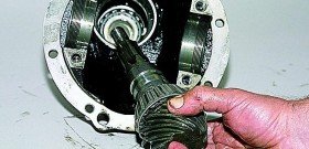
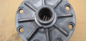

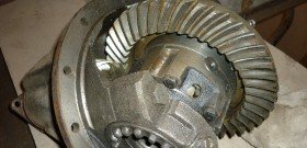

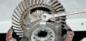

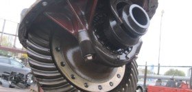

It is very easy to notice a gearbox malfunction, when cornering, a sharp deceleration or, on the contrary, acceleration, noise periodically occurs in the area of the rear axle... Do-it-yourself repair of the rear axle gearbox is not so difficult. Let's consider it on the example of a classic VAZ car. The first step is to drain the transmission oil from the rear axle gearbox. While the oil is draining from the housing, we disconnect the propeller shaft.
The next step is to dismantle the axle shafts and for this, first of all, we remove the rear wheels and brake drums. Then we unscrew the bolts securing the gearbox with the bridge. When installing a new gearbox, we use a sealant and do not forget about a cardboard gasket. Fill the gearbox with oil. The gearbox flange must fit snugly in place, as well as the bearings.
The rear axle reducer device itself is not so complicated, and, mainly, a hypoid look is found on rear-wheel drive cars. The whole difficulty lies in the fact that when removing the brake drums, a problem with rust can arise, and in some places the metal can be pressed very hard. But brute masculine power and a few tools will easily solve this problem.
If you are purchasing a new gearbox yourself, you should pay attention when buying that the same models can cost completely differently. This difference lies in only two letters OP (general bulkhead). This means that a factory check revealed a defect, and then the mechanism went to the bulkhead and is now in perfect order, but is sold at a reduced price.
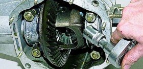
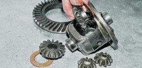

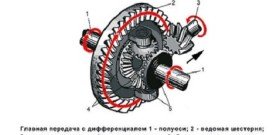



The rear axle gearbox is adjusted in cases where it began to bother you with a characteristic hum, which is heard already at a speed of 30 kilometers per hour (at KamAZ up to 80 kilometers per hour). The very reason may appear due to large constant overloads of the car or with constant driving with trailers, or maybe ordinary mechanical damage. Therefore, your next reaction will be a visual check of the unit.
Oil seals and flanges, bearings, satellites (star-shaped element in the differential) and their axles - all this is removed and inspected, in case of wear it changes. You can ask how all these parts should look in the car manual, if you have not had to hold them in your hands before. For VAZ, the replacement will be inexpensive, if you took up a foreign car, then first look around the current price lists.
Now that all the parts have been checked individually and are considered to be in good working order, we begin to assemble the gearbox. The drive gear will go first, to it - an adjusting washer, a spacer sleeve with bearings, a flange. Now you need to tighten the nut with a certain effort, for this you can use a special key with a built-in dynamometer, if there is none, you will have to constantly use a measuring lever with a steelyard. Those. every millimeter of the lever travel will have to be accompanied by measuring the pressure on it with the help of a steelyard, it is troublesome, but caution and accuracy are needed here. The nut must be tightened 1 Newton... In this case, the flange must be fixed, it is fixed with a specialized wrench with spacers, just suitable for the grooves of this flange.
Now we put the driven gear in its rightful place, i.e. into the differential housing and tighten the bolts. Now the direct adjustment of the backlash begins. After everything is installed, the nuts are tightened to the minimum stop, and the driven gear turns. After that, we look to see if it has a slight backlash, for this we swing it from side to side. The backlash should be, but small! This is a kind of reserve for heating the gearbox while driving, so that nothing bursts.
Now for the final stage. We check the distance between the bolts that hold the nuts we recently tightened. Use a vernier caliper, we need accurate numbers. Having measured the distance, we approach from the other side of the plane and now tighten the nuts, preferably by the same amount, for example, by 1 groove. We measure again the distance between the bolts, it should have changed by a small amount of about 1.5-2 mm. If so, it remains to check the gear for play, it is important that it remains the same as we just configured it. This completes the adjustment.
As an example, consider the parameters and assembly procedure for the rear axle reducer of the Moskvich-2140 car.
Main settings. Mounting dimension C - the distance from the end of the pinion gear to the differential axis - is theoretically 53.4 mm. However, when selecting a pair on a control machine, to ensure correct contact on the teeth and at the same time to obtain silent operation of the gearbox, the driven and driving gears are moved along their axes. Thus, the theoretical installation dimension is violated and its first amendment (deviation) is introduced.
In addition, the height of the pinion head is different (within the tolerance), and therefore, after measuring its nominal height, a second correction is made. The sum of these two corrections is recorded by the electrograph at the ends of the drive and driven gears as a general correction to the theoretical mounting dimension C.
If the correction number has a "+" sign, then it must be subtracted from the size of 53.4 mm, if the "-" sign, then add. The result will be the nominal mounting dimension of the pair. The allowed deviation can be 0.05. 0.02 mm.
The lateral clearance between the teeth of a pair of mating drive and driven gears is necessary due to temperature changes that occur during the operation of the unit, for the correct location of the contact patch of the teeth and due to the occurrence of errors in geometric parameters when processing gear teeth. For the main gears, the lateral clearance, measured normal to the tooth profile of the driven gear, should be 0.08. 0.17 mm. However, for each individual pair of gears, the difference between the largest and smallest clearances should not exceed 0.08 mm. The difference in the lateral clearance of two adjacent teeth should be no more than 0.04 mm.
The preload of the pinion bearings is created by the axial load that occurs when the pinion nut is tightened and is regulated by a spacer sleeve and shims that are installed between the inner rings of the front and rear bearings.
Measurements of the frictional moment are made after twisting the drive gear by 8.10 revolutions necessary to release the working surfaces of the bearings from lubrication and to acquire a working condition. You can check the friction moment using a special tool or a torque wrench or by hand, turning the flange mounted on the splines of the drive gear; some resistance to rotation should be felt, however, without causing undue tension in the hand.
Gearbox assembly. It must be performed in this order:
1. Press the outer rings of the front and rear bearings into the gear case, without shims, using mandrels under a press or hammer blows.
2. Press the inner race of the rear bearing onto the pinion with a drift under a press or hammer blows.
3. Insert the drive gear assembled with the inner ring of the rear bearing into the crankcase, put on the inner ring of the front bearing and install the crankcase on a stand with the stop of the drive gear end on a stand with a copper or bronze tip. Put on the slinger washer. Press on the propeller shaft mounting flange using a mandrel and a hammer, put on the washer and tighten the nut until it stops, thereby selecting the axial play of the drive gear (the gear should rotate when a little hand force is applied to the flange).
Rice. 154. Determination of installation dimension A in the gearbox housing: 1 - control mandrel, 2 - micrometer stand, 3 - support sleeve
4. Install the differential bearing caps in place in accordance with the marks, having previously inserted a control mandrel 1 (Fig. 154). Tighten the bolts of the differential bearing caps to a torque of 68.75 N * m, then using a micrometer stand 2, moved along the end of the drive gear, measure the distance b to the mandrel. Remove the differential bearing caps, take out the mandrel and the pinion gear, press out the rear bearing outer ring.
From the mounting dimension A, which is the sum of dimensions a and b, subtract the nominal mounting dimension C. The difference between the two dimensions A and C will represent the size of the required shim package, which must be installed in the crankcase under the outer ring of the rear bearing.
After installing the selected pack of gaskets in the crankcase, press the outer ring of the rear bearing again.
5. Insert the pinion gear into the crankcase with the telescopic control sleeve fitted on it. Install the crankcase on the assembly tool, resting the end of the pinion gear against the stand.
6. Using a mandrel, light hammer blows so as not to knock off the control sleeve, press the inner ring of the front bearing onto the drive gear, put on the slinger washer and press on the propeller shaft mounting flange. Put on the washer and tighten the nut, applying such a moment that, after turning the drive gear 8.10 turns, the moment of resistance to its rotation (preload) is within 1.5.3.5 N * m. Pull the pinion gear out of the crankcase.
7. Remove the inspection telescopic sleeve. Measure the difference in height between the telescopic and the working bearing spacer with a micrometer or an indicator with a stand: it is the size of the package of shims that must be installed together with the spacer on the drive gear between the inner rings of the front and rear bearings.
8. Insert the pinion gear with the spacer sleeve and the set of shims installed on it into the crankcase and re-install it on the assembly tool. Press on the inner race of the front bearing, put on the slinger washer, press on the propeller shaft mounting flange.
9. Put on the washer and tighten the nut with a torque wrench (tightening torque 145.160 N * m). Check the preload of the pinion bearings and be sure to check the mounting dimension again. If they do not correspond to the specified dimensions, it is necessary to amend the corresponding dimensions of the shim packs.
10. After final adjustment of the preload and installation dimension, unscrew the pinion nut and remove the flange. Press in the drive pinion oil seal using a mandrel until it stops. Before pressing in, the oil seal must be lubricated with engine oil. Install the flange, screw on and finally tighten the nut with a torque wrench (tightening torque 145.160 N * m), after placing a washer under it.
11. The maximum permissible axial play of the drive gear during the operation of the vehicle should not exceed 0.15 mm; it can be adjusted by reducing the package of shims installed between the spacer sleeve and the inner ring of the front bearing. If the bearings do not change, their preload should correspond to a frictional moment of 0.5 N * m.
12. Press the driven gear onto the gearbox of the assembled differential using a wooden or rubber mallet.
13. Install the assembled gearbox housing on a bench or in a vice.
14. Install the differential in the housing seats and screw on the bearing caps. Using an indicator fixed in the rack, check the runout of the end of the driven gear (allowable runout 0.08 mm).
15. Tighten the bearing cap bolts with a torque wrench, tightening torque 68. 75 N * m. Then, tightening the adjusting nuts with a special wrench without force, adjust the position of the driven gear rim so that the side clearance between the gear teeth was 0.10. 0.15 mm.
When checking the lateral clearance of the main gear, the indicator leg should rest on the tooth of the driven gear near the outer end in a direction perpendicular to its lateral surface, and the drive gear must be locked at the same time.
When rotationally swinging the driven gear in both directions, the gap on the indicator should be 0.10. 0.15 mm.
It is necessary to tighten the adjusting nuts so that the distance between the two covers of the split supports, measured at the upper points, increases by 0.10. 0.15 mm. In order not to change the position of the crown of the driven gear, tighten the two adjusting nuts with the same movement, but in opposite directions.
The side clearance should be 0.08. 0.17 mm on any gear tooth. The difference in the side clearance of two adjacent teeth should be no more than 0.04 mm, the largest difference in the side clearance for one pair of gears is 0.08 mm.
Reprinting of materials from this site is prohibited.
Rear axle reducer is a hypoid mechanical device, where there is a shank (drive gear), and the plane of the driven gear intersects, creating a torque character by means of angular transformation.
To perform such actions, we need: a strong thread, a torque wrench, adjusting rings, fine sandpaper and a vernier caliper.
The gearbox must be adjusted if a hum occurs at a speed of more than 30 km / h. The reason for this failure of the device, as a rule, is the prolonged operation of the car in difficult conditions. Constant overload, driving with a trailer.
Initially required to inspect reducer... It is necessary to brush all the elements, wash them in kerosene. If any defects are visible (damage to the gear teeth), then it is imperative to replace the damaged part. Take a look at the edges at the top of the teeth and the work surface - should be sharp. In the case of the presence of curvatures, nicks, it is worth changing the main pair. Minor defects are eliminated with fine sandpaper, and later polished.
During the assembly of the gearbox, install the spacer sleeve, a new flange nut, and a collar. If the device is assembled in an old crankcase, then calculate the change in the indicators of the drive gear, the adjusting ring. This is how you will determine the difference in thickness deviation between the new and the old model. Such designations are marked with marks "-", "+", the unit of measurement is hundredths of a mm, the data is present on the shaft at the drive gear. We clean the seats under the bearings with a fine sandpaper, a sliding fit should form. Then we press the outer rings of the bearings into the crankcase. Install the inner ring at the rear bearing into the crankcase. Now the flange from the drive gear, the inner ring of the front bearing is secured with a nut, until a moment of 1 kgf.m.
We install the crankcase with a level in a horizontal position. In order to clarify the format of the gap between the plate and the round rod, which is placed in the bearing bed, we will use a flat feeler. The resulting difference will reflect the thickness of the adjusting ring itself. We will use a piece of pipe that is suitable as a mandrel. Install the adjusting ring on the shaft. We mount the shaft itself in the crankcase. We form the parts in the following order: a spacer sleeve and an inner ring from the front bearing, then a collar, a drive gear flange. Using a torque wrench, we tighten the nut to a torque of 12 kgf.m. We tightly wind a strong thread on the neck of the flange, hooking a dynamometer to it. So we find out the scrolling moment formed at the drive gear shaft. The flange should turn with a force of up to 9.5 kgf, if new bearings are installed. If this is not the case, tighten the nut.
The tightening torque should not exceed 26 kgf.m. Otherwise, you have to disassemble the gearbox itself, replacing the spacer sleeve. Install the crankcase with bearings in the differential housing. The bearing cover is secured with bolts. If there is an axial play on the gears of the axle shafts, then use a thicker adjusting ring. The semi-axle gears must fit tightly. Here you can use a steel key (3 mm thick).
| Video (click to play). |
Then adjust the tension of the differential bearings, the gap present in the main pair. To check the distance at the covers, use a vernier caliper. We tighten the second nut until it stops. This gap between the covers will be slightly larger, by 0.1 millimeter. During the rotation of the first nut, e the gap is set in engagement. A slight rattling of the teeth will be accompanied by a correct repair. Then both nuts are tightened, the size of the mesh in the engagement is monitored. Tighten the nuts until the distance between the covers is no more than a standard 0.2 millimeters. Then the driven gear is turned three turns, checking the backlash in the engagement of each pair of teeth. We mount the locking plates.


