In detail: do-it-yourself trw rail repair from a real master for the site my.housecope.com.
Attention! Car service network of favorable prices. Camber check is FREE! No queues! Repair on the same day!
Download / Print topic
Download a theme in various formats, or view a printable version of the theme.
Time zone: UTC + 4 hours [Daylight Saving Time]
A year ago, I went through the TRW steering rack with a hydraulic booster. Now I decided to make a photo report. Something, I admit, has already been forgotten, but in general, the scope of work and the approximate progress of its implementation with possible jambs will be clear.
The need for a bulkhead is ripe due to the fact that around the upper oil seal of the rack shaft (on which the steering propeller shaft is fixed) it is damp. Obviously, dirt got under the gland and ate the gum of the gland, because of which it began to undercut.
He began by ordering a steering rack repair kit in the store. I can't tell you the set number - the seller was looking for it. Photo 6909 shows this set - manufacturer DP Group, and the only identifier on the package is “xdpg-ss3123”. Maybe this is the number.
So let's get started.
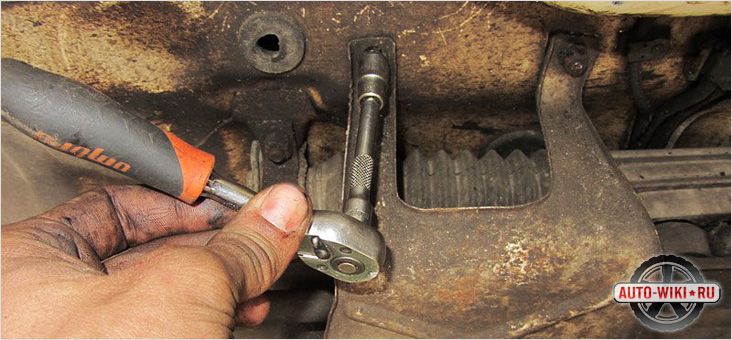
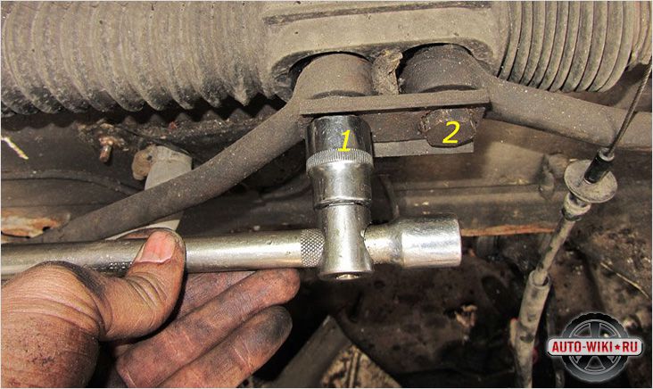
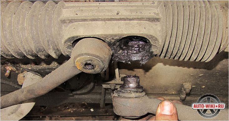
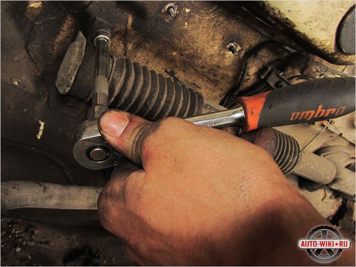
1. First you need to remove the rail from the car. Personally, I would recommend first unscrewing the steering rods from it for this. When I removed the rail, the engine was also removed, and it was easy to get close to the rail, but despite this, the steering rods still interfered with its normal removal, so I recommend disconnecting them. To do this, it unscrews the steering tip from the steering rod, and the rod itself, if there are no turnkey slots on it (on my old rods, there were none. On new, purchased ones, there were), you can use such a clamp, as shown in photos 5748 and 5749. The photo was taken when the left rod was removed - it is more difficult to get to it than to the right one, and I could only move it with the help of such a clamp - no key could get there. However, such a clamp can be bought at any car dealership, so no problems should arise.
| Video (click to play). |
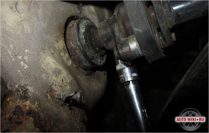
2. Inside the passenger compartment, unscrew the bolt 10, securing the steering wheel gimbal to the rack shaft, remember how to put it back - it will be possible to do it only in the same position. It is better to practice a couple of times to move the L-shaped latch (it will be seen on the spot what we are talking about) and snap it back. It's just that when I put it back after the bulkhead, I had to suffer pretty much before I found the original position. Next, remove the plastic plug with a hole through which the rail shaft enters the passenger compartment, unscrew the vibration damper from the rail shaft itself - seen in photo 6905, this is already in the engine compartment again (be careful, otherwise if you break the latches, you will have to glue back on the glue)
3. Unscrew the 2 bolts securing the rail to the body. One is visible in photo 6905. The second is to the left. I remember that something prevented the normal pulling out of the second bolt after unscrewing it. Therefore, when installing it back, I shortened it a little. I don’t remember exactly - I was running into something, it seems. But this is a common ordinary problem - it is solved on the go with a personal examination.
4. The steering rack is free - the tubes are unscrewed (I did not write about this separately), the steering rods, the vibration damper are removed from the shaft, the two bolts securing the rack to the body are unscrewed - we remove the rack.
Added after 3 minutes 25 seconds:
THIS IS THE FIRST TIME AT THE FORUM, WHILE I UNDERSTAND WHAT TO WHAT, SO DON'T CREATE
just DO NOT WRITE in big letters.
Added after 37 seconds:
the stamp on the rail is a blue plate, it is visible if you look from below under the car between the left wheel and the gearbox, I have “ZF” marking on it
Added after 1 minute 1 second:
Added after 1 minute 3 seconds:
after removing the panel under the steering wheel, the front end is raised, the wheels are level, the steering wheel is locked
Added after 52 seconds:
Added after 2 minutes 33 seconds:
we get to the bolt under the panel, on one side it is turnkey for 13 to mine, and on the side of the arrow drawn there is a polyhedron, it is in order to turn the eccentric of the bolt in order to get the bolt itself out of the groove
Added after 1 minute 5 seconds:
Added after 1 minute 5 seconds:
that's what we got, the shaft for which I hold on is better to tie it with a wire to the panel so as not to interfere
Added after 56 seconds:
Added after 1 minute 45 seconds:
aaaaaaaaaaaaaa, I forgot, in the previous fig. remove the rubber sealing ring.
now we unscrew the tubes numbered 1 and 2
Added after 55 seconds:
Added after 1 minute 7 seconds:
after draining the liquid from the barrel, the hose is clamped with a clamp (arrow without a number)
Added after 1 minute 15 seconds:
Added after 3 minutes 34 seconds:
running ahead, we will get the rail through the left wheel (the wheels must be removed, this is understandable
Added after 1 minute 26 seconds:
Added after 6 minutes 38 seconds:
we unscrew the steering tips on both sides, do not confuse them, they are visually the same, but if you look at the markings (I had it) then one had 60 and the other had 61 numbers, it’s better to sign them and count on which we turn out the number of turns, so that then do not adjust wheel alignment.
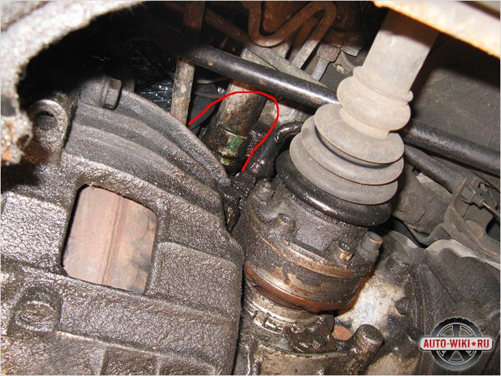
Then we take tube 1 through the free space under the wing, having previously squeezed it out of the power steering pump (in Fig. 3 it is marked with an arrow 1, there is 22 head, you can see. on her
Added after 1 minute 3 seconds:
Added after 59 seconds:
Added after 4 minutes 36 seconds:
in Fig. 7 and 8, arrows show the location of the bolts for fastening the rail to the top (in general, it is fastened with three bolts), the third bolt is located from the bottom (Fig. 7, about 10 cm approximately in the direction of the knob, if you stick your hand under the bottom then you can feel it), in my opinion for these bolts the head is E 16, I don't remember exactly
Added after 6 minutes 38 seconds:
unscrewing the three bolts securing the rail, removing the tips, the tubes going to the rail from the pump, we try to get it through the prepared left side. (just don't swear [-X)
Added after 52 seconds:
Added after 31 seconds:
Added after 1 minute 49 seconds:
Added after 3 minutes 2 seconds:
then, first of all, lightly punch with a center punch on this disc and on the rail along a dot (it is for adjusting the backlash), and when you unscrew it, count the number of revolutions, so that later, when assembling, the punched points coincide.
Added after 1 minute 19 seconds:
then we wash the rail clean, so that there is no dirt, etc. "hydraulics loves cleanliness."
Added after 55 seconds:
Added after 2 minutes 21 seconds:
after we unscrewed this thing, which we had marked with a punch, we get out the "piston" and the plastic under it, on the piston we also marked the points as it stood with a punch.
Added after 45 seconds:
Added after 7 minutes 52 seconds:
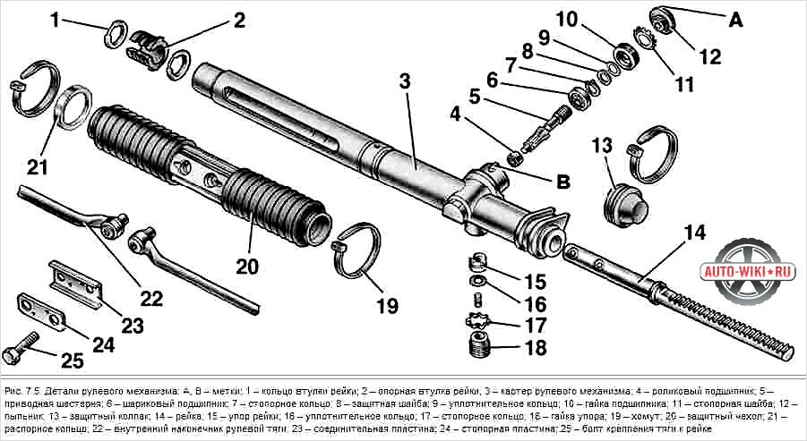
after we unscrew the nut at the bottom of the worm, we take it out, I marked three white rings on it with arrows, there are still casino rings under them, we take them off (there are four white rings in the kit, I immediately thought that one was spare, and then I saw that three the same, and the fourth with small “grooves” along the edges (sweep, you need to take a closer look), because these three are the same and go to this worm, and the fourth to the rail itself (I’ll tell you later when I’ll tell you until this moment), we put them, not forgetting about the little black rubber bands that also come in the kit, and during the assembly we lubricate the whole thing with the power steering fluid during assembly.
Added after 1 minute 2 seconds:
Added after 43 seconds:
we take out the rail through the end "A"
Added after 1 minute 26 seconds:
Added after 6 minutes 4 seconds:
after taking out the rail, remove the rod No. 1, change the oil seal in it, (there will be a bushing at its end, it is not in the repair kit, neither on this nor on the second side), we change rubber rings on the rods 1 and 2 (there are a lot of them in the repair kit, on every little thing, do not be alarmed at once, you will understand everything in the process, I didn’t expect from myself, and it turned out the same.), after we remove these two rods, there is a ring on the rail shaft itself, on it there is THIS FOURTH WHITE SLEEVE ABOUT WHICH I WRITTEN WITH GROOVES ON THE SIDE, THERE IS THERE HER AND WE PUT IT.
Added after 1 minute 35 seconds:
Added after 4 minutes 53 seconds:
in this fig. the location of the second coin is marked on the inside, it is closer to it, it is not there alone, there is also a plastic washer and a sleeve, do not confuse the sequence of their location, the whole thing goes to the “A” side. I used a head (I don't remember which one, either 21 or 22 or 24, and I put several extension cords on the head (I had two sets of keys at hand) and everything worked out easily). try, be smart.
Added after 1 minute 18 seconds:
Added after 4 minutes 31 seconds:
the third oil seal becomes on the worm, to replace it, you need to remove the lower small bearing of the gear shaft to get to the oil seal, which sits under the middle bearing of the gear shaft, does not sit tight, and the oil seal and bearing, after extruding, we press the new oil seal to the end, but with the bearing do not overdo it, it is not completely pressurized, although as far as I remember there are different diameters at the holes for the oil seal and for the bearing, but the difference is very small, so it is better to measure how deep it sits before removing the bearing so that it sits so much later, in my opinion the bearing sits at a depth of 58 mm. So, see "in place".
Added after 49 seconds:
Added after 6 minutes 30 seconds:
but this design, just in case, for you, when I knocked the oil seal out of the middle, it crumbled when it fell out
Added after 1 minute 13 seconds:
Added after 36 seconds:
this is what the rem kit looks like
Added after 55 seconds:
Well, that's all, the assembly is in reverse order, all the parts are first lubricated with power steering fluid and then put into place.
We shove the rod, its sleeve, put the locking ring of the rod sleeve, then we put the gear shaft, while twisting both the shaft and the rod, we put the locking ring of the gear shaft sleeve, press in the lubricant, I used a regular lithol, tighten the bolt at the bottom of the shaft into the hole of the pressure clamp, tighten the lower plug and we knock the edge so that it does not unscrew, we assemble the clamping mechanism, not forgetting to combine the marks that we put.
put the tubes in place, confuse them at the bottom, although if you accidentally bent it is possible, it is better to note who is where, and do not tighten too much, aluminum is still
Repair of the TRW / CAM steering rack
Information is shared by alex.ekt + my addition.
Complete TRW Steering Rack Repair Report. If you have a rail as in the picture.
... then my information will be useful to you. I will not talk about the process of removing the steering rack from the car.
Before disassembling, you must purchase the repair kit shown in the following figure:
It includes:
1) clamps,
2) oil seals rails,
3) rubber and fluoroplastic rings on the rail,
4) inner shaft seal,
5) 4 PTFE shaft rings,
6) outer oil seal and shaft boot,
7) an O-ring of a plastic sleeve.
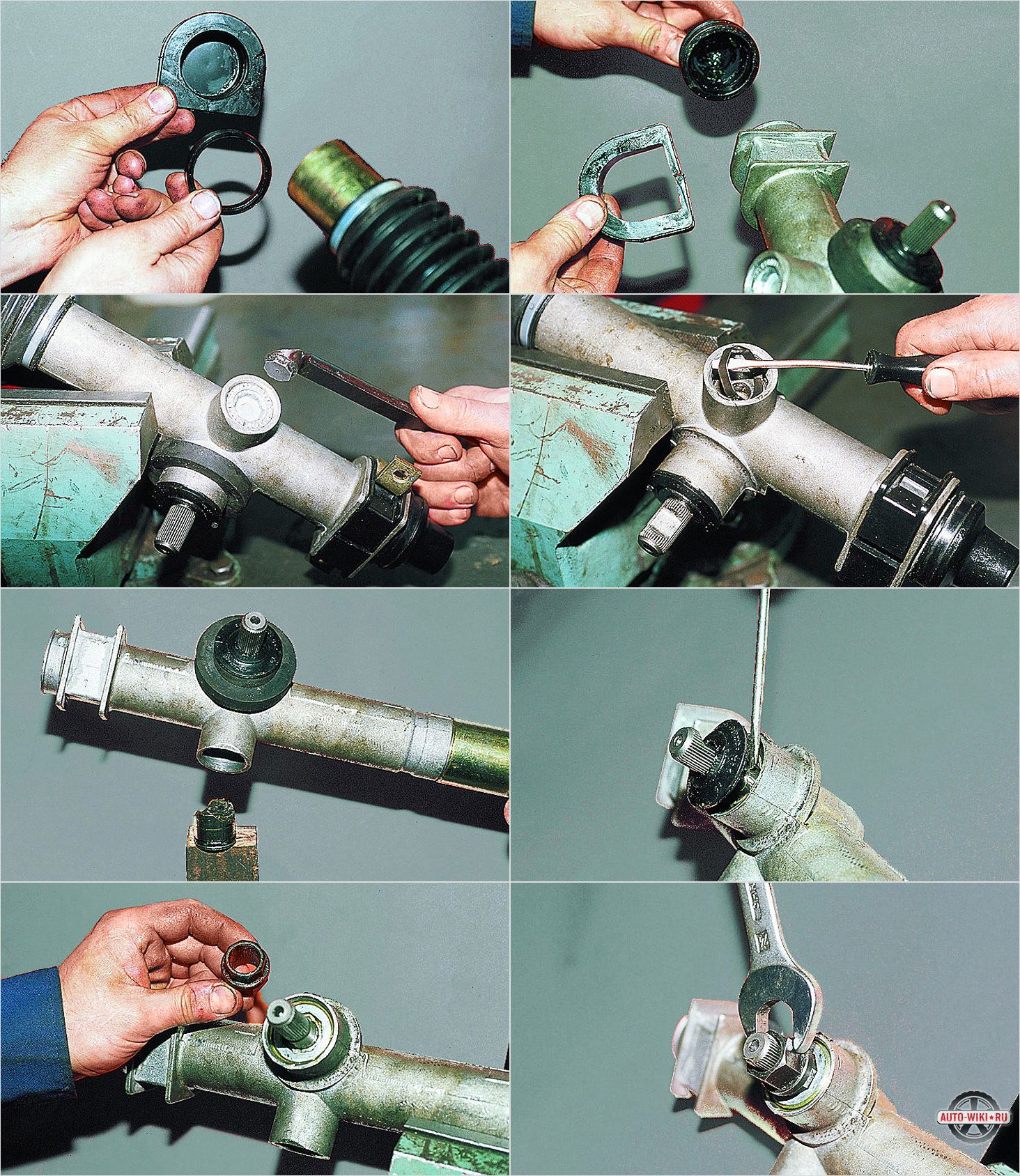
We start repairing. The rack is removed, cleaned of dirt and oil and is ready for disassembly. We remove the corrugated anthers and unscrew the steering rods:
Using a special wrench (made from a suitable tube), loosen the adjusting nut:
Using a screwdriver, pick out and remove the boot from the shaft:
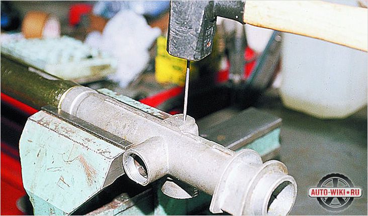
Using a punch or a screwdriver, we knock out the plug:
... and knock out the shaft from the side of the nut using a soft punch:
ATTENTION. Before knocking out the shaft, we notice its position relative to the rail. Remove the oil seal, plastic sleeve and PTFE rings from the shaft.
While repairing my rack, the aforementioned plastic bushing mounted on top of the “worm” shaft needed to be replaced, instead of it a needle bearing from the steering rack was installed. if memory serves from the Passat B3.
We take out the inner shaft seal. If you wish, you can remove the bearing retaining ring and take it out (I did not remove it).
Due to the fact that the bearing had a significant backlash, I replaced it with a bearing of a suitable size from a domestic manufacturer.
You can also knock the pin out of the shaft and disassemble it, but this is not necessary, there is simply nothing to break there.
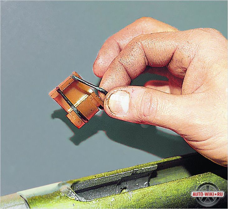
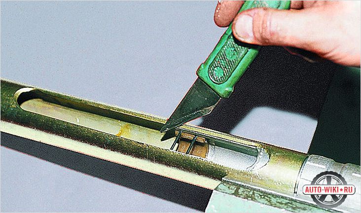
We proceed to dismantle the rail. We turn the caprolan end sleeve counterclockwise, the retaining ring will be unscrewed through the oval hole.
After the retaining ring comes out completely, you can dismantle the rail. To do this, simply pull out the rail towards the sleeve. We take out the rail along with the bushing and the oil seal:
Remove the bushing, oil seal, PTFE and rubber rings. I took out the inner oil seal with an ordinary wire hook, but I did it carefully. We take out the inner oil seal and the support plastic sleeve. That's it, the disassembly stops there.
We proceed to troubleshooting and assembly. All items are carefully washed. We examine the rail. The working surface should be free from defects and scratches.
Even if you have minor seizures and shells like in the following photo.
... then grinding can help, because of this sink I had to grind the rail for 1.5 hundred parts in places, the next almost 3 years of operation, before the sale of the car, I did not experience any problems with the rail, the new owner too. As for the end caprolan bushing, it was worn out and was a source of knocking, the rack was pushed in the bushing stretching the oil seal, it was justified for me to grind it out of the caprolan on a lathe.
To check the shaft, it is necessary to carefully clamp the working splines of the rack, and check the elastic displacement of the upper part, turning right and left at an angle of 5 degrees relative to the middle position. This turn in one direction or the other ensures the performance of the steering rack. If this is not the case, then it is necessary to additionally disassemble the shaft by knocking out the pin. As I said, there is nothing to break there.
We put in place the inner support sleeve and the oil seal in the rack housing. Press in the oil seal using a head of a suitable diameter with an extension. We change the rubber ring and fluoroplastic on the rail, change the rubber ring on the plastic sleeve (Photo 12).
We grease everything with oil and put it in place. We put the retaining ring of the plastic sleeve in place by turning the sleeve clockwise, cover the oval hole with a sealant. If the shaft bearing was removed, then we put it in place and put the bearing retaining ring.
ATTENTION. While the shaft is without PTFE rings, it is necessary to try to put it in place. The fact is that when the shaft is installed in place, it scrolls counterclockwise by a certain angle. Therefore, before installation, it must be turned clockwise by this angle. This angle must be remembered!
We install the inner shaft seal in the rack housing. We put fluoroplastic rings on the shaft. The rings were preheated on a battery. We put it neatly, but confidently. The rings are strong (try to tear the old ones with your hands). After installation, the rings stretch and must be squeezed. To do this, we make a crimp of a suitable diameter from a tin (can). I crimped and fixed the crimp in a vice for 5-10 hours to give the rings their original condition. After compression, grease with oil, turn the shaft to the required angle and put it in place, gently tapping with a hammer.It is advisable to do this operation the first time. Fluoroplastic rings do not tolerate several times of dismantling and installation. We tighten the shaft nut.
We put grease and put a plug:
We put in place the plastic shaft sleeve, press in the oil seal, put the retaining ring (Photo 6).
We put a boot on the shaft and press it into place. Lubricate the rail. We adjust the gap between the rail and the shaft (Photo 4).
We fasten the steering rods, fix them with a core and put on the corrugated anthers. That's it, the rail is ready to be installed on the machine. We put it on, connect the hoses, fill in the liquid, pump the system and enjoy the work of the power steering.
The hydraulic power steering gear (steering rack) is responsible for organizing the turns of the vehicle. This mechanism is an integral part both for cars with hydraulic power steering and for cars without hydraulics. The steering column serves as a connecting element between the steering wheel and the wheelbase, so its role in the safe operation of the vehicle cannot be overestimated.
The parts of the steering rack wear out quickly enough, because take on the main part of the load that is transferred to the car during cornering, when hitting any type of obstacle, when the wheelbase hits potholes and holes in the roadway. Do-it-yourself steering rack repair may often be required.
To prevent failure of the steering rack, a technical inspection of the vehicle should be periodically carried out, which allows you to identify all faults at an early stage.
The main signs indicating the appearance of deviations in the operation of the gearbox:
- The presence of knocks in the gearbox, transmitted through the steering wheel of the vehicle;
- An increase in the effort that the driver needs to apply to the steering wheel to turn it;
- Extraneous noise arising during the operation of the hydraulic booster pump;
- The presence of a backlash in the steering rack, which is felt when turning the steering wheel;
- Traces of oil leaking from the hydraulic power steering.
Any of the listed symptoms signals a malfunction that must be eliminated immediately. Lack of timely work can adversely affect the operational life of the mechanism, up to its complete failure.
If a problem is found, the car can be handed over to a car service specialist or the steering rack can be repaired with your own hands. It should be noted that self-elimination of defects requires certain knowledge about the device of the vehicle and some tools necessary for disassembling the steering rack.
To fully repair the steering rack, you should have the following spare parts and tools on hand:
a special repair kit consisting of all the parts necessary for the steering rack;
- corrugation;
- gear shaft;
- bearing;
- lubricating mixture.
- octahedron key at 17;
- tools for mounting and dismounting bearings;
- set of wrenches.
For the highest quality repairs, it is advisable to use a flyover or inspection pit.
First of all, the vehicle should be driven onto an overpass or inspection pit, after which, with the help of jacks, the vehicle should be raised and the engine protection (if present) and wheels should be dismantled. Next, you need to remove the heat-insulating plate of the gearbox and unscrew the nuts of the ends of the steering rods, which are knocked out of the ears with a hammer. The next stage consists of disconnecting the pipeline followed by a liquid removal procedure. To do this, you need to start the car engine, and then make several turns with the steering wheel in different directions. The process is completed by removing the fasteners located on the hydraulic power steering gearbox. After dismantling, the mechanism is securely fixed in a vice and cleaned of dust and dirt, which inevitably accumulate on parts during the movement of the car.
Photo instructions for dismantling:
- Removing the rubber boot.
- Dismantle the intermediate shaft by removing the lock nut holding the part.
- Removing the lock nut securing the rack shaft clamping cup.
- Dismantling the shaft with bearing. To do this, the main shaft system is knocked out of the pre-fixed intermediate shaft with gentle blows.
- Dismantling the adjusting unit.
- Removing the adjusting glass.
- Removing the pressure piston.
After the completion of work on the disassembly of the steering rack, all the constituent elements of the mechanism are thoroughly washed from the oil and dirt deposited on them. Then the parts are subject to a thorough visual inspection for the presence of mechanical damage arising during the operation of the vehicle. Parts with serious defects must be replaced with new ones. In some cases, due to severe damage, it is advisable to completely replace the steering rack. Assemble the steering rack in the reverse order.
There are no significant differences between repairing the steering rack of cars with and without hydraulic power steering. Only bushings and compositions of fluids used to lubricate parts of the mechanism will be different.
After carrying out all the above-described work, it is recommended to carry out the diagnostic procedure for wheel alignment.
The total time it takes to repair the steering rack varies from two to three hours. These repair work refers to work of an average degree of complexity, which, with certain knowledge and skills, it is quite possible to carry out even a novice car enthusiast who has patience and perseverance in achieving a specific task.
Useful video for repairing the steering rack VAZ 21099:
Before assembly, check the housing for contamination (residues of varnish, shavings, dirt) and clean thoroughly if necessary.
- Instruction. During assembly, be very careful about cleanliness!
- Check the cylinder guide for scoring and other damage. If the seizure is significant, replace the entire steering gear.
- Check the toothed rack for scoring.
- Lubricate O-rings with hydraulic oil before installing.
- Check that the inside of the valve body -2- is absolutely clean.
- Press in the valve body O-ring as far as it will go.
- 1 - the O-ring
The sealing bevel -arrow- points upwards towards the tool. The installation site of the O-ring in the valve body.
The bevel of the sealing ring -arrow- is directed upwards.
For better presentation, Fig. the top of the valve is shown in section.
Installing the internal o-ring of the toothed rack
- Place O-ring -1- on the tool.
- Lubricate O-ring -1- with oil.
- Press O-ring -1- into the cylinder tube so that the groove -arrow- on the tool is covered with the edge -arrow A- in the housing.
Installation location of the sealing toothed rack.
The O-ring back-up ring points towards the valve body.
- 1 - Support ring
- 2 - the O-ring
- 3 - Valve body housing
For better presentation, Fig. the body is shown in section.
Replace the rack immediately if corroded spots or deep seizures are visible on the rack.
When delivered as a spare part, please consult with.
No conclusion can be made as to whether the rack is damaged by force, such as an accident, on the basis of such a visual inspection.
If slight scuff marks -arrows- are noticeably noticeable on the toothed rack, the depth of which is such that they can be removed with sanding paper (grain size 350 ... 600), the rack can be reused.
- Sand the toothed rack radially with sanding paper. (Only for shallow seizures).
- Check the chamfers at the ends of the toothed rack for damage and, if necessary, remove with a whetstone and / or sanding paper.
- 1 - a toothed rack
- 2 - Sanding paper (grain size 350 ... 600)
- 3 - Protective jaws of the vice
If the removed rail will be used, check the o-ring for grooves (visual inspection). If there are visible or significant grooves, replace this O-ring and the O-ring behind it.
- Lubricate the toothed rack with oil (corrosion protection).
Replacing the gear rack O-ring
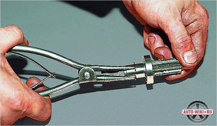
- Use a pliers to compress the O-ring with light force.
- Press off this ring and O-ring.
- A - Spacer pliers (universal)
- 1 - a toothed rack with a piston
- 2 - the O-ring
- 3 - the O-ring sealing ring
Installing the O-ring on the rack piston.
- Push the mounting sleeve onto the toothed rack.
- Place the O-ring on the tool and insert into the piston groove.
- Lubricate the O-ring with oil, place on the tool and insert into the piston groove.
- Clean the rack and grease (remove old grease between the teeth).
- Lubricate rack teeth with steering gear lubricant -A0F 063 000 04-.
- Push the protective tube onto the toothed rack -1- as far as it will go.
- Remove excess grease completely.
This grease must not get into the oil circulation!
- Lubricate the rack piston and protection tube with hydraulic oil.
- Insert guide bush -3315 / 22- into housing.
- Insert the toothed rack into the housing.
During insertion, make sure that the O-ring is pressed into the groove of the piston without jamming.
- Slowly insert the toothed rack into the housing.
- Remove protection tube -3315 / 13- from toothed rack.
- Align the rack gearing in such a way that it is directed towards the gearing of the pinion.
- Screw assembly bush -3315 / 18- onto the toothed rack and lubricate with oil.
- Carefully insert its guide -1- through the toothed rack into the housing until it stops.
- If not already, slide the toothed rack fully into the housing.
- Insert the lock washer into the body and press in until the groove in the lock washer is visible in the elongated hole in the body.
- Insert circlip into hole in circlip -arrow-.
- Retract the safety wire by turning the lock washer. (After retraction, tighten the lock washer by another 1/2 turn).
- 1 - Safety wire
- - in a repair kit not in the form of a ring, supplied as a straight wire.
- 2 - Pliers (universal)
- Carefully press in the lower ball bearing of the valve body until it stops.
- Lubricate with steering gear grease -A0F 063 000 04-
The ball bearing must not be tilted when pressing it in.
- Screw assembly drift -3315 / 15- onto the valve body.
- Lubricate the valve body with oil and carefully insert it by hand into the valve body. (Observe the position of the toothed rack).
Make sure that the O-ring in the housing is not damaged by the gear teeth!
- Cover the toothed rim of the valve body with electrical tape (eg plastic tape) to protect the O-ring. Avoid creasing.
- Install the valve body upper roller bearing. (The inscription on the roller bearing points upwards).
- A - Electrical tape
- B - Valve body
- Press in O-ring until the groove in the circlip is visible in the housing.
- Insert the circlip.
- Remove the adhesive tape / tape.
- Unscrew assembly punch -3315 / 15-.
- Screw on the hexagon nut of the valve body and tighten (30 Nm, hold with a 14 mm spanner).
- Screw in the screw plug (40 Nm).
- Lubricate stop with steering gear grease -A0F 063 000 04-
- Insert the stop and the spring into the body.
- Screw in the lock nut with the adjusting screw.
- The marks -arrow- of the adjusting screw and locknuts must match after tightening. If a new rack was installed, adjust the power steering with a new rack.
- Adjust the steering gear when installed.
- Clean the adhesive surfaces in the area of the elongated hole with a solvent (eg nitro thinner -L 160- or alcohol).
- Fill elongated hole with sealant -AKL 450 005 05-.
- Cover the hole with electrical tape -1-.
If the toothed rack has been replaced, adjust the steering gear before installing the transverse rods.
Install the cross rods.
- Clamp the toothed rack in a vice and tighten the transverse link.
Instruction. Apply protective jaws of the vise, check them for cleanliness; for example, carefully remove metal shavings or the like.
Place of installation of the corrugated cover
- 1 - Corrugated cover
- 2 - Housing
When installing the cover, make sure that the flange -arrows- of the cover are in contact with the body.

Video (click to play). - 1 - the Clamp
- 2 - the Equalizing tube
- 3 - Corrugated cover
- a - about 90 °
- Press off clamp with pliers -V.A.G 1275-.
- Press off clamp with pliers -V.A.G 1275-.
- Press in O-ring until the groove in the circlip is visible in the housing.
- Carefully press in the lower ball bearing of the valve body until it stops.


