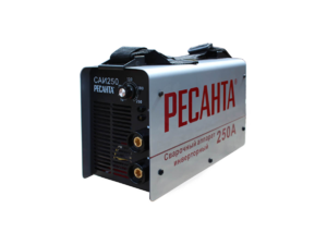
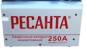
In detail: do-it-yourself repair of resant sai 250 from a real master for the site my.housecope.com.
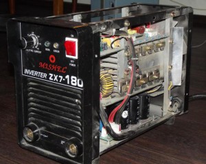
Once the Resant SAI 250PN welding inverter fell into my hands. The device, without a doubt, inspires respect.
Those who are familiar with the device of welding inverters will appreciate the power of the electronic filling.
As already mentioned, the filling of the welding inverter is designed for high power. This can be seen from the power section of the device.
The input rectifier has two powerful diode bridges on the radiator, and four electrolytic capacitors in the filter. The output rectifier is also complete with: 6 dual diodes, a massive choke at the output of the rectifier.
three ( ! ) soft start relay. Their contacts are connected in parallel to withstand the large current surge when welding starts.
If we compare this Resanta (Resanta SAI-250PN) and TELWIN Force 165, Resanta will give him a dashing head start.
But, even this monster has an Achilles heel.
The cooling cooler does not work;
There is no indication on the control panel.
After a cursory inspection, it turned out that the input rectifier (diode bridges) turned out to be in good order, the output was about 310 volts. Therefore, the problem is not in the power section, but in the control circuits.
External examination revealed three burned out SMD resistors. One in the gate circuit of the 47 Ohm field-effect transistor 4N90C (marking - 470), and two at 2.4 ohms (2R4) - connected in parallel - in the source circuit of the same transistor.
4N90C bipolar transistor (FQP4N90C) is controlled by a microcircuit UC3842BN... This microcircuit is the heart of the switching power supply, which powers the soft-start relay and the integrated stabilizer at + 15V. He, in turn, feeds the entire circuit, which controls the key transistors in the inverter. Here is a piece of the RESant SAI-250PN diagram.
| Video (click to play). |
It was also found that there is also a resistor in the power circuit of the UC3842BN (U1) ShI controller in the open circuit. In the diagram, it is designated as R010 (22 ohm, 2W). It has the reference designation R041 on the printed circuit board. I will warn you right away that it is quite difficult to detect a break in this resistor during an external examination. A crack and characteristic burns can be on the side of the resistor that faces the board. This was the case in my case.
Apparently, the cause of the malfunction was the failure of the UC3842BN (U1) ShI controller. This, in turn, led to an increase in the consumed current, and the resistor R010 burned out from a sharp overload. SMD resistors in the FQP4N90C MOSFET circuits played the role of a fuse and, most likely, thanks to them, the transistor remained intact.
As you can see, the whole switching power supply unit on the UC3842BN (U1) has failed. And it feeds all the main units of the welding inverter. Including soft start relay. Therefore, welding did not show any "signs of life."
As a result, we have a bunch of "little things" that need to be replaced in order to revive the unit.
After replacing the indicated elements, the welding inverter turned on, the display showed the value of the set current, the cooling cooler clinked.
For those who want to independently study the device of the welding inverter - the complete schematic diagram of "Resant SAI-250PN".
Let's take a look at one of my "clients" today, namely the "Resanta - SAI 250 PROF" welding inverter. Why a client, because the malfunction with which he came to me on the desktop was the most frequent in this kind of welding machines - secondary power supply, or it is also called the "standby source".
You can order the elements listed in the article for repairing the Resant welding inverter - SAI 250 PROF on Ali:
1) Shim controller SG6859 - https://ali.pub/2pd1gz
2) Field effect transistor SPD06N80C3 - https://ali.pub/2pd1qb
3) Controller TOP 224 - https://ali.pub/2pd244
So, this friend is assembled in this welding machine for shim controller SG6859 and field-effect transistor SPD06N80C3 there is no need to list the strapping and everything else.
What is the salt you ask. Here's the thing. When a field worker punches it, he pulls the PWM controller and a small part of the harness with him. Finding the parts I need on the radio market is very difficult. But thank God we have Chinese (what would we do without them) that's where I ordered them. The cost is ridiculous, but the terms are long, which did not really suit me. But this also has its advantages.
The person who brought me the welding machine, due to the rather long delivery time for the original parts, offered me to buy it back. We bargained and I bought a damaged "friend" SAI 250 PROF from him for 3500 rubles. Of course, I knew that it cost me 450 rubles to repair it. But knowing the price that it was worth, I did not think for a long time, took out the cherished ever-wooden and settled with the person and proceeded to repair the Resant welding inverter
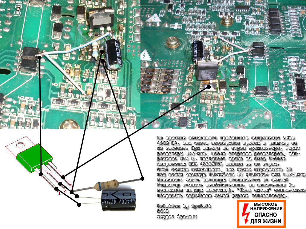
Without waiting for the details to arrive (my hands were itching), without hesitation, I figured out a small alteration from the Internet and everything worked out for me.
The alteration is as follows:
We take a microcircuit TOP 224 (223, 204, 203)
- We remove the field-effect transistor;
- We remove the PWM controller;
- We unsolder the emitter of the optocoupler U8 (participating in the feedback with the PWM) and chorus it to the "control" pin TOP 2xx; We connect the collector to the "+" supply PWM via contact No. 5 -VDD. You can take it from the positive terminal of the C30 capacitance;
- Drain or (Drain) to the place of the drain of the former SPD06N80C3 (the largest site);
- Source to place of source SPD06N80C3;
- Solder the capacitor between the source and the gate (control) 47 uF - 50V, "-" to the source.
- Instead of resistances 1.3 Ohmx3, we solder the resistance 6.8 Ohm.
That's all. We launch it and everything works.
Here is a photo of the revision (from the Internet) not my invention:
Below is the second option. Personally, I did it first.
So, after some minor manipulations, I have a SAI 250 PROF welding machine from RESANT. The device is very good, decent and certainly worth the money. Amendment - the money that I paid for it - 3500 rubles.
Datasheet on TOP 22x (1,2,3,4,5,6,7) - Download
Passport for RESANTA SAI-250 PROF - Download
Welding machine diagram RESANTA SAI-250 PROF - Download
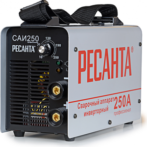
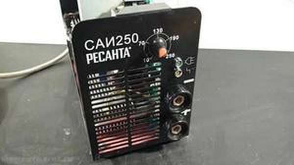
The considered device for welding Resant SAI is made in a steel case. On the outer part of this body there are power connectors for connecting welding cables, two indicators ("Mains" and "Overheating"), a regulator for selecting the characteristics of the welding current. Also in the case there is a special hole through which hot air is removed from the device. It is part of a forced ventilation system that protects the inverter from extreme overheating during operation.
The Resant Sai inverter also has one more protection system, it automatically turns off the device in cases where power cords are short-circuited. Moreover, the corresponding indicator on the front control panel starts blinking.The inverter is distinguished by the presence of several important functions that are often used during operation:
Hot start guarantees fast and high-quality ignition of the welding arc due to an increase in the level of the welding current (the worker does not need to do anything, the current increases in automatic mode). And the anti-stick mode, on the contrary, reduces the welding current if, during the ignition of the electric arc, adhesion of the welding wire (electrode) is noted. Then, when the adhesion is removed, the welder automatically restores the welding performance on its own.
You can use rods for welding up to 6.0 mm. The welding current in the device can be adjusted up to 250A. It is also important that the device is able to withstand rather heavy workloads for a long time. This property positively distinguishes its scheme of work from other devices, which are found in abundance on the windows of specialized hardware stores.
Idling Resanta SAI's welding device operates with a voltage of 80 Volts. The durability of the device at a fairly high power is ensured in its circuit by the design of modern high-quality IGBT transistors. In addition, this welding inverter has a high degree of protection - IP 21 protection level.
One cannot fail to mention the compactness of this welding machine, as well as its excellent mobility. Equipped with a handle for carrying the device, it makes it easier to carry it around the territory of the site where the construction is taking place. Also, consumers note the accuracy and simplicity of setting up the Resant sai welding inverter. At the same time, the specified indicators are guaranteed to retain the established data even in cases where the electrical network does not differ in the stability of its voltage indicators.
Specifications of the Resant SAI apparatus of interest to us are as follows:
- maximum current consumption - 35 Amperes;
- load duration at 250 Amperes - not less than 70%;
- welding adjustment interval - 10-250 Amperes;
- working temperature range of the environment - -10 / + 40C;
- arc voltage - 30 Volts.
If necessary, this device can be connected to the equipment of a generator that runs on gasoline. It is best to choose a generator with a power of more than five kilowatts.
Attention! When choosing a welding electrode (the electrode can be no more than 6 millimeters in diameter), it must also be taken into account that the welding current decreases when the input current decreases.
Put the regulator for minimum welding current, then you can connect the inverter to the power grid, and then turn it on. The required level of welding current must be selected based on the indicators recommended by the manufacturer of Resant SAI:
- 200-300 Amperes - electrode diameter 6 millimeters;
- 160-200 Amperes - 5 millimeters;
- 130-160 Amperes - 4 millimeters;
- 90-140 Amperes - 3.2 millimeters;
- 60-90 Amperes - 2.5 millimeters;
- 50-60 Amperes - 2 millimeters;
- 25-50 Amperes - 1.6 millimeters.
After welding, the current is set to the minimum value by means of the regulator, the inverter is turned off (first by a switch, and then from the mains). You also need to disconnect the electrical holder and grounding cord from the device.
Before switching on, the device must be kept at a positive air temperature for several hours. Otherwise, condensation may form in it, which may damage the inverter. It is strictly forbidden to operate the device in cases where its welding cords or the wire connecting to the mains are deformed (even slight).
Near a switched on welding machine, you must not process metal and steel parts using grinders, electric jigsaws and similar equipment, during which metal dust appears... Dust can enter the cabinet and damage the inverter. In addition, it is forbidden to operate the unit in open areas in the rain or in rooms with high humidity.
Before operating the Resant SAI inverter, it is imperative to study the "Safety Rules for Users of Electrical Devices" and "Rules for the Operation of Household Electrical Installations". During operation welding machine you need:
- create access to fresh air in the room where the welding work is carried out (when welding takes place in the room, then it must be well ventilated);
- work in a welding protective mask, gloves, a headdress and special clothing that protects the body from possible thermal burns;
- comply with fire safety rules.
It is necessary to store the welding device in rooms where the formation of acidic or alkaline vapors is excluded, and there is no excessive dustiness. Optimum characteristics for storing the device:
- temperature - not higher than +55 and not lower than -15 degrees;
- relative humidity - no more than 70 percent.
It is best to do the repairs by the craftsmen (in many localities there are authorized centers that deal with the equipment of the "Resanta" company). Moreover, the user can fix some minor breakdowns with his own hands. For example, when on the control panel overheating indication appears, then you need to clean the device from dust accumulated in it.
But, if the welding machine cannot reach maximum power, then drying the electrode, which is used for welding, can help. It is often the damp welding rod that causes poor equipment performance. The same problem appears in cases where the voltage in the electrical network is very weak.
The fact that the impulse feeder often fails in Resant's inverters is a fairly well-known fact, this inverter was a confirmation of this - the UPS is the weak link of these devices, although in general Resant is quite good welders and is quite maintainable.
But, as they say, repetition is a mother. something there. so let's run at a light gallop over a similar defect.
So: Resanta SAI 250 inverter does not start.
Carbon deposits are visible under the resistor R010, most likely it burned out. Resistor R013 is clearly burned out. All this suggests that the switching power supply is out of order.
Now we check.
Resistor R010 22 Ohm 2 W - through it power is supplied to the primary winding of TPI - cut off.
Resistor R013 1.2 Ohm - stands at the source of the Q02 4N90C transistor - cut off.
Resistor R011 22 Ohm - stands in the gate of the same transistor - is cut off.
Zener diode D012 18 volts - intact.
Transistor Q02 4N90C - int.
There is a chance that everything will be bypassed by replacing these three resistors.
In the video, a hum is heard from a broken fan. But we'll figure it out with the fan later, and now the main thing is that everything has turned on. This is already pleasing.
Now we change all the killed resistors. It is worth saying that instead of R010 22 Ohm 2 W in these devices, economical brothers from the Celestial Empire usually put a one-watt 22 Ohm resistor.
It will be safer this way. We check the inverter again.
Video: Resant's SAI 250 welding inverter after repair.
As you can see from this video, a pun :), everything starts up fine. Which is what we wanted.
And "on the road" the mode of operation of the UC3842B microcircuit, just in case all the above operations do not lead to the desired result.
Attention!
It is IMPOSSIBLE to predict all the nuances that arise during the repair of welding inverters. If in doubt, it is better to consult a specialist.
Repair of welding inverters from Resant and other manufacturers.
electrodroid, well, where are the measurements? 1. PROF is a device with PFC and it will not work with a light bulb stably. 2. What are the voltages at the output of the power supply unit, and what happens to them when the device works (without wind generators)? 3. Everything that “crunches”, either to be repaired or replaced.
electrodroid, did you change the power transistor in the duty room? If you did, then take a very close look at the board - between the drain and the gate-source leads there is a secondary circuit track (hammer a rusty nail into the back of the head of the one who bred this board
A device from 100 V should start up and work according to the factory specifications, this is not the first such device I check through a light bulb after repairs (only at idle speed, of course!) After the light bulb, about 165 V goes to the device, it is enough for the inverter to start. Without fans, all power supply voltages are normal, only the green indicator is on. At the output (+) (-) 65 V, no-load welding voltage.
NAMELESS, The transistor in the TO-247 package, holes are punched through between the pins on the board, there are no tracks.
electrodroid, so I came across a different version of the board.
The problem was with the VO3120 driver and its binding.
And you can get more details
vldmrtu, if everything is good without wind turbines and bad with them, then what should be checked? Or is there no source to check?
Check the fans? consumption is within 0.4a each, the power supply on duty also burns out from one fan, from the nuances I can note the 51Ohm resistor at the mains power input was also burnt out, temporarily put a jumper, can the absence of current limitation at the moment of switching on burn the power supply? it seems to be yes, but somehow it is not obvious.
You can put 1-2 diodes in series with the fan. To reduce the current a little. Starting cut. it is advisable to put at the entrance, maybe 51 is too much, up to 10 is enough,
or posistor. you can take it from a dead power supply from a computer.
0.4a is the operating current of the fan, and what is the starting current? Apply how many volts there and slow down the blades, measure the current.
And what is the operating current written on the nameplate of the fans? Turning on without a resistor is fraught with the departure of the bridge diodes at least, but if the diodes and capacitors survived, then the rest will not die from this, the rating is not very important there, because after starting the duty room, the relay (if it is alive) still closes it.
I put the fans aside for now and went from the other side. I tried to start the invector at a reduced voltage, powered it up with some 10kg of trance and got 83 volts on the capacitors, DOES NOT START! (I tried other resants and started up fine).I cut off the track on the power supply of the drivers - there is no effect. Replacing the hopelessness of the LM317 also gave nothing.
Fans weren't the reason for the BOOM! power supply, rather they were the last straw.
What remains: unexplained UC3842 behavior, transistor or trance glitches?
- 1 Design and principle of operation of Resant SAI 250
- 2 Technical data of the inverter
- 3 How to prepare the welding machine for work?
- 4 Safety requirements at work
- 5 Do-it-yourself Resant welding machine repair
The considered device for welding Resant SAI is made in a steel case. On the outer part of this body there are power connectors for connecting welding cables, two indicators ("Mains" and "Overheating"), a regulator for selecting the characteristics of the welding current. Also in the case there is a special hole through which hot air is removed from the device. It is part of a forced ventilation system that protects the inverter from extreme overheating during operation.
Another protection system is provided in the Resanta Sai inverter, it automatically turns off the device in cases where the power cords are short-circuited. Moreover, the corresponding indicator on the front control panel starts blinking. The inverter is distinguished by the presence of several important functions that are often used during operation:
Hot start guarantees quick and high-quality ignition of the welding arc due to an increase in the level of the welding current (the worker does not need to do anything, the current increases in automatic mode). And the anti-stick mode, on the contrary, reduces the welding current if, during the ignition of the arc, adhesion of the welding wire (electrode) is noted. Then, when the adhesion is removed, the welder automatically restores the welding performance on its own.
You can use rods for welding up to 6.0 mm. The welding current in the device can be adjusted up to 250A. It is also important that the device is able to withstand rather heavy workloads for a long time. This property positively distinguishes its scheme of work from other devices, which are found in abundance on the windows of specialized hardware stores.
At idle, the Resant SAI welding device operates with a voltage of 80 volts. The durability of the device at a fairly high power is ensured in its circuit by the design of modern high-quality IGBT transistors. In addition, this welding inverter has a high degree of protection - IP 21 protection level.
One cannot fail to mention the compactness of this welding machine, as well as its excellent mobility. Equipped with a handle for carrying the device, it makes it easier to carry it around the territory of the site where the construction is taking place. Also, consumers note the accuracy and simplicity of setting up the Resant sai welding inverter. At the same time, the specified indicators are guaranteed to retain the established data even in cases where the electrical network does not differ in the stability of its voltage indicators.
The technical characteristics of the Resant SAI apparatus of interest to us are as follows:
- maximum current consumption - 35 Amperes;
- load duration at 250 Amperes - not less than 70%;
- welding adjustment interval - 10-250 Amperes;
- working temperature range of the environment - -10 / + 40C;
- arc voltage - 30 Volts.
If necessary, this device can be connected to the equipment of a generator that runs on gasoline. It is best to choose a generator with a power of more than five kilowatts.
Attention! When choosing a welding electrode (the electrode can be no more than 6 millimeters in diameter), it must also be taken into account that the welding current decreases when the input current decreases.
Set the regulator to the minimum welding current, then you can connect the inverter to the mains, and then turn it on.The required level of welding current must be selected based on the indicators recommended by the manufacturer of Resant SAI:
- 200-300 Amperes - electrode diameter 6 millimeters;
- 160-200 Amperes - 5 millimeters;
- 130-160 Amperes - 4 millimeters;
- 90-140 Amperes - 3.2 millimeters;
- 60-90 Amperes - 2.5 millimeters;
- 50-60 Amperes - 2 millimeters;
- 25-50 Amperes - 1.6 millimeters.
After welding, the current is set to a minimum value using the regulator, the inverter is turned off (first with a switch, and then from the mains). You also need to disconnect the electrical holder and grounding cord from the device.
Before switching on, the device must be kept at a positive air temperature for several hours. Otherwise, condensation may form in it, which may damage the inverter. It is strictly forbidden to operate the device in cases where its welding cords or the wire connecting to the mains are deformed (even slight).
Near a switched on welding machine, you must not process metal and steel parts with the help of grinders, electric jigsaws and similar equipment, during the operation of which metal dust appears. Dust can enter the cabinet and damage the inverter. In addition, it is forbidden to operate the unit in open areas in the rain or in rooms with high humidity.
Before operating the Resant SAI inverter, it is imperative to study the "Safety Rules for Users of Electrical Devices" and "Rules for the Operation of Household Electrical Installations". During the operation of the welding machine, you need:
- create access to fresh air in the room where the welding work is carried out (when welding takes place in the room, then it must be well ventilated);
- work in a welding protective mask, gloves, a headdress and special clothing that protects the body from possible thermal burns;
- comply with fire safety rules.
It is necessary to store the welding device in rooms where the formation of acidic or alkaline vapors is excluded, and there is no excessive dustiness. Optimum characteristics for storing the device:
- temperature - not higher than +55 and not lower than -15 degrees;
- relative humidity - no more than 70 percent.
It is best to do the repairs by the craftsmen (in many localities there are authorized centers that deal with the equipment of the "Resanta" company). Moreover, the user can fix some minor breakdowns with his own hands. For example, when an overheating indication appears on the control panel, you need to clean the device from the dust accumulated in it.
But, if the welding machine cannot reach maximum power, then drying the electrode, which is used for welding, can help. It is often the damp welding rod that causes poor equipment performance. The same problem appears in cases where the voltage in the electrical network is very weak.
Operating voltage range, V
Maximum consumed current, A
No-load voltage, V
Range of regulation of welding current, A
Maximum electrode diameter, mm
In the attachment you will find schemes of Resant's SAI-190, SAI-250K, SAI-250PROF, SAI-250PN welding inverters taken from various sources.
Everything on our site is freely available, which means that you can download the scheme completely free of charge and without registration.
To view the file, you need an archiver and a PDF viewer. You will find all this on our website in the SOFT section.
Selling, buying or refurbishing welding inverters? Place your free ad in the RADIOR MARKETS section!
Do you have any questions about the repair of welding inverters? Come to the forum!
If you know how to repair welding inverters with your own hands, then you can fix most of the problems yourself.Possession of information about other faults will prevent unreasonable costs for service maintenance.
Welding inverter machines provide high quality welding with minimum professional skills and maximum welder comfort. They have a more complex design than welding rectifiers and transformers and, accordingly, less reliable. Unlike the aforementioned predecessors, which are mostly electrical products, inverter devices are a rather complex electronic device.
Therefore, in the event of a failure of any component of this equipment, an integral part of diagnostics and repair will be checking the performance of diodes, transistors, zener diodes, resistors, and other elements of the inverter's electronic circuit. It is possible that you will need to be able to work not only with a voltmeter, digital multimeter, and other ordinary measuring equipment, but also with an oscilloscope.
The repair of inverter welding machines also differs in the following feature: there are often cases when it is impossible or difficult to determine the faulty element by the nature of the malfunction and you have to consistently check all the components of the circuit. From all of the above, it follows that for a successful self-repair, knowledge in electronics (at least at the initial, basic level) and little skills in working with electrical circuits are required. In the absence of these, do-it-yourself repairs can result in a waste of energy, time and even lead to additional malfunctions.
An instruction is included with each unit, which contains a complete list of possible malfunctions and the corresponding solutions to the problems that have arisen. Therefore, before doing anything, you should familiarize yourself with the recommendations of the manufacturer of the inverter.

